Page 952 of 4449

INTELLIGENT KEY SYSTEM
BL-145
C
D
E
F
G
H
J
K
L
MA
B
BL
Revision: 2004 November 2004 FX35/FX45
Check Hazard FunctionAIS004NP
1. CHECK HAZARD WARNING LAMP
Does hazard warning lamp flash with hazard switch?
YES or NO
YES >> Hazard warning lamp circuit is OK.
NO >> Check hazard circuit. Refer to LT- 8 9 , "
TURN SIGNAL AND HAZARD WARNING LAMPS" .
Check Horn FunctionAIS004NQ
First perform the “SELF-DIAG RESULTS” in “BCM” with CONSULT-II, then perform the trouble diagnosis of
malfunction system indicated “SELF-DIAG RESULTS” of “BCM”. Refer to BCS-14, "
CAN Communication
Inspection Using CONSULT-II (Self-Diagnosis)" .
1. CHECK HORN FUNCTION
Does horn sound with horn switch?
YES or NO
YES >> Horn circuit is OK.
NO >> Check horn circuit. Refer to WW-56, "
HORN" .
Check Headlamp FunctionAIS004NR
First perform the “SELF-DIAG RESULTS” in “BCM” with CONSULT-II, then perform the trouble diagnosis of
malfunction system indicated “SELF-DIAG RESULTS” of “BCM”. Refer to BCS-14, "
CAN Communication
Inspection Using CONSULT-II (Self-Diagnosis)" .
1. CHECK HEADLAMP OPERATION
Does headlamp come on when turning lighting switch “ON”?
YES or NO
YES >> Headlamp operation circuit is OK.
NO >> Check headlamp system. Refer to LT- 7 , "
HEADLAMP - XENON TYPE -" .
Check IPDM E/R OperationAIS004NS
1. CHECK IPDM E/R INPUT VOLTAGE
Check voltage between IPDM E/R connector E9 terminal 51 (SB) and ground.
OK or NG
OK >> Replace IPDM E/R.
NG >> GO TO 2.51 (SB) – Ground : Battery voltage
PIIA6403E
Page 972 of 4449

BACK DOOR AUTO CLOSURE SYSTEM
BL-165
C
D
E
F
G
H
J
K
L
MA
B
BL
Revision: 2004 November 2004 FX35/FX45
BACK DOOR AUTO CLOSURE SYSTEMPFP:90542
Component Parts and Harness Connector LocationAIS004OD
System DescriptionAIS004OE
When back door lock latch engaged with striker, striker is lowered by means of a motor the back door fully
closed.
CLOSE OPERATION
�Half-latch is turned off when back door enters the state of a half door and back door closure control unit
recognizes it.
�Back door closure control unit by which the signal is recognized operates closure motor in the close direc-
tion, and open switch is turned on.
�Close switch is turned on when back door becomes a full latch position by operating closure motor and
back door closure control unit operates closure motor in an open direction.
�The operation of closure motor is stopped, and back door enters all close states when back door moves in
an open direction, and open switch is turned off.
NON-OPERATION CONDITION
�When you close back door while pushing back door opener switch.
�When closing at once (within about 0.5 seconds) after back door is opened.
�When you do not close back door after back door opener switch is pushed.
PIIA6406E
Page 973 of 4449
BL-166
BACK DOOR AUTO CLOSURE SYSTEM
Revision: 2004 November 2004 FX35/FX45
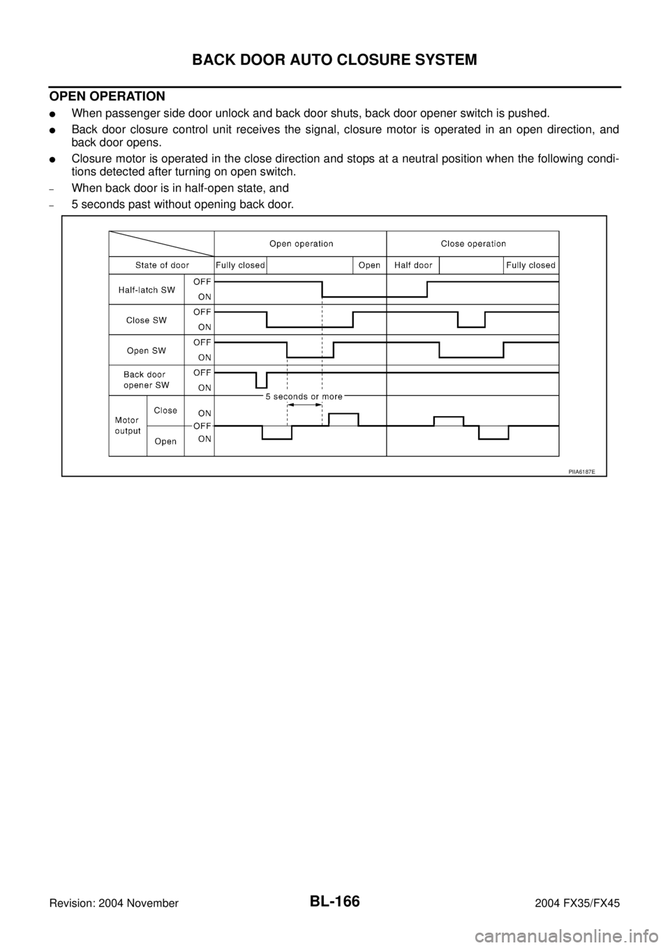
OPEN OPERATION
�When passenger side door unlock and back door shuts, back door opener switch is pushed.
�Back door closure control unit receives the signal, closure motor is operated in an open direction, and
back door opens.
�Closure motor is operated in the close direction and stops at a neutral position when the following condi-
tions detected after turning on open switch.
–When back door is in half-open state, and
–5 seconds past without opening back door.
PIIA6187E
Page 978 of 4449

BACK DOOR AUTO CLOSURE SYSTEM
BL-171
C
D
E
F
G
H
J
K
L
MA
B
BL
Revision: 2004 November 2004 FX35/FX45
Back Door Closure Control Unit Power Supply and Ground Circuit CheckAIS004OK
1. CHECK POWER SUPPLY CIRCUIT
1. Turn ignition switch OFF.
2. Check voltage between back door closure control unit connector
D106 terminal 1 and ground.
OK or NG
OK >> GO TO 2.
NG >> Check the following.
�15A fuse [No.18, located in fuse block (J/B)]
�Harness for open or short between back door closure
control unit and fuse.
2. CHECK GROUND CIRCUIT
1. Disconnect back door closure control unit connector.
2. Check continuity between back door closure control unit con-
nector D106 terminal 4 and ground.
OK or NG
OK >> Power supply and ground circuit are OK.
NG >> Repair or replace harness.
Half-Latch Switch CheckAIS004OL
1. CHECK HALF-LATCH SWITCH SIGNAL
1. Turn ignition switch OFF.
2. Check the signal between back door closure control unit connector and ground with oscilloscope.
OK or NG
OK >> Half-latch switch is OK.
NG >> GO TO 2.1 (R) – Ground : Battery voltage
PIIA6166E
4 (B) – Ground : Continuity should exist.
PIIA6167E
Con-
nectorTerminals (Wire color)
Back door
conditionSignal
(Reference value)
(+) (-)
D106 7 (OR) GroundFully open →
fully closed
PIIA6168E
SIIA1479J
Page 980 of 4449

BACK DOOR AUTO CLOSURE SYSTEM
BL-173
C
D
E
F
G
H
J
K
L
MA
B
BL
Revision: 2004 November 2004 FX35/FX45
Close Switch CheckAIS004OM
1. CHECK CLOSE SWITCH SIGNAL
1. Turn ignition switch OFF.
2. Check the signal between back door closure control unit connector and ground with oscilloscope.
OK or NG
OK >> Close switch is OK.
NG >> GO TO 2.
2. CHECK HARNESS CONTINUITY
1. Disconnect back door closure control unit and back door closure motor connector.
2. Check continuity between back door closure control unit con-
nector D106 terminal 8 and back door closure motor connector
D109 terminal 5.
3. Check continuity between back door closure control unit con-
nector D106 terminal 8 and ground.
OK or NG
OK >> GO TO 3.
NG >> Repair or replace harness.
3. CHECK GROUND CIRCUIT
Check continuity between back door closure motor connector D109
terminal 8 and ground.
OK or NG
OK >> GO TO 4.
NG >> Repair or replace harness.
Con-
nectorTerminals (Wire color)
Back door
conditionSignal
(Reference value)
(+) (-)
D106 8 (L) GroundFully open →
fully closed
PIIA6171E
SIIA1478J
8 (L) – 5 (L) : Continuity should exist.
8 (L) – Ground : Continuity should not exist.
PIIA6174E
8 (B) – Ground : Continuity should exist.
PIIA6170E
Page 981 of 4449

BL-174
BACK DOOR AUTO CLOSURE SYSTEM
Revision: 2004 November 2004 FX35/FX45
4. CHECK BACK DOOR CLOSURE CONTROL UNIT OUTPUT SIGNAL
1. Connect back door closure control unit connector.
2. Check voltage between back door closure control unit connector
D106 terminal 8 and ground.
OK or NG
OK >> Replace back door lock assembly.
NG >> Replace back door closure control unit.
Open Switch CheckAIS004ON
1. CHECK OPEN SWITCH SIGNAL
1. Turn ignition switch OFF.
2. Check the signal between back door closure control unit connector and ground with oscilloscope.
OK or NG
OK >> Open switch is OK.
NG >> GO TO 2.
2. CHECK HARNESS CONTINUITY
1. Disconnect back door closure control unit and back door closure motor connector.
2. Check continuity between back door closure control unit con-
nector D106 terminal 9 and back door closure motor connector
D109 terminal 4.
3. Check continuity between back door closure control unit con-
nector D106 terminal 9 and ground.
OK or NG
OK >> GO TO 3.
NG >> Repair or replace harness.Back door is closed
8 (L) – Ground : Battery voltage
PIIA6173E
Con-
nectorTerminals (Wire color)
Back door
conditionSignal
(Reference value)
(+) (-)
D106 9 (P) GroundFully open →
fully closed
PIIA6175E
SIIA1481J
9 (P) – 4 (P) : Continuity should exist.
9 (P) – Ground : Continuity should not exist.
PIIA6176E
Page 982 of 4449

BACK DOOR AUTO CLOSURE SYSTEM
BL-175
C
D
E
F
G
H
J
K
L
MA
B
BL
Revision: 2004 November 2004 FX35/FX45
3. CHECK GROUND CIRCUIT
Check continuity between back door closure motor connector D109
terminal 8 and ground.
OK or NG
OK >> GO TO 4.
NG >> Repair or replace harness.
4. CHECK BACK DOOR CLOSURE CONTROL UNIT OUTPUT SIGNAL
1. Connect back door closure control unit connector.
2. Check voltage between back door closure control unit connector
D106 terminal 9 and ground.
OK or NG
OK >> Replace back door lock assembly.
NG >> Replace back door closure control unit.
Back Door Opener Switch Check (With Intelligent Key)AIS004U8
1. CHECK BACK DOOR OPENER SWITCH SIGNAL
1. Turn ignition switch OFF.
2. Check voltage between back door closure control unit connector and ground.
OK or NG
OK >> Back door opener switch is OK.
NG >> GO TO 2.8 (B) – Ground : Continuity should exist.
PIIA6170E
Back door is closed
9 (P) – Ground : Battery voltage
PIIA6177E
ConnectorTerminals (Wire color)
ConditionVoltage (V)
(Approx.)
(+) (-)
D106 6 (LG) GroundBack door opener switch
: ON0
Back door opener switch
: OFF5
PIIA6178E
Page 984 of 4449

BACK DOOR AUTO CLOSURE SYSTEM
BL-177
C
D
E
F
G
H
J
K
L
MA
B
BL
Revision: 2004 November 2004 FX35/FX45
6. CHECK BACK DOOR CLOSURE CONTROL UNIT OUTPUT SIGNAL
1. Connect back door closure control unit connector.
2. Check voltage between back door closure control unit connector
D106 terminal 6 and ground.
OK or NG
OK >> Replace Intelligent Key unit.
NG >> Replace back door closure control unit.
Back Door Opener Switch Check (Without Intelligent Key)AIS004U9
1. CHECK BACK DOOR OPENER SWITCH SIGNAL
1. Turn ignition switch OFF.
2. Check voltage between back door closure control unit connector and ground.
OK or NG
OK >> Back door opener switch is OK.
NG >> GO TO 2.
2. CHECK HARNESS CONTINUITY
1. Disconnect back door closure control unit and back door opener switch connector.
2. Check continuity between back door closure control unit con-
nector D106 terminal 6 and back door opener switch connector
D112 terminal 1.
OK or NG
OK >> GO TO 3.
NG >> Repair or replace harness between back door closure
control unit and back door opener switch. 6 (LG) – Ground : Approx. 5V
PIIA6178E
ConnectorTerminals (Wire color)
ConditionVoltage (V)
(Approx.)
(+) (-)
D106 6 (Y) GroundBack door opener switch
: ON0
Back door opener switch
: OFF5
PIIA6178E
6 (Y) – 1 (Y) : Continuity should exist.
PIIA6179E