Page 3037 of 4449
FFD-2
PRECAUTIONS
Revision: 2004 November 2004 FX35/FX45
PRECAUTIONSPFP:00001
PrecautionsADS000N3
CAUTION:
�Before starting diagnosis of the vehicle, understand symptoms well. Perform correct and system-
atic operations.
�Check for the correct installation status prior removal or disassembly. When mating marks are
required, be sure they do not interfere with the function of the parts they are applied to.
�Carry out an overhaul in a clean work place, Using a dust proof room is recommended.
�Before disassembly, using steam or white gasoline, completely remove sand and mud from the
exterior the unit, preventing them from entering into the unit during disassembly or assembly.
�Check appearance of the disassembled parts for damage, deformation, and abnormal wear. If a
malfunction is detected, replace it with a new one.
�Normally replace lock pins, oil seals, and bearings with new ones every times they are removed.
�In principle, tighten bolts or nuts gradually in several steps working diagonally from inside to out-
side. If tightening sequence is specified, observe it.
�Clean and flush the parts sufficiently and blow them dry.
�Be careful not to damage the sliding surfaces and mating surface.
�When applying sealant, remove the old sealant from the mounting surface; then remove any mois-
ture, oil, and foreign materials from the application and mounting surfaces.
�Always use shop paper for cleaning the inside of components.
�Avoid using cotton gloves or a shop cloth to prevent entering of lint.
�During assembly, observe the specified tightening torque, and new differential oil, Vaseline, or
multi-purpose grease, as specified for each vehicle, when necessary.
Page 3041 of 4449
FFD-6
NOISE, VIBRATION AND HARSHNESS (NVH) TROUBLESHOOTING
Revision: 2004 November 2004 FX35/FX45
NOISE, VIBRATION AND HARSHNESS (NVH) TROUBLESHOOTINGPFP:00003
NVH Troubleshooting ChartADS000N6
Use the chart below to help you find the cause of the symptom. If necessary, repair or replace these parts.
×: ApplicableReference page
Refer to FFD-24, "
INSPECTION
" .
Refer to FFD-30, "
TOOTH CONTACT INSPECTION
" .
Refer to FFD-24, "
INSPECTION
" .
Refer to RFD-13, "
Pre-Inspection
"
—
Refer to MA-31, "
Checking Differential Gear Oil
" .
NVH in PR section.
NVH in FAX, RAX, FSU and RSU sections.
NVH in WT section.
NVH in WT section.
NVH in FAX section.
NVH in BR section.
NVH in PS section.
Possible cause and suspected parts
Rough gear tooth
Improper gear contact
Tooth surfaces worn
Incorrect backlash
Companion flange excessive runout
Improper gear oil
Propeller shaft
Axle and suspension
Tire s
Road wheel
Drive shaft
Brakes
Steering
Symptom Differential Noise×××××××××××××
Page 3045 of 4449
FFD-10
FRONT FINAL DRIVE ASSEMBLY
Revision: 2004 November 2004 FX35/FX45
FRONT FINAL DRIVE ASSEMBLYPFP:38500
Removal and Installation (VQ35DE)ADS000N9
REMOVAL
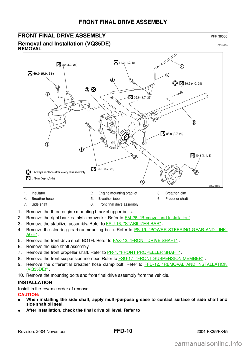
1. Remove the three engine mounting bracket upper bolts.
2. Remove the right bank catalytic converter. Refer to EM-26, "
Removal and Installation" .
3. Remove the stabilizer assembly. Refer to FSU-16, "
STABILIZER BAR" .
4. Remove the steering gearbox mounting bolts. Refer to PS-19, "
POWER STEERING GEAR AND LINK-
AGE" .
5. Remove the front drive shaft BOTH. Refer to FAX-12, "
FRONT DRIVE SHAFT" .
6. Remove the side shaft assembly.
7. Remove the front propeller shaft. Refer to PR-4, "
FRONT PROPELLER SHAFT" .
8. Remove the front suspension member. Refer to FSU-17, "
FRONT SUSPENSION MEMBER" .
9. Remove the differential breather hose clamp bolt. Refer to FFD-12, "
REMOVAL AND INSTALLATION
(VQ35DE)" .
10. Remove the mounting bolts and front final drive assembly from the vehicle.
INSTALLATION
Install in the reverse order of removal.
CAUTION:
�When installing the side shaft, apply multi-purpose grease to contact surface of side shaft and
side shaft oil seal.
�After installation, check the final drive oil level. Refer to
SDIA1586E
1. Insulator 2. Engine mounting bracket 3. Breather joint
4. Breather hose 5. Breather tube 6. Propeller shaft
7. Side shaft 8. Front final drive assembly
Page 3046 of 4449
FRONT FINAL DRIVE ASSEMBLY
FFD-11
C
E
F
G
H
I
J
K
L
MA
B
FFD
Revision: 2004 November 2004 FX35/FX45
Removal and Installation (VK45DE)ADS000OE
REMOVAL
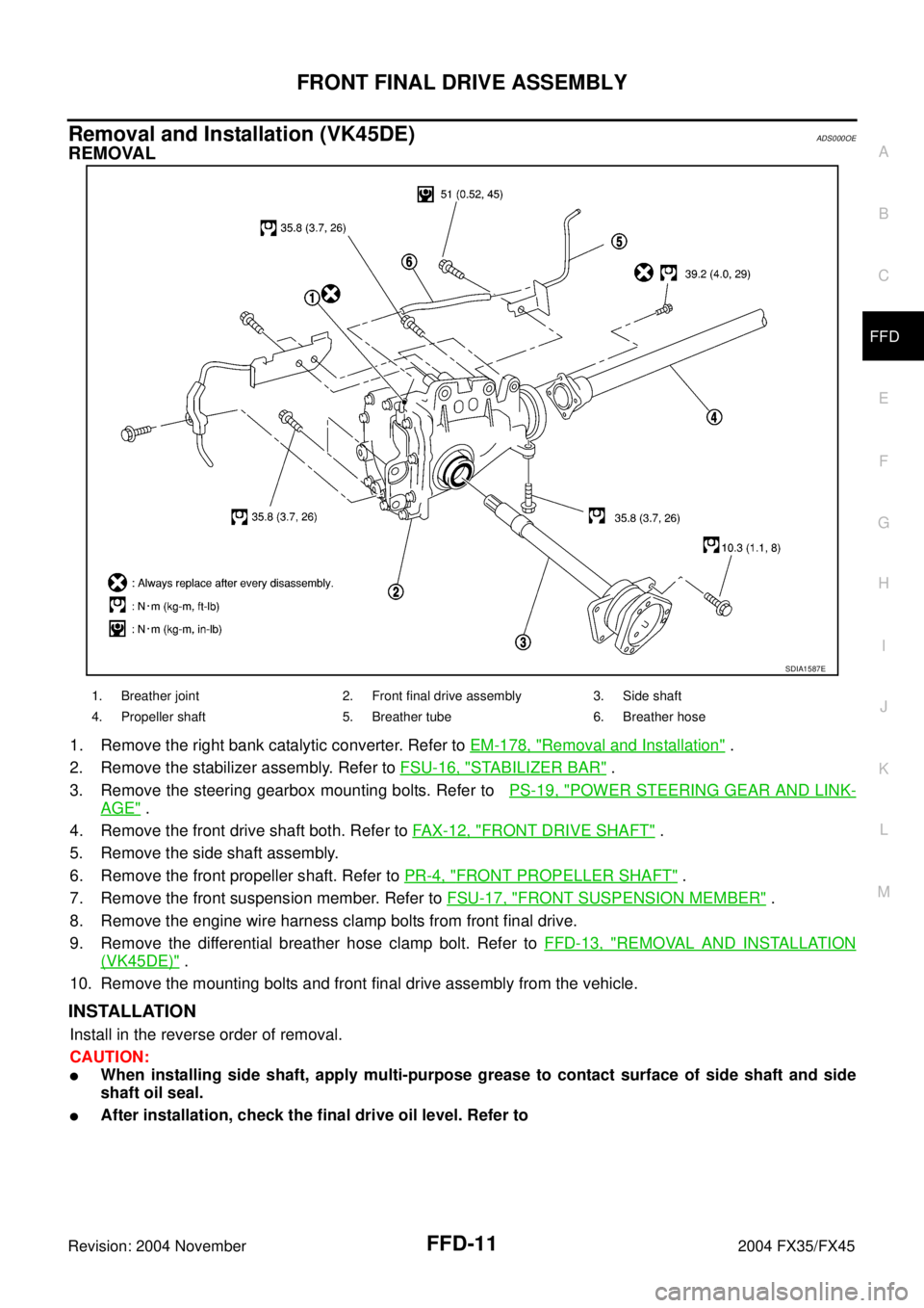
1. Remove the right bank catalytic converter. Refer to EM-178, "Removal and Installation" .
2. Remove the stabilizer assembly. Refer to FSU-16, "
STABILIZER BAR" .
3. Remove the steering gearbox mounting bolts. Refer to PS-19, "
POWER STEERING GEAR AND LINK-
AGE" .
4. Remove the front drive shaft both. Refer to FAX-12, "
FRONT DRIVE SHAFT" .
5. Remove the side shaft assembly.
6. Remove the front propeller shaft. Refer to PR-4, "
FRONT PROPELLER SHAFT" .
7. Remove the front suspension member. Refer to FSU-17, "
FRONT SUSPENSION MEMBER" .
8. Remove the engine wire harness clamp bolts from front final drive.
9. Remove the differential breather hose clamp bolt. Refer to FFD-13, "
REMOVAL AND INSTALLATION
(VK45DE)" .
10. Remove the mounting bolts and front final drive assembly from the vehicle.
INSTALLATION
Install in the reverse order of removal.
CAUTION:
�When installing side shaft, apply multi-purpose grease to contact surface of side shaft and side
shaft oil seal.
�After installation, check the final drive oil level. Refer to
SDIA1587E
1. Breather joint 2. Front final drive assembly 3. Side shaft
4. Propeller shaft 5. Breather tube 6. Breather hose
Page 3056 of 4449
FRONT FINAL DRIVE ASSEMBLY
FFD-21
C
E
F
G
H
I
J
K
L
MA
B
FFD
Revision: 2004 November 2004 FX35/FX45
c. If runout valve still out side of limit after replacing companion flange, check pinion bearing and drive pinion
assembly, and pinion bearing damage.
Tooth Contact
Check tooth contact. Refer to FFD-30, "TOOTH CONTACT INSPECTION" .
DISASSEMBLY AND ASSEMBLY
REMOVAL OF DRIVE GEAR AND DIFFERENTIAL CASE ASSEMBLY
1. Remove the side retainer mounting bolt.
2. Remove the retainer by pulling it and tapping carrier case using a plastic hammer.
3. Remove the differential case assembly from the carrier case.
CAUTION:
Be careful not to damage the carrier cover mating surface.
4. Remove the side bearing outer race using puller.
5. Keep the side bearing outer races together with inner race. Do
not mix them up. Also, keep adjusting washers together with
bearings.
6. Drive out the side oil seals from the carrier case.
SDIA1656E
SDIA0181J
Page 3059 of 4449
FFD-24
FRONT FINAL DRIVE ASSEMBLY
Revision: 2004 November 2004 FX35/FX45
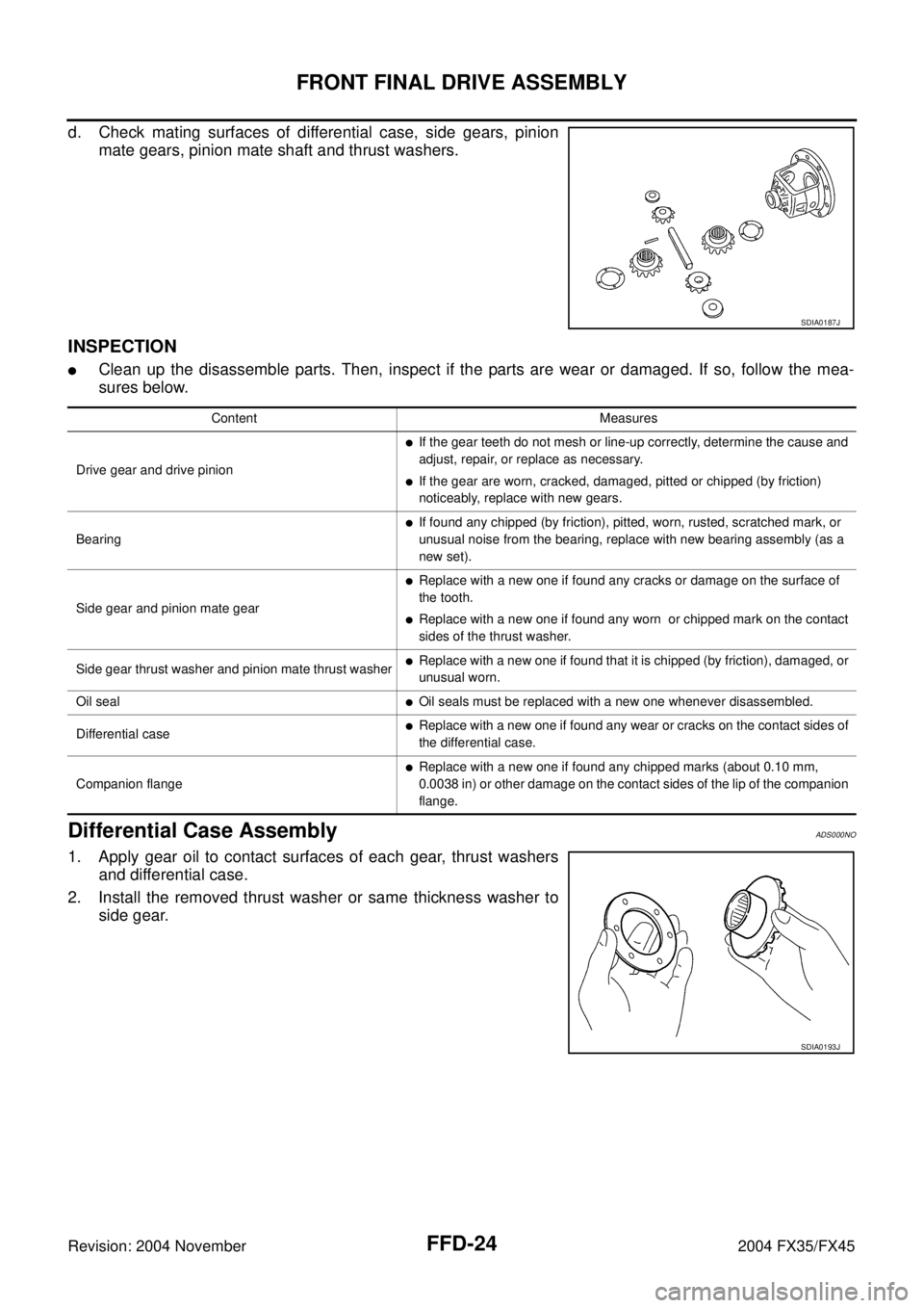
d. Check mating surfaces of differential case, side gears, pinion
mate gears, pinion mate shaft and thrust washers.
INSPECTION
�Clean up the disassemble parts. Then, inspect if the parts are wear or damaged. If so, follow the mea-
sures below.
Differential Case AssemblyADS000NO
1. Apply gear oil to contact surfaces of each gear, thrust washers
and differential case.
2. Install the removed thrust washer or same thickness washer to
side gear.
SDIA0187J
Content Measures
Drive gear and drive pinion
�If the gear teeth do not mesh or line-up correctly, determine the cause and
adjust, repair, or replace as necessary.
�If the gear are worn, cracked, damaged, pitted or chipped (by friction)
noticeably, replace with new gears.
Bearing
�If found any chipped (by friction), pitted, worn, rusted, scratched mark, or
unusual noise from the bearing, replace with new bearing assembly (as a
new set).
Side gear and pinion mate gear
�Replace with a new one if found any cracks or damage on the surface of
the tooth.
�Replace with a new one if found any worn or chipped mark on the contact
sides of the thrust washer.
Side gear thrust washer and pinion mate thrust washer
�Replace with a new one if found that it is chipped (by friction), damaged, or
unusual worn.
Oil seal
�Oil seals must be replaced with a new one whenever disassembled.
Differential case
�Replace with a new one if found any wear or cracks on the contact sides of
the differential case.
Companion flange
�Replace with a new one if found any chipped marks (about 0.10 mm,
0.0038 in) or other damage on the contact sides of the lip of the companion
flange.
SDIA0193J
Page 3065 of 4449
FFD-30
FRONT FINAL DRIVE ASSEMBLY
Revision: 2004 November 2004 FX35/FX45
TOOTH CONTACT INSPECTION
Checking gear tooth contact pattern is necessary to verify correct relationship between drive gear and drive
pinion.
Hypoid gears which are not positioned in proper arrangement may be noisy and/or have a short life. Check
gear tooth contact pattern to obtain the best contact for low noise and long life.
1. Thoroughly clean drive gear and drive pinion teeth.
2. Lightly apply a mixture of powdered ferric oxide and oil or the
equivalent. Apply it to 3 or 4 teeth on the drive side of drive
gear.
3. Hold companion flange steady by hand and rotate the drive gear
in both directions.
4. Check the tooth contact on both sides (drive side and coast
side).
NOTE:
Refer to FFD-31, "
TOOTH CONTACT PATTERN AND HEIGHT
ADJUSTING WASHER SELECTION" for detail of tooth contact
pattern.
SDIA0054J
SDIA1711E
Page 3068 of 4449
FRONT FINAL DRIVE ASSEMBLY
FFD-33
C
E
F
G
H
I
J
K
L
MA
B
FFD
Revision: 2004 November 2004 FX35/FX45
TOTAL PRELOAD INSPECTION
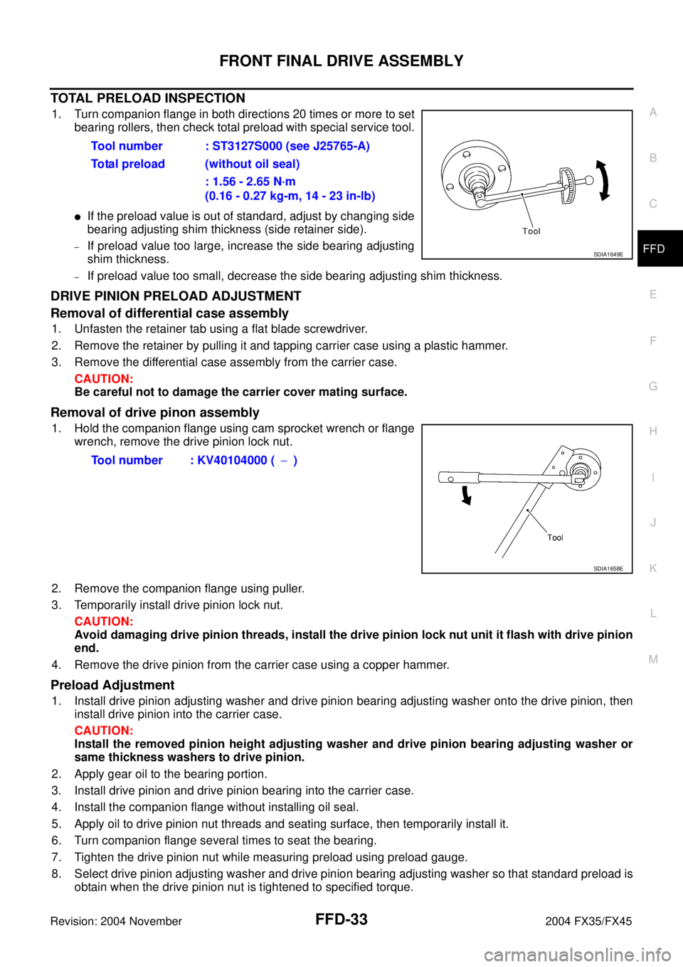
1. Turn companion flange in both directions 20 times or more to set
bearing rollers, then check total preload with special service tool.
�If the preload value is out of standard, adjust by changing side
bearing adjusting shim thickness (side retainer side).
–If preload value too large, increase the side bearing adjusting
shim thickness.
–If preload value too small, decrease the side bearing adjusting shim thickness.
DRIVE PINION PRELOAD ADJUSTMENT
Removal of differential case assembly
1. Unfasten the retainer tab using a flat blade screwdriver.
2. Remove the retainer by pulling it and tapping carrier case using a plastic hammer.
3. Remove the differential case assembly from the carrier case.
CAUTION:
Be careful not to damage the carrier cover mating surface.
Removal of drive pinon assembly
1. Hold the companion flange using cam sprocket wrench or flange
wrench, remove the drive pinion lock nut.
2. Remove the companion flange using puller.
3. Temporarily install drive pinion lock nut.
CAUTION:
Avoid damaging drive pinion threads, install the drive pinion lock nut unit it flash with drive pinion
end.
4. Remove the drive pinion from the carrier case using a copper hammer.
Preload Adjustment
1. Install drive pinion adjusting washer and drive pinion bearing adjusting washer onto the drive pinion, then
install drive pinion into the carrier case.
CAUTION:
Install the removed pinion height adjusting washer and drive pinion bearing adjusting washer or
same thickness washers to drive pinion.
2. Apply gear oil to the bearing portion.
3. Install drive pinion and drive pinion bearing into the carrier case.
4. Install the companion flange without installing oil seal.
5. Apply oil to drive pinion nut threads and seating surface, then temporarily install it.
6. Turn companion flange several times to seat the bearing.
7. Tighten the drive pinion nut while measuring preload using preload gauge.
8. Select drive pinion adjusting washer and drive pinion bearing adjusting washer so that standard preload is
obtain when the drive pinion nut is tightened to specified torque.Tool number : ST3127S000 (see J25765-A)
Total preload (without oil seal)
: 1.56 - 2.65 N·m
(0.16 - 0.27 kg-m, 14 - 23 in-lb)
SDIA1649E
Tool number : KV40104000 (−)
SDIA1658E