Page 4281 of 4449

SRS-40
FRONT PASSENGER AIR BAG MODULE
Revision: 2004 November 2004 FX35/FX45
FRONT PASSENGER AIR BAG MODULEPFP:K8515
Removal and InstallationAHS000HY
REMOVAL
CAUTION:
�Before servicing SRS, turn ignition switch OFF, disconnect both battery cables and wait at least 3
minutes.
�Always work from the side of or under front passenger air bag module.
1. Remove instrument passenger lower panel and glove box. Refer to IP-10, "
INSTRUMENT PANEL
ASSEMBLY" .
2. Remove display control unit, if navigation system is equipped.
3. Remove tire pressure warning control unit, if tire pressure warning control system is equipped.
4. Disconnect front passenger air bag module connector.
5. Remove the front passenger air bag module fixing nuts and bolt,
then remove front passenger air bag module.
CAUTION:
�Always place front passenger air bag module with caution
label side facing upward.
�Do not insert any foreign objects (screwdriver, etc.) into
front passenger air bag module.
�Do not disassemble front passenger air bag module.
�Do not use old bolts after removal; replace with new bolts.
�Replace front passenger air bag module if it has been
dropped or sustained an impact.
�Do not expose the front passenger air bag module to tem-
peratures exceeding 90°C (194°F).
�Do not allow oil, grease or water to come in contact with the
front passenger air bag module.
�After front passenger air bag module inflates, the instru-
ment panel assembly should be replaced.
INSTALLATION
Install in the reverse order of removal.
CAUTION:
�Always work from the side of or under front passenger air bag module.
�After the work is completed, perform self-diagnosis to make sure no malfunction is detected.
Refer to SRS-17, "
SRS Operation Check" .
PHIA0322E
PHIA0325E
SBF814E
Page 4283 of 4449
SRS-42
FRONT SIDE AIR BAG MODULE
Revision: 2004 November 2004 FX35/FX45
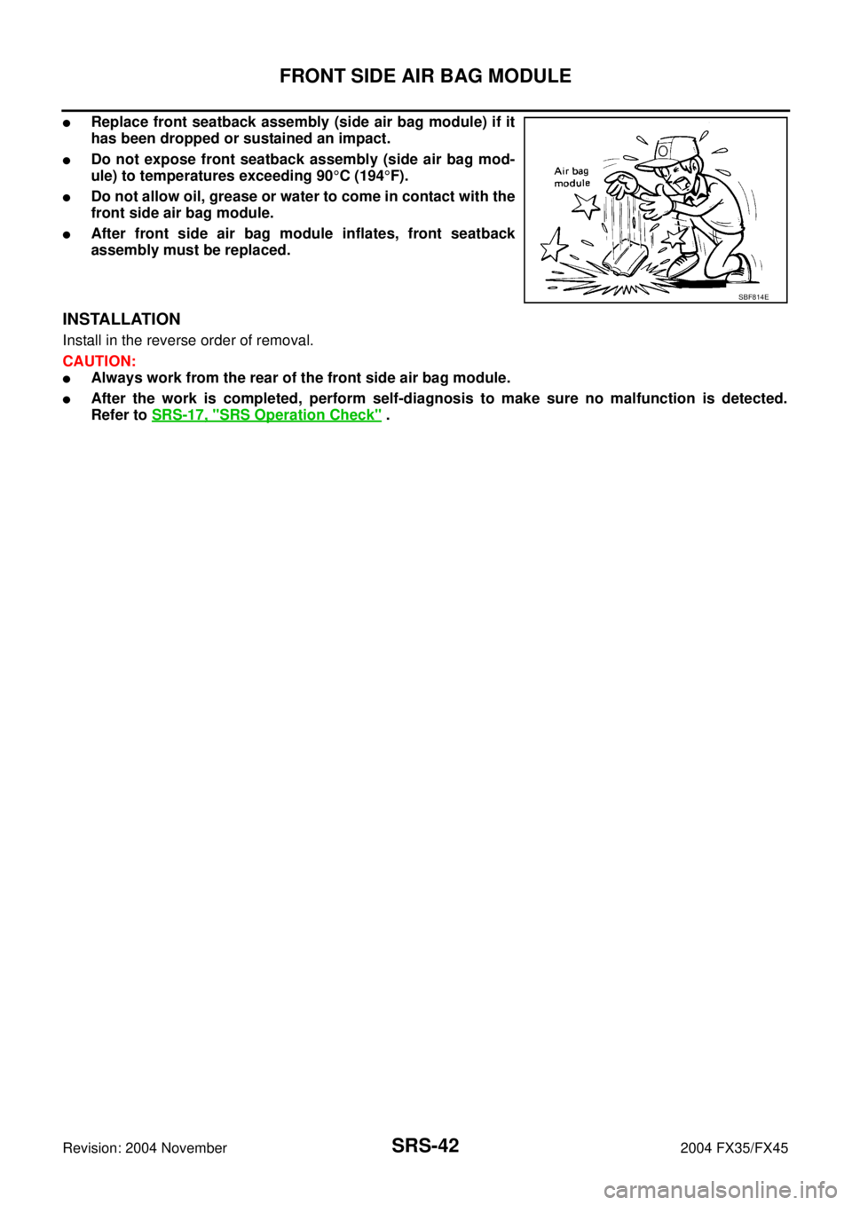
�Replace front seatback assembly (side air bag module) if it
has been dropped or sustained an impact.
�Do not expose front seatback assembly (side air bag mod-
ule) to temperatures exceeding 90°C (194°F).
�Do not allow oil, grease or water to come in contact with the
front side air bag module.
�After front side air bag module inflates, front seatback
assembly must be replaced.
INSTALLATION
Install in the reverse order of removal.
CAUTION:
�Always work from the rear of the front side air bag module.
�After the work is completed, perform self-diagnosis to make sure no malfunction is detected.
Refer to SRS-17, "
SRS Operation Check" .
SBF814E
Page 4340 of 4449
FRONT OIL SEAL
TF-39
C
E
F
G
H
I
J
K
L
MA
B
TF
Revision: 2004 November 2004 FX35/FX45
FRONT OIL SEALPFP:38189
Removal and InstallationADS000RP
REMOVAL
1. Remove the drain plug to drain the transfer fluid. Refer to TF-8, "Replacement" .
2. Remove the front propeller shaft. Refer to PR-4, "
FRONT PROPELLER SHAFT" .
3. Remove front oil seal using a flat-bladed screwdriver.
CAUTION:
Be careful not to damage the center case.
INSTALLATION
1. Apply multi-purpose grease to oil seal lips. Install the front oil
seal with a drift until the end face of front case.
CAUTION:
�Do not reuse front oil seal.
�When installing, do not incline the oil seal.
2. Install front propeller shaft. Refer to PR-4, "
FRONT PROPEL-
LER SHAFT" .
3. Install transfer fluid, check fluid level and for fluid leakage. Refer
to TF-8, "
Inspection" .
SDIA1782E
Tool number : ST27862000 ( — )
SDIA1783E
Page 4342 of 4449
REAR OIL SEAL
TF-41
C
E
F
G
H
I
J
K
L
MA
B
TF
Revision: 2004 November 2004 FX35/FX45
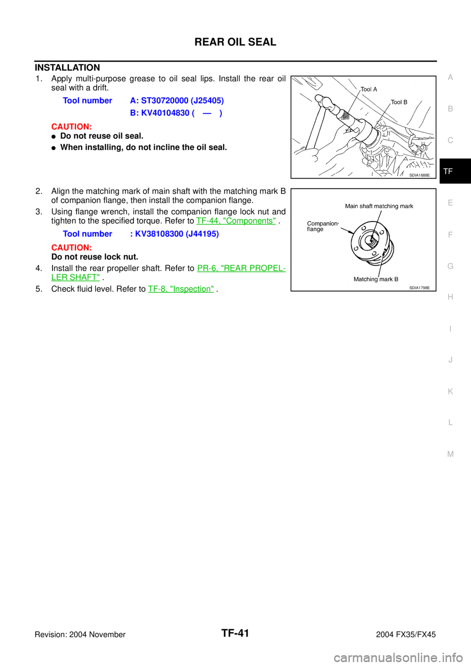
INSTALLATION
1. Apply multi-purpose grease to oil seal lips. Install the rear oil
seal with a drift.
CAUTION:
�Do not reuse oil seal.
�When installing, do not incline the oil seal.
2. Align the matching mark of main shaft with the matching mark B
of companion flange, then install the companion flange.
3. Using flange wrench, install the companion flange lock nut and
tighten to the specified torque. Refer to TF-44, "
Components" .
CAUTION:
Do not reuse lock nut.
4. Install the rear propeller shaft. Refer to PR-6, "
REAR PROPEL-
LER SHAFT" .
5. Check fluid level. Refer to TF-8, "
Inspection" . Tool number A: ST30720000 (J25405)
B: KV40104830 ( — )
SDIA1688E
Tool number : KV38108300 (J44195)
SDIA1798E
Page 4350 of 4449

TRANSFER ASSEMBLY
TF-49
C
E
F
G
H
I
J
K
L
MA
B
TF
Revision: 2004 November 2004 FX35/FX45
Main Shaft and Electric Controlled Coupling
1. Remove the snap ring from main shaft.
2. Remove the spacer, electric controlled coupling, sprocket and
needle bearing from main shaft.
INSPECTION
Gears
�Check the gear faces and shaft for wear, cracks, damage, and seizure.
Bearings
�Check for seizure, peeling, wear, corrosion, sticking/abnormal noise/roughness in hand turning, and other
damage.
CAUTION:
When replacing the bearing, always replace the inner race and outer race as a pair.
Front Case and Rear Case
�Replace with a new one if found any wear or cracks on the contact sides of the case.
Washers
�Check for seizure, damage, and unusual wear.
Oil Seals
�Discard old oil seals, replace with new ones.
�If wear, deterioration of adherence (sealing force of lips), or damage is detected on the lips, replace them.
Snap Ring
�Discard old snap rings, replace with new ones.
Lock Nut
�Discard old lock nut, replace with new ones.
ASSEMBLY
Rear Case
1. Install the baffle plate into rear case.
2. Install the main shaft rear bearing into rear case.
SDIA1602E
SDIA1701E