Page 3943 of 4449
PS-10
STEERING WHEEL
Revision: 2004 November 2004 FX35/FX45
STEERING WHEELPFP:48430
On-Vehicle Inspection and ServiceAGS000GW
CHECKING CONDITION OF INSTALLATION
�Check installation condition of steering gear assembly, front suspension, axle and steering column.
�Check if movement exists when steering wheel is moved up and down, to the left and right and to the axial
direction.
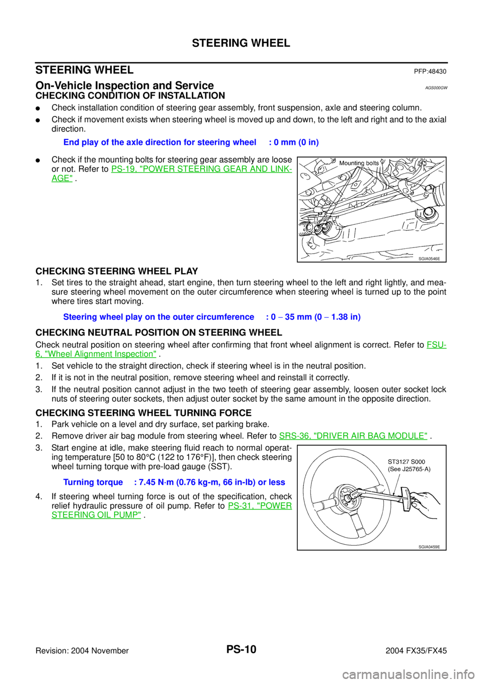
�Check if the mounting bolts for steering gear assembly are loose
or not. Refer to PS-19, "
POWER STEERING GEAR AND LINK-
AGE" .
CHECKING STEERING WHEEL PLAY
1. Set tires to the straight ahead, start engine, then turn steering wheel to the left and right lightly, and mea-
sure steering wheel movement on the outer circumference when steering wheel is turned up to the point
where tires start moving.
CHECKING NEUTRAL POSITION ON STEERING WHEEL
Check neutral position on steering wheel after confirming that front wheel alignment is correct. Refer to FSU-
6, "Wheel Alignment Inspection" .
1. Set vehicle to the straight direction, check if steering wheel is in the neutral position.
2. If it is not in the neutral position, remove steering wheel and reinstall it correctly.
3. If the neutral position cannot adjust in the two teeth of steering gear assembly, loosen outer socket lock
nuts of steering outer sockets, then adjust outer socket by the same amount in the opposite direction.
CHECKING STEERING WHEEL TURNING FORCE
1. Park vehicle on a level and dry surface, set parking brake.
2. Remove driver air bag module from steering wheel. Refer to SRS-36, "
DRIVER AIR BAG MODULE" .
3. Start engine at idle, make steering fluid reach to normal operat-
ing temperature [50 to 80°C (122 to 176°F)], then check steering
wheel turning torque with pre-load gauge (SST).
4. If steering wheel turning force is out of the specification, check
relief hydraulic pressure of oil pump. Refer to PS-31, "
POWER
STEERING OIL PUMP" . End play of the axle direction for steering wheel : 0 mm (0 in)
SGIA0546E
Steering wheel play on the outer circumference : 0 − 35 mm (0 − 1.38 in)
Turning torque : 7.45 N·m (0.76 kg-m, 66 in-lb) or less
SGIA0459E
Page 3953 of 4449
PS-20
POWER STEERING GEAR AND LINKAGE
Revision: 2004 November 2004 FX35/FX45
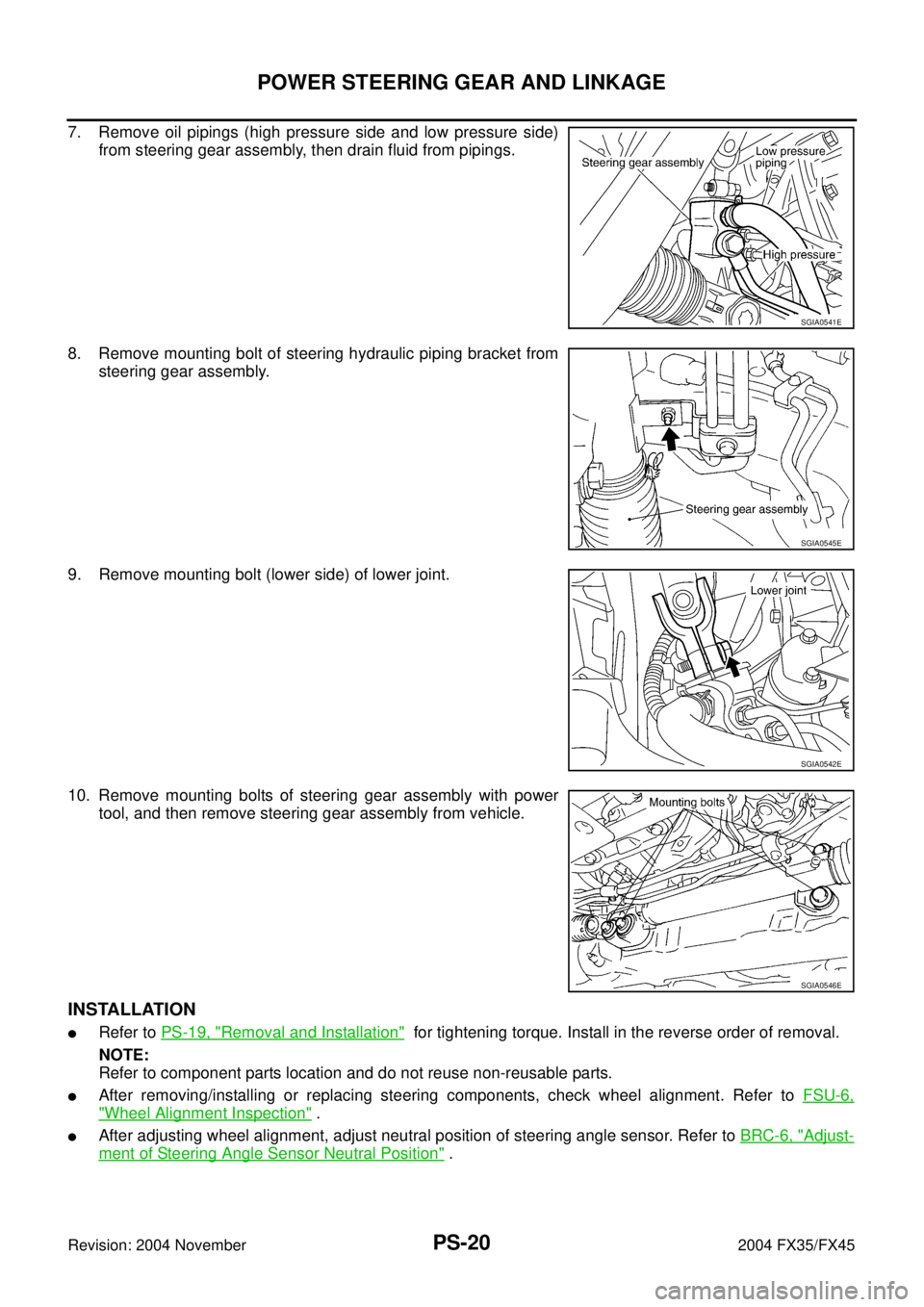
7. Remove oil pipings (high pressure side and low pressure side)
from steering gear assembly, then drain fluid from pipings.
8. Remove mounting bolt of steering hydraulic piping bracket from
steering gear assembly.
9. Remove mounting bolt (lower side) of lower joint.
10. Remove mounting bolts of steering gear assembly with power
tool, and then remove steering gear assembly from vehicle.
INSTALLATION
�Refer to PS-19, "Removal and Installation" for tightening torque. Install in the reverse order of removal.
NOTE:
Refer to component parts location and do not reuse non-reusable parts.
�After removing/installing or replacing steering components, check wheel alignment. Refer to FSU-6,
"Wheel Alignment Inspection" .
�After adjusting wheel alignment, adjust neutral position of steering angle sensor. Refer to BRC-6, "Adjust-
ment of Steering Angle Sensor Neutral Position" .
SGIA0541E
SGIA0545E
SGIA0542E
SGIA0546E
Page 3964 of 4449
POWER STEERING OIL PUMP
PS-31
C
D
E
F
H
I
J
K
L
MA
B
PS
Revision: 2004 November 2004 FX35/FX45
POWER STEERING OIL PUMPPFP:49110
On-Vehicle Inspection and ServiceAGS000H2
CHECKING RELIEF OIL PRESSURE (VQ35DE MODELS)
CAUTION:
Before starting work, confirm belt tension is proper.
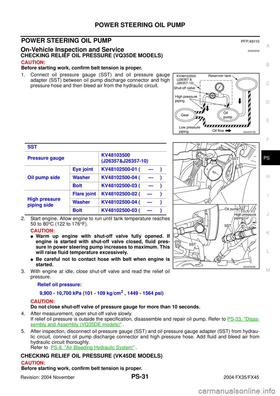
1. Connect oil pressure gauge (SST) and oil pressure gauge
adapter (SST) between oil pump discharge connector and high
pressure hose and then bleed air from the hydraulic circuit.
2. Start engine. Allow engine to run until tank temperature reaches
50 to 80°C (122 to 176°F).
CAUTION:
�Warm up engine with shut-off valve fully opened. If
engine is started with shut-off valve closed, fluid pres-
sure in power steering pump increases to maximum. This
will raise fluid temperature excessively.
�Be careful not to contact hose with belt when engine is
started.
3. With engine at idle, close shut-off valve and read the relief oil
pressure.
CAUTION:
Do not close shut-off valve of pressure gauge for more than 10 seconds.
4. After measurement, open shut-off valve slowly.
If relief oil pressure is outside the specification, disassemble and repair oil pump. Refer to PS-33, "
Disas-
sembly and Assembly (VQ35DE models)" .
5. After inspection, disconnect oil pressure gauge (SST) and oil pressure gauge adapter (SST) from hydrau-
lic circuit, connect oil pump discharge connector and high pressure hose. Add fluid and bleed air from
hydraulic circuit thoroughly.
Refer to PS-8, "
Air Bleeding Hydraulic System" .
CHECKING RELIEF OIL PRESSURE (VK45DE MODELS)
CAUTION:
Before starting work, confirm belt tension is proper.
SGIA0570E
SST
Pressure gaugeKV48103500
(J26357&J26357-10)
Oil pump sideEye joint KV48102500-01 ( — )
Washer KV48102500-04 ( — )
Bolt KV48102500-03 ( — )
High pressure
piping sideFlare joint KV48102500-02 ( — )
Washer KV48102500-04 ( — )
Bolt KV48102500-03 ( — )
Relief oil pressure:
9,900 - 10,700 kPa (101 - 109 kg/cm
2 , 1449 - 1564 psi)
SGIA0522E
Page 3965 of 4449
PS-32
POWER STEERING OIL PUMP
Revision: 2004 November 2004 FX35/FX45
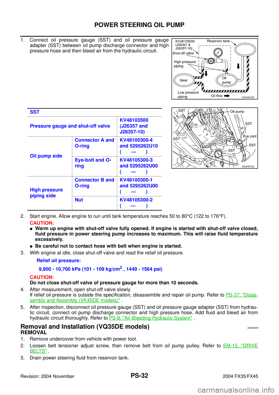
1. Connect oil pressure gauge (SST) and oil pressure gauge
adapter (SST) between oil pump discharge connector and high
pressure hose and then bleed air from the hydraulic circuit.
2. Start engine. Allow engine to run until tank temperature reaches 50 to 80°C (122 to 176°F).
CAUTION:
�Warm up engine with shut-off valve fully opened. If engine is started with shut-off valve closed,
fluid pressure in power steering pump increases to maximum. This will raise fluid temperature
excessively.
�Be careful not to contact hose with belt when engine is started.
3. With engine at idle, close shut-off valve and read the relief oil pressure.
CAUTION:
Do not close shut-off valve of pressure gauge for more than 10 seconds.
4. After measurement, open shut-off valve slowly.
If relief oil pressure is outside the specification, disassemble and repair oil pump. Refer to PS-37, "
Disas-
sembly and Assembly (VK45DE models)" .
5. After inspection, disconnect oil pressure gauge (SST) and oil pressure gauge adapter (SST) from hydrau-
lic circuit, connect oil pump discharge connector and high pressure hose. Add fluid and bleed air from
hydraulic circuit thoroughly. Refer to PS-8, "
Air Bleeding Hydraulic System" .
Removal and Installation (VQ35DE models)AGS000HI
REMOVAL
1. Remove undercover from vehicle with power tool.
2. Loosen belt tensioner adjust screw, then remove belt from oil pump pulley. Refer to EM-15, "
DRIVE
BELTS" .
3. Drain power steering fluid from reservoir tank.
SGIA0570E
SST
Pressure gauge and shut-off valveKV48103500
(J26357 and
J26357-10)
Oil pump sideConnector A and
O-ringKV48105300-4
and 5295262U10
(—)
Eye-bolt and O-
ringKV48105300-3
and 5295262U00
(—)
High pressure
piping sideConnector B and
O-ringKV48105300-1
and 5295262U00
(—)
Nut KV48105300-2
( — )
SGIA0572E
Relief oil pressure:
9,900 - 10,700 kPa (101 - 109 kg/cm
2 , 1449 - 1564 psi)
Page 3966 of 4449
POWER STEERING OIL PUMP
PS-33
C
D
E
F
H
I
J
K
L
MA
B
PS
Revision: 2004 November 2004 FX35/FX45
4. Remove piping of high pressure and low pressure (drain fluid from their pipings). Refer to PS-41,
"HYDRAULIC LINE" .
5. Remove mounting bolts, then remove power steering pump.
INSTALLATION
Refer to PS-41, "HYDRAULIC LINE" for tightening torque. Install in the reverse order removal.
�After installation, adjust belt tension. Refer to EM-15, "DRIVE BELTS" .
�After installation, bleed air. Refer to PS-8, "Air Bleeding Hydraulic System" .
Removal and Installation (VK45DE models)AGS000HJ
REMOVAL
1. Remove undercover from vehicle with power tool.
2. Remove power steering oil pump belt from auto tensioner. Refer to EM-169, "
DRIVE BELTS" .
3. Drain power steering fluid from reservoir tank.
4. Remove piping of high pressure and low pressure from power steering oil pump (drain fluid from their pip-
ings). Refer to PS-41, "
HYDRAULIC LINE" .
5. Remove mounting bolts, then remove power steering pump.
INSTALLATION
Refer to PS-41, "HYDRAULIC LINE" for tightening torque. Install in the reverse order removal.
After installation, bleed air. Refer to PS-8, "
Air Bleeding Hydraulic System" .
NOTE:
Adjustment of belt tension is no necessary because engine of this model equips auto tensioner.
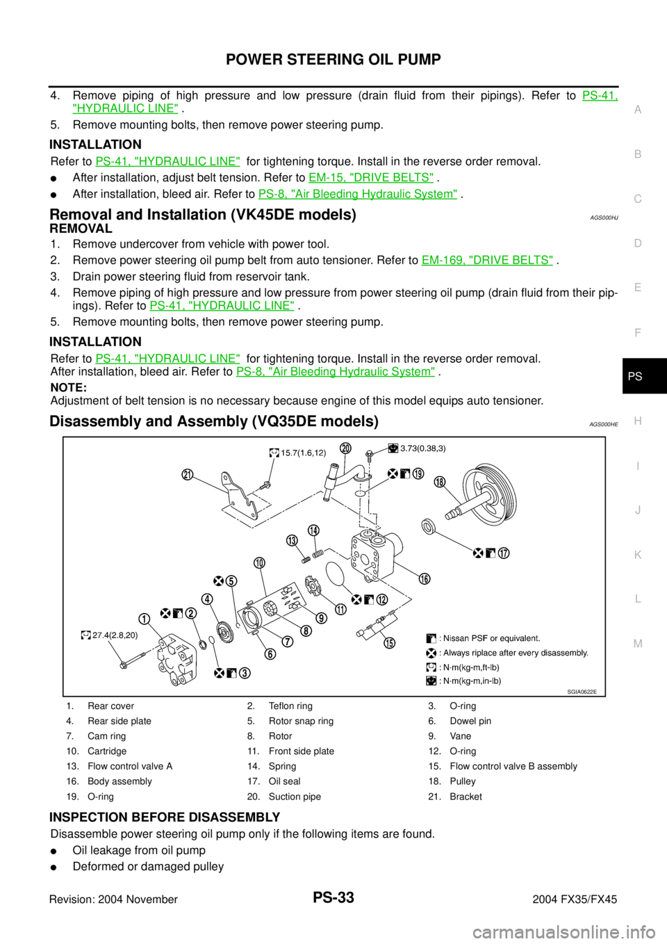
Disassembly and Assembly (VQ35DE models)AGS000HE
INSPECTION BEFORE DISASSEMBLY
Disassemble power steering oil pump only if the following items are found.
�Oil leakage from oil pump
�Deformed or damaged pulley
1. Rear cover 2. Teflon ring 3. O-ring
4. Rear side plate 5. Rotor snap ring 6. Dowel pin
7. Cam ring 8. Rotor 9. Vane
10. Cartridge 11. Front side plate 12. O-ring
13. Flow control valve A 14. Spring 15. Flow control valve B assembly
16. Body assembly 17. Oil seal 18. Pulley
19. O-ring 20. Suction pipe 21. Bracket
SGIA0622E
Page 3974 of 4449
HYDRAULIC LINE
PS-41
C
D
E
F
H
I
J
K
L
MA
B
PS
Revision: 2004 November 2004 FX35/FX45
HYDRAULIC LINEPFP:49721
ComponentsAGS000H5
VQ35DE 2WD MODEL
SGIA0559E
1. Reservoir tank 2. Reservoir tank bracket 3. Suction hose
4. High pressure hose 5. Oil pump 6. Steering gear assembly
Page 3975 of 4449
PS-42
HYDRAULIC LINE
Revision: 2004 November 2004 FX35/FX45
VQ35DE AWD MODEL
7. Oil cooler 8. Eye bolt 9. Copper washer
10. Oil pressure sensor
SGIA0560E
1. Reservoir tank 2. Reservoir tank bracket 3. Suction hose
4. High pressure hose 5. Oil pump 6. Steering gear assembly
7. Oil cooler 8. Eye bolt 9. Copper washer
10. Oil pressure sensor
Page 3977 of 4449
PS-44
HYDRAULIC LINE
Revision: 2004 November 2004 FX35/FX45
ComponentAGS000HF
VK45DE AWD MODEL
SGIA0727E
1. Reservoir tank 2. Suction hose 3. High pressure hose
4. Oil cooler 5. Steering gear assembly 6. Reservoir tank bracket
7. Eye bolt