Page 3980 of 4449
SERVICE DATA AND SPECIFICATIONS (SDS)
PS-47
C
D
E
F
H
I
J
K
L
MA
B
PS
Revision: 2004 November 2004 FX35/FX45
Steering GearAGS000HB
Oil PumpAGS000HC
Steering FluidAGS000HD
Tie-rod length “L” 135.2 mm (5.32 in)
SGIA0167E
Steering gear modelPR26AM
Rack neutral position, dimension “L” (rack stroke) 67.0 mm (2.638 in)
Rack sliding forceAt the neutral point:
Range within ± 11.5 mm
(±0.453 in) from the neutral
position
(in power ON)Area average value 147 − 211 N (14.99 − 21.52 kg, 33.1 − 47.52 lb)
Allowable variation 98 N (10 kg, 22 lb) or less
Whole area (in power OFF)Peak value 294 N (30.0 kg, 66 lb) or less
Allowable variation 147 N (16 kg, 35 lb) or less
SGIA0629J
Oil pump relief hydraulic pressure
9,900 − 10,700 kPa (101 − 109 kg/cm2 , 1449 − 1564, psi)
Fluid capacity
Approx. 1.0 (1-1/8 US qt, 7/8 Imp qt)
Page 4064 of 4449

REAR SUSPENSION ASSEMBLY
RSU-5
C
D
F
G
H
I
J
K
L
MA
B
RSU
Revision: 2004 November 2004 FX35/FX45
REAR SUSPENSION ASSEMBLYPFP:55020
On-Vehicle Inspection and ServiceAES000MJ
Make sure the mounting conditions (looseness, back lash) of each component and component status (wear,
damage) are normal.
INSPECTION OF SUSPENSION ARM BALL JOINT END PLAY
Measure axial end play by installing and moving up/down between suspension arm and axle with an iron pry
bar or something similar.
CAUTION:
Be careful not to damage ball joint boot.
SHOCK ABSORBER INSPECTION
Check shock absorber for oil leakage, damage and replace if necessary.
Wheel Alignment InspectionAES000MK
DESCRIPTION
Measure wheel alignment under unladen conditions. “Unladen conditions” mean that fuel, engine coolant, and
lubricant are full. Spare tire, jack, hand tools and mats are in designated positions.
PRELIMINARY CHECK
1. Check tires for improper air pressure and wear.
2. Check road wheels for runout.
3. Check wheel bearing axial end play.
4. Check suspension arm ball joint axial end play.
5. Check shock absorber operation.
6. Check each mounting part of axle and suspension for looseness and deformation.
7. Check each link, arm and member for cracks, deformation, and other damage.
8. Check vehicle posture.
CAMBER INSPECTION
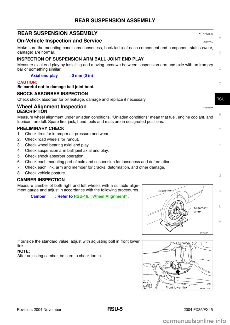
Measure camber of both right and left wheels with a suitable align-
ment gauge and adjust in accordance with the following procedures.
If outside the standard value, adjust with adjusting bolt in front lower
link.
NOTE:
After adjusting camber, be sure to check toe-in.Axial end play : 0 mm (0 in)
Camber : Refer to RSU-18, "
Wheel Alignment" .
SRA096A
SEIA0318E
Page 4125 of 4449
SC-36
CHARGING SYSTEM
Revision: 2004 November 2004 FX35/FX45
7. Remove oil pressure switch harness clip from alternator stay.
(2WD)
8. Disconnect oil pressure switch connector. (2WD)
9. Remove alternator stay mounting bolts and alternator stay, using
power tools.
10. Remove alternator mounting bolt, using power tools.
11. Remove alternator assembly to the direction of under side the vehicle.
Installation
Note the following, and install in the reverse order of removal.
�Install alternator, and check tension of belt. Refer to EM-15, "Checking Drive Belts" in “ENGINE
MECHANICAL (EM)” section.
CAUTION:
Be sure to tighten B terminal nut carefully.
PKIA1923E
Page 4128 of 4449

SERVICE DATA AND SPECIFICATIONS (SDS)
SC-39
C
D
E
F
G
H
I
J
L
MA
B
SC
Revision: 2004 November 2004 FX35/FX45
SERVICE DATA AND SPECIFICATIONS (SDS)PFP:00030
BatteryAKS0079N
StarterAKS0079O
AlternatorAKS0079P
Type80D23L
Capacity V - AH 12 - 52
Cold cranking current (For reference value)
A582
Applied model VK45DE VQ35DE (2WD) VQ35DE (AWD)
Ty p eM2T85075 S114 - 880 S114 - 881
MITSUBISHI
makeHITACHI make
Reduction gear type
System voltage V 12
No-loadTerminal voltage V 11
Current A Less than 145 Less than 90
Revolution rpm More than 3,300 More than 2,880
Minimum diameter of commutator mm (in) 31.4 (1.236) 28.0 (1.102)
Minimum length of brush mm (in) 11.0 (0.433) 10.5 (0.413)
Brush spring tension N (kg, lb)26.7 - 36.1
(2.72 - 3.68,
6.80 - 8.12)16.2 (1.65, 3.6)
Clearance between bearing metal and armature shaft mm (in) Less than 0.2 (0.008)
Clearance between pinion front edge and pinion stopper mm (in)0.5 - 2.0
(0.020 - 0.079)0.3 - 2.5 (0.012 - 0.098)
Applied model VK45DE VQ35DE
Ty p eLR1110 - 716 A3TG0191
HITACHI make MITSUBISHI make
Nominal rating V - A 12 - 110
Ground polarityNegative
Minimum revolution under no-load (When 13.5V is applied)
rpmLess than 1,100 Less than 1,000
Hot output current (When 13.5V is applied) A/
rpmMore than 70/1,800
More than 91/2,500
More than 110/5,000More than 37/1,300
More than 92/2,500
More than 103/5,000
Regulated output voltage V 14.1 - 14.7
Minimum length of brush mm (in) More than 6.00 (0.236) More than 5.00 (0.197)
Brush spring pressure N (g, oz)1.00 - 3.43
(102 - 350, 3.60 - 12.34)4.9 - 6.1
(499 - 622, 17.62 - 21.94)
Slip ring minimum outer diameter mm (in) More than 26.0 (1.024) More than 22.1 (0.870)
Rotor (Field coil) resistance Ω2.31 1.7 - 2.1
Page 4281 of 4449

SRS-40
FRONT PASSENGER AIR BAG MODULE
Revision: 2004 November 2004 FX35/FX45
FRONT PASSENGER AIR BAG MODULEPFP:K8515
Removal and InstallationAHS000HY
REMOVAL
CAUTION:
�Before servicing SRS, turn ignition switch OFF, disconnect both battery cables and wait at least 3
minutes.
�Always work from the side of or under front passenger air bag module.
1. Remove instrument passenger lower panel and glove box. Refer to IP-10, "
INSTRUMENT PANEL
ASSEMBLY" .
2. Remove display control unit, if navigation system is equipped.
3. Remove tire pressure warning control unit, if tire pressure warning control system is equipped.
4. Disconnect front passenger air bag module connector.
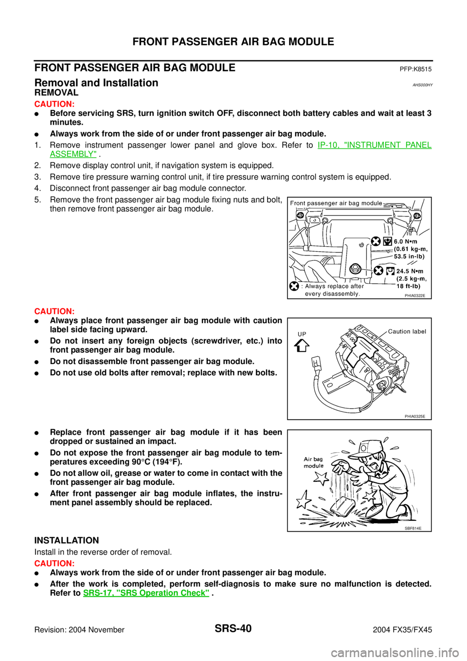
5. Remove the front passenger air bag module fixing nuts and bolt,
then remove front passenger air bag module.
CAUTION:
�Always place front passenger air bag module with caution
label side facing upward.
�Do not insert any foreign objects (screwdriver, etc.) into
front passenger air bag module.
�Do not disassemble front passenger air bag module.
�Do not use old bolts after removal; replace with new bolts.
�Replace front passenger air bag module if it has been
dropped or sustained an impact.
�Do not expose the front passenger air bag module to tem-
peratures exceeding 90°C (194°F).
�Do not allow oil, grease or water to come in contact with the
front passenger air bag module.
�After front passenger air bag module inflates, the instru-
ment panel assembly should be replaced.
INSTALLATION
Install in the reverse order of removal.
CAUTION:
�Always work from the side of or under front passenger air bag module.
�After the work is completed, perform self-diagnosis to make sure no malfunction is detected.
Refer to SRS-17, "
SRS Operation Check" .
PHIA0322E
PHIA0325E
SBF814E