Page 658 of 4449
INTEGRATED DISPLAY SYSTEM
AV-67
C
D
E
F
G
H
I
J
L
MA
B
AV
Revision: 2004 November 2004 FX35/FX45
TKWM0811E
Page 659 of 4449
AV-68
INTEGRATED DISPLAY SYSTEM
Revision: 2004 November 2004 FX35/FX45
SchematicAKS00BOB
TKWM0591E
Page 660 of 4449
INTEGRATED DISPLAY SYSTEM
AV-69
C
D
E
F
G
H
I
J
L
MA
B
AV
Revision: 2004 November 2004 FX35/FX45
Wiring Diagram — COMM —AKS00BOC
TKWM0592E
Page 661 of 4449
AV-70
INTEGRATED DISPLAY SYSTEM
Revision: 2004 November 2004 FX35/FX45
TKWM0593E
Page 662 of 4449
INTEGRATED DISPLAY SYSTEM
AV-71
C
D
E
F
G
H
I
J
L
MA
B
AV
Revision: 2004 November 2004 FX35/FX45
TKWM0594E
Page 663 of 4449

AV-72
INTEGRATED DISPLAY SYSTEM
Revision: 2004 November 2004 FX35/FX45
Terminals and Reference Value for Display UnitAKS00BOD
Terminal No.
(Wire color)
ItemSignal
input/
outputCondition
VoltageExample of
symptom
+–Ignition
switchOperation
1 (W/L) GroundBattery power
supplyInput OFF - Battery voltageSystem does not
work properly.
2 (LG/R) GroundACC power
supplyInput ACC - Battery voltageSystem does not
work properly.
3 (G/R) Ground Ignition signal Input ON - Battery voltageA/C operation is
not possible.
Vehicle informa-
tion setting is not
possible.
4 (R/L) GroundIllumination
signalInput OFFLighting switch is
ON .Approx. 12VScreen does not
switch to night-
time mode after
the lighting switch
is turned ON. Llighting switch is
OFF.Approx. 0V
6 (B) Ground Ground - ON - Approx. 0V -
7 (R/G) GroundVehicle speed
signal (8-pulse)Input ONWhen vehicle
speed is approx.
40 km/h (25 MPH)Drive computer
item is not dis-
played correctly.
8 (LG) Ground Audio TX Output ONOperate audio
volume.Audio does not
operate properly.
9 - Shield ground - - - - -
10 (B/Y) Ground Audio RX Input ONOperate audio
volume.Audio does not
operate properly.
11 (B/R) GroundCommunica-
tion signal (+)Input/
outputON -System does not
work properly.
12 - Shield ground - - - - -
PKIA1935E
SKIA4402E
SKIA4403E
SKIA0175E
Page 664 of 4449

INTEGRATED DISPLAY SYSTEM
AV-73
C
D
E
F
G
H
I
J
L
MA
B
AV
Revision: 2004 November 2004 FX35/FX45
Terminals and Reference Value for A/C and AV SwitchAKS00BOE
13 (W/R) GroundCommunica-
tion signal (-)Input/
outputON -System does not
work properly.
14 (L) - CAN-H - - - - -
15 (B) - Shield ground - - - - -
16 (R) - CAN-L - - - - -Terminal No.
(Wire color)
ItemSignal
input/
outputCondition
Voltag eExample of
symptom
+–Ignition
switchOperation
SKIA0176E
Terminal No.
(Wire color)
ItemSignal
input/
outputCondition
Vo l ta g eExample of
symptom
+–Ignition
switchOperation
1 (W/L) GroundBattery power
suoplyInput OFF - Battery voltageSystem does not
work properly.
2 (LG/R) GroundACC power
supply Input ACC - Battery voltageSystem does not
work properly.
5 (B) Ground Ground - ON - Approx. 0V -
6 (B/R) GroundCommunica-
tion signal (+)Input/
outputON -System does not
work properly.
7 - Shield ground - - - - -
8 (W/R) GroundCommunica-
tion signal (-)Input/
outputON -System does not
work properly.
12 (R/G) GroundRemote con-
troller AInput ONPress MODE
switch. Approx. 0V
Audio steering
wheel switches
do not function. Press SEEK UP
switch.Approx. 1.7V
Press VOL UP
switch.Approx. 3.3V
Except for above Approx. 5V
SKIA0175E
SKIA0176E
Page 665 of 4449

AV-74
INTEGRATED DISPLAY SYSTEM
Revision: 2004 November 2004 FX35/FX45
On Board Self-Diagnosis FunctionAKS00BOF
DESCRIPTION
�Diagnosis function consists of the self-diagnosis mode performed automatically.
�Self-diagnosis mode checks for connections between the units constituting this system, analyzes each
individual unit at the same time, and displays the results on the LCD screen.
DIAGNOSIS ITEM
Self-Diagnosis ModeAKS00BOG
OPERATION PROCEDURES
1. Start the engine.
2. Turn the audio system off.
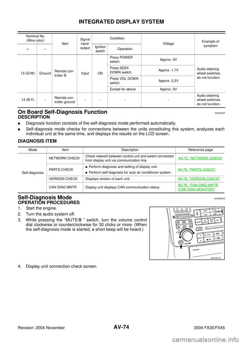
3. While pressing the “MUTE/II ” switch, turn the volume control
dial clockwise or counterclockwise for 30 clicks or more. (When
the self-diagnosis mode is started, a short beep will be heard.)
4. Display unit connection check screen.
13 (G/W) GroundRemote con-
troller BInput ONPress POWER
switch.Approx. 0V
Audio steering
wheel switches
do not function. Press SEEK
DOWN switch.Approx. 1.7V
Press VOL DOWN
switch.Approx. 3.3V
Except for above Approx. 5V
14 (B/Y) -Remote con-
troller ground-- - -Audio steering
wheel switches
do not function. Terminal No.
(Wire color)
ItemSignal
input/
outputCondition
VoltageExample of
symptom
+–Ignition
switchOperation
Mode Item Description Reference page
Self-diagnosisNETWORK CHECKCheck network between control unit and switch connected
from display unit via communication line.AV-75, "
NETWORK CHECK"
PARTS CHECK�Perform diagnosis and setting of display unit.
�Perform self-diagnosis for auto air conditioner system.AV- 7 6 , "PARTS CHECK"
VERSION CHECK Displays version of each unit.AV- 7 6 , "VERSION CHECK"
CAN DIAG MNTR Display unit displays CAN communication status.AV- 7 6 , "CAN DIAG MNTR
(CAN DIAG MONITOR)"
SKIA4971E