Page 1421 of 4449
EC-80
[VQ35DE]
TROUBLE DIAGNOSIS
Revision: 2004 November 2004 FX35/FX45
�Fuel filler cap was left off or incorrectly screwed on, allowing fuel to evaporate into the atmosphere.
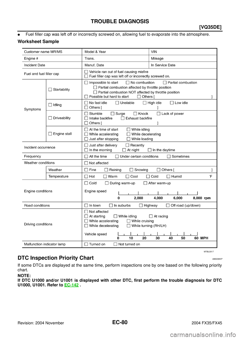
Worksheet Sample
DTC Inspection Priority ChartABS006KP
If some DTCs are displayed at the same time, perform inspections one by one based on the following priority
chart.
NOTE:
If DTC U1000 and/or U1001 is displayed with other DTC, first perform the trouble diagnosis for DTC
U1000, U1001. Refer to EC-142
.
MTBL0017
Page 1423 of 4449
![INFINITI FX35 2004 Service Manual EC-82
[VQ35DE]
TROUBLE DIAGNOSIS
Revision: 2004 November 2004 FX35/FX45
Fail-Safe ChartABS006KQ
When the DTC listed below is detected, the ECM enters fail-safe mode and the MIL lights up.
�When there](/manual-img/42/57021/w960_57021-1422.png "INFINITI FX35 2004 Service Manual EC-82
[VQ35DE]
TROUBLE DIAGNOSIS
Revision: 2004 November 2004 FX35/FX45
Fail-Safe ChartABS006KQ
When the DTC listed below is detected, the ECM enters fail-safe mode and the MIL lights up.
�When there")
EC-82
[VQ35DE]
TROUBLE DIAGNOSIS
Revision: 2004 November 2004 FX35/FX45
Fail-Safe ChartABS006KQ
When the DTC listed below is detected, the ECM enters fail-safe mode and the MIL lights up.
�When there is an open circuit on MIL circuit, the ECM cannot warn the driver by lighting MIL up when
there is malfunction on engine control system.
Therefore, when electrical controlled throttle and part of ECM related diagnoses are continuously detected
as NG for 5 trips, ECM warns the driver that engine control system malfunctions and MIL circuit is open by
means of operating fail-safe function.
The fail-safe function also operates when above diagnoses except MIL circuit are detected and demands
the driver to repair the malfunction.
DTC No. Detected items Engine operating condition in fail-safe mode
P0102
P0103Mass air flow sensor circuit Engine speed will not rise more than 2,400 rpm due to the fuel cut.
P0117
P0118Engine coolant tempera-
ture sensor circuitEngine coolant temperature will be determined by ECM based on the time after turning
ignition switch ON or START.
CONSULT-II displays the engine coolant temperature decided by ECM.
ConditionEngine coolant temperature decided
(CONSULT-II display)
Just as ignition switch is turned
ON or START40°C (104°F)
More than approx. 4 minutes after
ignition ON or START80°C (176°F)
Except as shown above40 - 80°C (104 - 176°F)
(Depends on the time)
When the fail-safe system for engine coolant temperature sensor is activated, the cooling
fan operates while engine is running.
P0122
P0123
P0222
P0223
P2135Throttle position sensor The ECM controls the electric throttle control actuator in regulating the throttle opening in
order for the idle position to be within +10 degrees.
The ECM regulates the opening speed of the throttle valve to be slower than the normal
condition.
So, the acceleration will be poor.
P1121 Electric throttle control
actuator(When electric throttle control actuator does not function properly due to the return spring
malfunction:)
ECM controls the electric throttle actuator by regulating the throttle opening around the
idle position. The engine speed will not rise more than 2,000 rpm.
(When throttle valve opening angle in fail-safe mode is not in specified range:)
ECM controls the electric throttle control actuator by regulating the throttle opening to 20
degrees or less.
(When ECM detects the throttle valve is stuck open:)
While the vehicle is driving, it slows down gradually by fuel cut. After the vehicle stops,
the engine stalls.
The engine can restart in N or P position, and engine speed will not exceed 1,000 rpm or
more.
P1122 Electric throttle control
functionECM stops the electric throttle control actuator control, throttle valve is maintained at a
fixed opening (approx. 5 degrees) by the return spring.
P1124
P1126Throttle control motor relay ECM stops the electric throttle control actuator control, throttle valve is maintained at a
fixed opening (approx. 5 degrees) by the return spring.
P1128 Throttle control motor ECM stops the electric throttle control actuator control, throttle valve is maintained at a
fixed opening (approx. 5 degrees) by the return spring.
P1229 Sensor power supply ECM stops the electric throttle control actuator control, throttle valve is maintained at a
fixed opening (approx. 5 degrees) by the return spring.
P2122
P2123
P2127
P2128
P2138Accelerator pedal position
sensorThe ECM controls the electric throttle control actuator in regulating the throttle opening in
order for the idle position to be within +10 degrees.
The ECM regulates the opening speed of the throttle valve to be slower than the normal
condition.
So, the acceleration will be poor.
Engine operating condition in fail-safe mode Engine speed will not rise more than 2,500 rpm due to the fuel cut
Page 1424 of 4449
![INFINITI FX35 2004 Service Manual TROUBLE DIAGNOSIS
EC-83
[VQ35DE]
C
D
E
F
G
H
I
J
K
L
MA
EC
Revision: 2004 November 2004 FX35/FX45
Basic InspectionABS006KR
1. INSPECTION START
1. Check service records for any recent repairs that may](/manual-img/42/57021/w960_57021-1423.png "INFINITI FX35 2004 Service Manual TROUBLE DIAGNOSIS
EC-83
[VQ35DE]
C
D
E
F
G
H
I
J
K
L
MA
EC
Revision: 2004 November 2004 FX35/FX45
Basic InspectionABS006KR
1. INSPECTION START
1. Check service records for any recent repairs that may")
TROUBLE DIAGNOSIS
EC-83
[VQ35DE]
C
D
E
F
G
H
I
J
K
L
MA
EC
Revision: 2004 November 2004 FX35/FX45
Basic InspectionABS006KR
1. INSPECTION START
1. Check service records for any recent repairs that may indicate a related malfunction, or a current need for
scheduled maintenance.
2. Open engine hood and check the following:
–Harness connectors for improper connections
–Wiring harness for improper connections, pinches and cut
–Vacuum hoses for splits, kinks and improper connections
–Hoses and ducts for leaks
–Air cleaner clogging
–Gasket
3. Confirm that electrical or mechanical loads are not applied.
–Headlamp switch is OFF.
–Air conditioner switch is OFF.
–Rear window defogger switch is OFF.
–Steering wheel is in the straight-ahead position, etc.
4. Start engine and warm it up until engine coolant temperature
indicator points the middle of gauge.
Ensure engine stays below 1,000 rpm.
5. Run engine at about 2,000 rpm for about 2 minutes under no-
load.
6. Make sure that no DTC is displayed with CONSULT-II or GST.
OK or NG
OK >> GO TO 3.
NG >> GO TO 2.
2. REPAIR OR REPLACE
Repair or replace components as necessary according to corresponding Diagnostic Procedure.
>> GO TO 3.
SEF983U
SEF976U
SEF977U
Page 1429 of 4449
![INFINITI FX35 2004 Service Manual EC-88
[VQ35DE]
TROUBLE DIAGNOSIS
Revision: 2004 November 2004 FX35/FX45
Symptom Matrix ChartABS006KS
SYSTEM — BASIC ENGINE CONTROL SYSTEM
SYMPTOM
Reference
page
HARD/NO START/RESTART (EXCP. HA)
ENG](/manual-img/42/57021/w960_57021-1428.png "INFINITI FX35 2004 Service Manual EC-88
[VQ35DE]
TROUBLE DIAGNOSIS
Revision: 2004 November 2004 FX35/FX45
Symptom Matrix ChartABS006KS
SYSTEM — BASIC ENGINE CONTROL SYSTEM
SYMPTOM
Reference
page
HARD/NO START/RESTART (EXCP. HA)
ENG")
EC-88
[VQ35DE]
TROUBLE DIAGNOSIS
Revision: 2004 November 2004 FX35/FX45
Symptom Matrix ChartABS006KS
SYSTEM — BASIC ENGINE CONTROL SYSTEM
SYMPTOM
Reference
page
HARD/NO START/RESTART (EXCP. HA)
ENGINE STALL
HESITATION/SURGING/FLAT SPOT
SPARK KNOCK/DETONATION
LACK OF POWER/POOR ACCELERATION
HIGH IDLE/LOW IDLE
ROUGH IDLE/HUNTING
IDLING VIBRATION
SLOW/NO RETURN TO IDLE
OVERHEATS/WATER TEMPERATURE HIGH
EXCESSIVE FUEL CONSUMPTION
EXCESSIVE OIL CONSUMPTION
BATTERY DEAD (UNDER CHARGE)
Warranty symptom code AA AB AC AD AE AF AG AH AJ AK AL AM HA
Fuel Fuel pump circuit 11232 22 3 2EC-603
Fuel pressure regulator system334444444 4EC-51
Injector circuit 11232 22 2EC-597
Evaporative emission system 334444444 4EC-643
Air Positive crankcase ventilation sys-
tem
334444444 41EC-655
Incorrect idle speed adjustment 1 1 1 1 1EC-38
Electric throttle control actuator 112332222 2 2EC-415,
EC-417
IgnitionIncorrect ignition timing adjustment33111 11 1EC-38
Ignition circuit 11222 22 2EC-585
Power supply and ground circuit22333 33 23EC-136
Mass air flow sensor circuit
1
122
222 2EC-165,
EC-173
Engine coolant temperature sensor circuit
333EC-185,
EC-197
Heated oxygen sensor 1 circuitEC-205
,
EC-214
,
EC-226
,
EC-433
,
EC-439
Throttle position sensor circuit
22EC-190
,
EC-284
,
EC-485
,
EC-487
,
EC-569
Accelerator pedal position sensor circuit 3 2 1EC-489
,
EC-555
,
EC-562
,
EC-576
Knock sensor circuit 2 3EC-297
Crankshaft position sensor (POS) circuit 2 2EC-302
Camshaft position sensor (PHASE) circuit 3 2EC-308
Vehicle speed signal circuit 2 3 3 3EC-390
Power steering pressure sensor circuit 2 3 3EC-396
Page 1430 of 4449
![INFINITI FX35 2004 Service Manual TROUBLE DIAGNOSIS
EC-89
[VQ35DE]
C
D
E
F
G
H
I
J
K
L
MA
EC
Revision: 2004 November 2004 FX35/FX45
1 - 6: The numbers refer to the order of inspection.
(continued on next page)
SYSTEM — ENGINE MECHAN](/manual-img/42/57021/w960_57021-1429.png "INFINITI FX35 2004 Service Manual TROUBLE DIAGNOSIS
EC-89
[VQ35DE]
C
D
E
F
G
H
I
J
K
L
MA
EC
Revision: 2004 November 2004 FX35/FX45
1 - 6: The numbers refer to the order of inspection.
(continued on next page)
SYSTEM — ENGINE MECHAN")
TROUBLE DIAGNOSIS
EC-89
[VQ35DE]
C
D
E
F
G
H
I
J
K
L
MA
EC
Revision: 2004 November 2004 FX35/FX45
1 - 6: The numbers refer to the order of inspection.
(continued on next page)
SYSTEM — ENGINE MECHANICAL & OTHER
ECM 22333333333EC-401,
EC-404
Intake valve timing control solenoid valve cir-
cuit32 13223 3EC-408
PNP switch circuit 3 3 3 3 3EC-545
Refrigerant pressure sensor circuit 2 3 3 4EC-609
Electrical load signal circuit 3EC-614
Air conditioner circuit223333333 3 2AT C - 4 0
ABS actuator and electric unit (control unit) 4BRC-12
SYMPTOM
Reference
page
HARD/NO START/RESTART (EXCP. HA)
ENGINE STALL
HESITATION/SURGING/FLAT SPOT
SPARK KNOCK/DETONATION
LACK OF POWER/POOR ACCELERATION
HIGH IDLE/LOW IDLE
ROUGH IDLE/HUNTING
IDLING VIBRATION
SLOW/NO RETURN TO IDLE
OVERHEATS/WATER TEMPERATURE HIGH
EXCESSIVE FUEL CONSUMPTION
EXCESSIVE OIL CONSUMPTION
BATTERY DEAD (UNDER CHARGE)
Warranty symptom code AA AB AC AD AE AF AG AH AJ AK AL AM HA
Fuel Fuel tank
5
5FL-10
Fuel piping 5 5 5 5 5 5EM-45
Vapor lock—
Valve deposit
5 555 55 5—
Poor fuel (Heavy weight gaso-
line, Low octane)—
Page 1433 of 4449
EC-92
[VQ35DE]
TROUBLE DIAGNOSIS
Revision: 2004 November 2004 FX35/FX45
Engine Control Component Parts LocationABS006KT
PBIB2002E
Page 1439 of 4449
EC-98
[VQ35DE]
TROUBLE DIAGNOSIS
Revision: 2004 November 2004 FX35/FX45
Circuit DiagramABS006KU
TBWH0101E
Page 1441 of 4449
![INFINITI FX35 2004 Service Manual EC-100
[VQ35DE]
TROUBLE DIAGNOSIS
Revision: 2004 November 2004 FX35/FX45
ECM Harness Connector Terminal LayoutABS006KV
ECM Terminals and Reference ValueABS006KW
PREPARATION
1. ECM is located behind th](/manual-img/42/57021/w960_57021-1440.png "INFINITI FX35 2004 Service Manual EC-100
[VQ35DE]
TROUBLE DIAGNOSIS
Revision: 2004 November 2004 FX35/FX45
ECM Harness Connector Terminal LayoutABS006KV
ECM Terminals and Reference ValueABS006KW
PREPARATION
1. ECM is located behind th")
EC-100
[VQ35DE]
TROUBLE DIAGNOSIS
Revision: 2004 November 2004 FX35/FX45
ECM Harness Connector Terminal LayoutABS006KV
ECM Terminals and Reference ValueABS006KW
PREPARATION
1. ECM is located behind the passenger side instrument lower
panel. For this inspection, remove passenger side instrument
lower panel.
2. Remove ECM harness connector.
3. When disconnecting ECM harness connector, loosen it with
levers as far as they will go as shown in the figure.
4. Connect a break-out box (SST) and Y-cable adapter (SST)
between the ECM and ECM harness connector.
�Use extreme care not to touch 2 pins at one time.
�Data is for comparison and may not be exact.
ECM INSPECTION TABLE
Specification data are reference values and are measured between each terminal and ground.
Pulse signal is measured by CONSULT-II.
CAUTION:
Do not use ECM ground terminals when measuring input/output voltage. Doing so may result in dam-
age to the ECMs transistor. Use a ground other than ECM terminals, such as the ground.
PBIB1192E
PBIB1578E
PBIB1512E
TER-
MINAL
NO.WIRE
COLORITEM CONDITION DATA (DC Voltage)
1 B ECM ground[Engine is running]
�Idle speedBody ground
![INFINITI FX35 2004 Service Manual EC-92
[VQ35DE]
TROUBLE DIAGNOSIS
Revision: 2004 November 2004 FX35/FX45
Engine Control Component Parts LocationABS006KT
PBIB2002E](/manual-img/42/57021/w960_57021-1432.png "INFINITI FX35 2004 Service Manual EC-92
[VQ35DE]
TROUBLE DIAGNOSIS
Revision: 2004 November 2004 FX35/FX45
Engine Control Component Parts LocationABS006KT
PBIB2002E")
![INFINITI FX35 2004 Service Manual EC-98
[VQ35DE]
TROUBLE DIAGNOSIS
Revision: 2004 November 2004 FX35/FX45
Circuit DiagramABS006KU
TBWH0101E](/manual-img/42/57021/w960_57021-1438.png "INFINITI FX35 2004 Service Manual EC-98
[VQ35DE]
TROUBLE DIAGNOSIS
Revision: 2004 November 2004 FX35/FX45
Circuit DiagramABS006KU
TBWH0101E")