Page 949 of 4449
BL-142
INTELLIGENT KEY SYSTEM
Revision: 2004 November 2004 FX35/FX45
3. STOP LAMP SWITCH GROUND CIRCUIT INSPECTION
1. Check continuity between stop lamp switch connector E210 ter-
minal 2 (P) and Intelligent Key unit connector M34 terminal 26
(P/L).
2. Check continuity between stop lamp switch connector E210 ter-
minal 2 (P) and ground.
OK or NG
OK >> Stop lamp switch is OK.
NG >> Repair or replace harness.
Check Detention SwitchAIS004NN
1. DETENTION SWITCH INPUT SIGNAL INSPECTION
1. Turn ignition knob LOCK position.
2. Check voltage between Intelligent Key unit connector and ground.
OK or NG
OK >> Door switch circuit is OK.
NG >> GO TO 2.2 (P) - 26 (P/L) : Continuity should exist.
2 (P) - Ground : Continuity should not exist.
PIIA6801E
ConnectorTerminal
(Wire color)
ConditionVoltage (V)
(Approx.)
(+) (-)
M34 39 (R/Y) GroundWhen selector lever is locked
at the “P” position0
When selector lever is not
locked at the “P” positionBattery voltage
PIIA6805E
Page 950 of 4449
INTELLIGENT KEY SYSTEM
BL-143
C
D
E
F
G
H
J
K
L
MA
B
BL
Revision: 2004 November 2004 FX35/FX45
2. DETENTION SWITCH CIRCUIT INSPECTION
1. Disconnect A/T device (detention switch) connector.
2. Check voltage between A/T device (detention switch) connector
M67 terminal 3 (R/Y) and ground. (Check harness for open.)
3. Check continuity between A/T device (detention switch) connec-
tor M67 terminals 3 (R/Y) and ground. (Check harness for
short.)
OK or NG
OK >> GO TO 3.
NG >> Repair or replace harness.
3. DETENTION SWITCH INSPECTION
Check continuity between A/T device (detention switch) terminals 2 and 3.
OK or NG
OK >> GO TO 4.
NG >> Replace back A/T device (detention switch).3 (R/Y) – Ground : Battery voltage
PIIA6806E
3 (R/Y) – Ground : Continuity should not exist.
PIIA6807E
Terminal Condition Continuity
2 – 3When selector lever is not
locked at the “P” positionNo
When selector lever is
locked at the “P” positionYe s
PIIA6808E
Page 951 of 4449

BL-144
INTELLIGENT KEY SYSTEM
Revision: 2004 November 2004 FX35/FX45
4. DETENTION SWITCH GROUND CIRCUIT INSPECTION
Check continuity between A/T device (detention switch) connector
M67 terminal 2 (B) and ground.
OK or NG
OK >> Check harness connection.
NG >> Repair or replace harness.
Check Select Unlock RelayAIS004NO
1. CHECK SELECT UNLOCK RELAY POWER SUPPLY
1. Turn ignition switch OFF.
2. Disconnect passenger side select unlock relay connector.
3. Check voltage between passenger side select unlock relay con-
nector M30 terminal 1 and ground.
OK or NG
OK >> GO TO 2.
NG >> Repair or replace passenger side select unlock relay power supply circuit.
2. CHECK HARNESS
1. Disconnect Intelligent Key unit connector.
2. Check continuity between passenger side select unlock relay
connector M30 terminal 2 and Intelligent Key unit connector
M34 terminal 40.
3. Check continuity between passenger side select unlock relay
connector M30 terminal 2 and ground.
OK or NG
OK >> Replace passenger side select unlock relay.
NG >> Repair or replace harness between passenger side select unlock relay and Intelligent Key unit.2 (B) – Ground : Continuity should exist.
PIIA6809E
1 (L/R) – Ground : Approx. 12V
PIIA6954E
2 (BR/W) – 40 (BR/W) : Continuity should exist.
2 (BR/W) – Ground : Continuity should not exist.
PIIA6955E
Page 952 of 4449

INTELLIGENT KEY SYSTEM
BL-145
C
D
E
F
G
H
J
K
L
MA
B
BL
Revision: 2004 November 2004 FX35/FX45
Check Hazard FunctionAIS004NP
1. CHECK HAZARD WARNING LAMP
Does hazard warning lamp flash with hazard switch?
YES or NO
YES >> Hazard warning lamp circuit is OK.
NO >> Check hazard circuit. Refer to LT- 8 9 , "
TURN SIGNAL AND HAZARD WARNING LAMPS" .
Check Horn FunctionAIS004NQ
First perform the “SELF-DIAG RESULTS” in “BCM” with CONSULT-II, then perform the trouble diagnosis of
malfunction system indicated “SELF-DIAG RESULTS” of “BCM”. Refer to BCS-14, "
CAN Communication
Inspection Using CONSULT-II (Self-Diagnosis)" .
1. CHECK HORN FUNCTION
Does horn sound with horn switch?
YES or NO
YES >> Horn circuit is OK.
NO >> Check horn circuit. Refer to WW-56, "
HORN" .
Check Headlamp FunctionAIS004NR
First perform the “SELF-DIAG RESULTS” in “BCM” with CONSULT-II, then perform the trouble diagnosis of
malfunction system indicated “SELF-DIAG RESULTS” of “BCM”. Refer to BCS-14, "
CAN Communication
Inspection Using CONSULT-II (Self-Diagnosis)" .
1. CHECK HEADLAMP OPERATION
Does headlamp come on when turning lighting switch “ON”?
YES or NO
YES >> Headlamp operation circuit is OK.
NO >> Check headlamp system. Refer to LT- 7 , "
HEADLAMP - XENON TYPE -" .
Check IPDM E/R OperationAIS004NS
1. CHECK IPDM E/R INPUT VOLTAGE
Check voltage between IPDM E/R connector E9 terminal 51 (SB) and ground.
OK or NG
OK >> Replace IPDM E/R.
NG >> GO TO 2.51 (SB) – Ground : Battery voltage
PIIA6403E
Page 953 of 4449
BL-146
INTELLIGENT KEY SYSTEM
Revision: 2004 November 2004 FX35/FX45
2. CHECK IPDM E/R HARNESS
1. Turn ignition switch OFF.
2. Disconnect IPDM E/R and horn relay connector.
3. Check continuity between IPDM E/R connector E9 terminal 51 (SB) and horn relay connector E10 termi-
nal 1 (SB).
OK or NG
OK >> Check harness connection.
NG >> Repair or replace harness.
Removal and Installation of Intelligent Key UnitAIS004NT
REMOVAL
1. Remove the instrument lower driver panel. Refer to IP-11, "Removal and Installation" .
2. Disconnect the Intelligent Key unit connector, remove the screw
and Intelligent Key unit.
INSTALLATION
Install in the reverse order of removal.51 (SB) – 1 (SB) : Continuity should exist.
PIIA6404E
PIIA6371E
Page 954 of 4449

INTELLIGENT KEY SYSTEM
BL-147
C
D
E
F
G
H
J
K
L
MA
B
BL
Revision: 2004 November 2004 FX35/FX45
Intelligent Key InspectionAIS004NU
INTELLIGENT KEY DISASSEMBLY AND ASSEMBLY
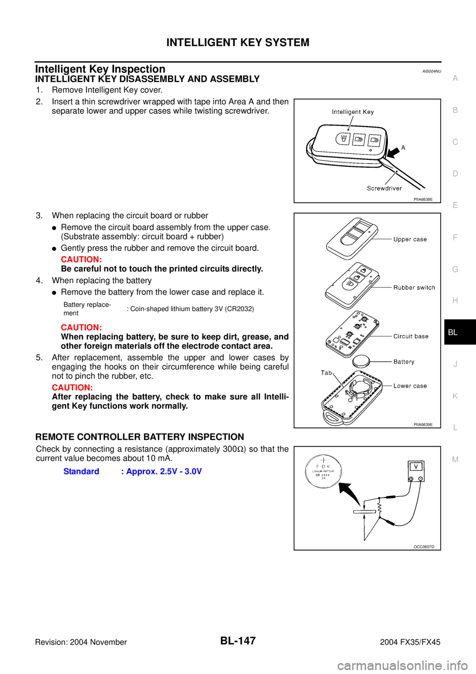
1. Remove Intelligent Key cover.
2. Insert a thin screwdriver wrapped with tape into Area A and then
separate lower and upper cases while twisting screwdriver.
3. When replacing the circuit board or rubber
�Remove the circuit board assembly from the upper case.
(Substrate assembly: circuit board + rubber)
�Gently press the rubber and remove the circuit board.
CAUTION:
Be careful not to touch the printed circuits directly.
4. When replacing the battery
�Remove the battery from the lower case and replace it.
CAUTION:
When replacing battery, be sure to keep dirt, grease, and
other foreign materials off the electrode contact area.
5. After replacement, assemble the upper and lower cases by
engaging the hooks on their circumference while being careful
not to pinch the rubber, etc.
CAUTION:
After replacing the battery, check to make sure all Intelli-
gent Key functions work normally.
REMOTE CONTROLLER BATTERY INSPECTION
Check by connecting a resistance (approximately 300Ω) so that the
current value becomes about 10 mA.
PIIA6638E
Battery replace-
ment: Coin-shaped lithium battery 3V (CR2032)
PIIA6639E
Standard : Approx. 2.5V - 3.0V
OCC0607D
Page 959 of 4449

BL-152
FRONT DOOR LOCK
Revision: 2004 November 2004 FX35/FX45
FRONT DOOR LOCKPFP:80502
Removal and InstallationAIS004NZ
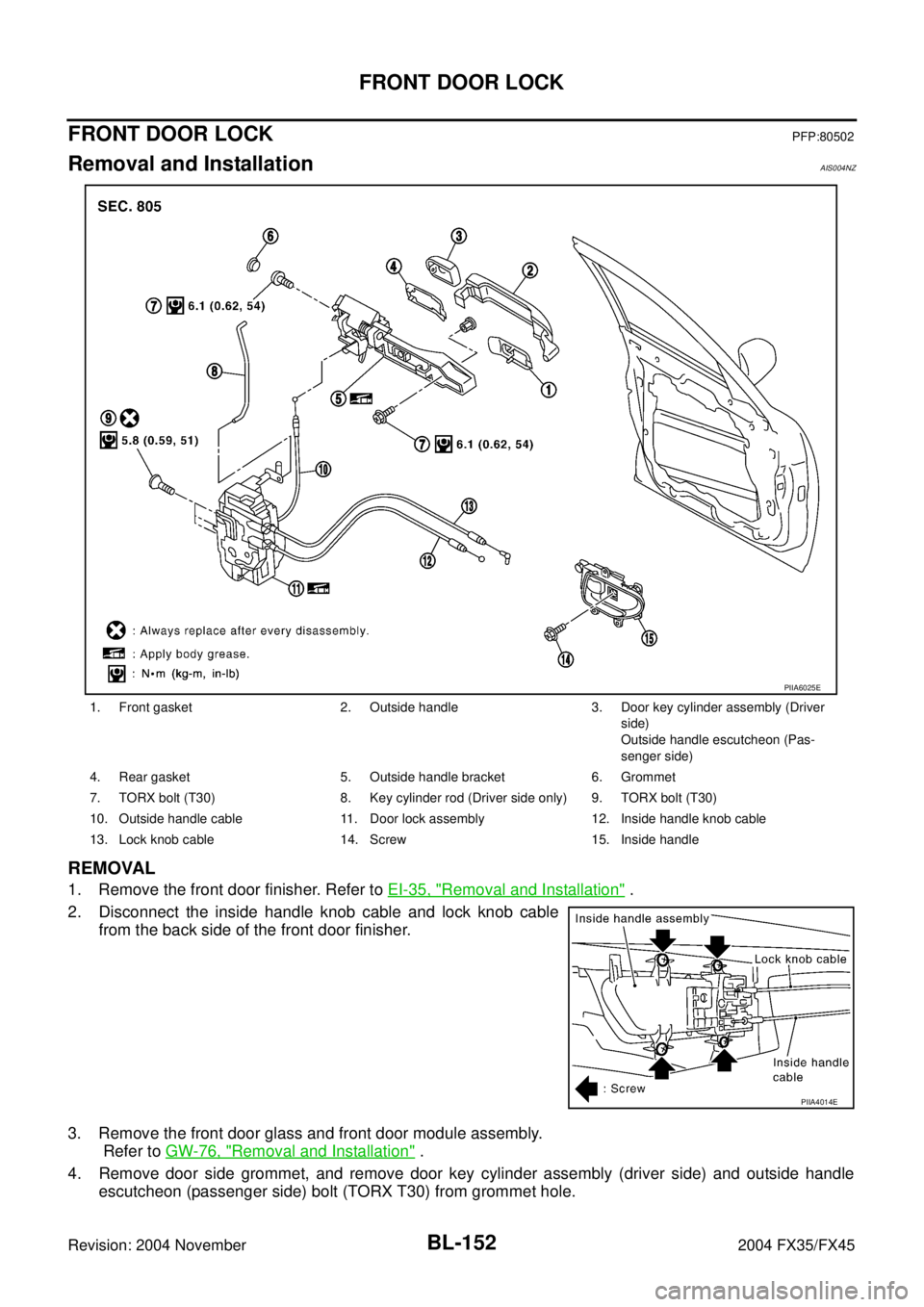
REMOVAL
1. Remove the front door finisher. Refer to EI-35, "Removal and Installation" .
2. Disconnect the inside handle knob cable and lock knob cable
from the back side of the front door finisher.
3. Remove the front door glass and front door module assembly.
Refer to GW-76, "
Removal and Installation" .
4. Remove door side grommet, and remove door key cylinder assembly (driver side) and outside handle
escutcheon (passenger side) bolt (TORX T30) from grommet hole.
1. Front gasket 2. Outside handle 3. Door key cylinder assembly (Driver
side)
Outside handle escutcheon (Pas-
senger side)
4. Rear gasket 5. Outside handle bracket 6. Grommet
7. TORX bolt (T30) 8. Key cylinder rod (Driver side only) 9. TORX bolt (T30)
10. Outside handle cable 11. Door lock assembly 12. Inside handle knob cable
13. Lock knob cable 14. Screw 15. Inside handle
PIIA6025E
PIIA4014E
Page 960 of 4449
FRONT DOOR LOCK
BL-153
C
D
E
F
G
H
J
K
L
MA
B
BL
Revision: 2004 November 2004 FX35/FX45
CAUTION:
Do not forcibly remove the TORX bolt (T30).
5. Reach to separate the key cylinder rod connection (on the handle).
6. While pulling the outside handle, remove door key cylinder
assembly (driver side) and outside handle escutcheon (passen-
ger side).
7. Disconnect the door request switch connector. (intelligent key only)
8. While pulling outside handle, slide toward rear of vehicle to
remove outside handle.
9. Remove the front gasket and rear gasket.
PIIA3553E
PIIA3554E
PIIA3555E
PIIA3557E