Page 2747 of 4449
![INFINITI FX35 2004 Service Manual EM-22
[VQ35DE]
INTAKE MANIFOLD COLLECTOR
Revision: 2004 November 2004 FX35/FX45
INSTALLATION
Note to the following, and install in the reverse order of removal.
Part Installation Direction
Referring t](/manual-img/42/57021/w960_57021-2746.png "INFINITI FX35 2004 Service Manual EM-22
[VQ35DE]
INTAKE MANIFOLD COLLECTOR
Revision: 2004 November 2004 FX35/FX45
INSTALLATION
Note to the following, and install in the reverse order of removal.
Part Installation Direction
Referring t")
EM-22
[VQ35DE]
INTAKE MANIFOLD COLLECTOR
Revision: 2004 November 2004 FX35/FX45
INSTALLATION
Note to the following, and install in the reverse order of removal.
Part Installation Direction
Referring to front marks, install parts shown in figure.
Intake Manifold Collector (Lower)
Tighten in numerical order as shown in the figure.
NOTE:
Tighten mounting bolts to secure gasket (lower), intake manifold col-
lector (lower), gasket (upper), and intake manifold collector cover.
Intake Manifold Collector (Upper)
�If stud bolts were removed, install them and tighten to the speci-
fied torque below.
�Shank length under bolt head varies with bolt location. Install
bolts while referring to numbers shown below and in figure. (Bolt
length does not include pilot portion.)
�Tighten in numerical order as shown in the figure.
Water Hose
�Insert hose by 27 to 32 mm (1.06 to 1.26 in) from connector end.
PBIC0776E
PBIC0774E
: 5.9 N·m (0.6 kg-m, 52 in-lb)
Bolt
M6 × 25 mm (0.98 in) : 7, 8, 10, 11, 13, 14, 15, 16, 18
M6 × 45 mm (1.77 in) : 2, 4, 5
M6 × 60 mm (2.36 in) : 1, 3, 6, 9
M6 Nut : 12, 17
PBIC0773E
Page 2750 of 4449
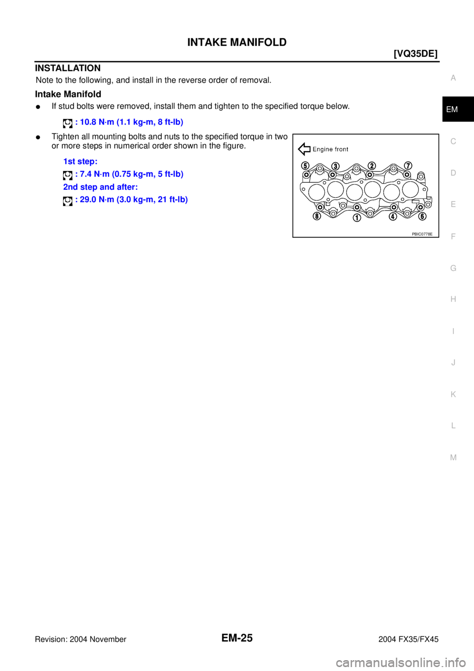
INTAKE MANIFOLD
EM-25
[VQ35DE]
C
D
E
F
G
H
I
J
K
L
MA
EM
Revision: 2004 November 2004 FX35/FX45
INSTALLATION
Note to the following, and install in the reverse order of removal.
Intake Manifold
�If stud bolts were removed, install them and tighten to the specified torque below.
�Tighten all mounting bolts and nuts to the specified torque in two
or more steps in numerical order shown in the figure. : 10.8 N·m (1.1 kg-m, 8 ft-lb)
1st step:
: 7.4 N·m (0.75 kg-m, 5 ft-lb)
2nd step and after:
: 29.0 N·m (3.0 kg-m, 21 ft-lb)
PBIC0778E
Page 2753 of 4449
![INFINITI FX35 2004 Service Manual EM-28
[VQ35DE]
EXHAUST MANIFOLD AND THREE WAY CATALYST
Revision: 2004 November 2004 FX35/FX45
INSPECTION AFTER REMOVAL
Surface Distortion
�Check the surface distortion of the exhaust manifold mating s](/manual-img/42/57021/w960_57021-2752.png "INFINITI FX35 2004 Service Manual EM-28
[VQ35DE]
EXHAUST MANIFOLD AND THREE WAY CATALYST
Revision: 2004 November 2004 FX35/FX45
INSPECTION AFTER REMOVAL
Surface Distortion
�Check the surface distortion of the exhaust manifold mating s")
EM-28
[VQ35DE]
EXHAUST MANIFOLD AND THREE WAY CATALYST
Revision: 2004 November 2004 FX35/FX45
INSPECTION AFTER REMOVAL
Surface Distortion
�Check the surface distortion of the exhaust manifold mating sur-
face with straightedge and feeler gauge.
�If it exceeds the limit, replace exhaust manifold.
INSTALLATION
Note to the following, and install in the reverse order of removal.
Exhaust Manifold Gasket
�Install in direction shown below. (Follow same procedure for
both banks.)
�Locate thick side of port connecting part on right side from tech-
nician’s view.
�Locate round press in thick side of port connecting part above
center level line of port.
Exhaust Manifold
�If stud bolts were removed, install them and tighten to the speci-
fied torque below.
�Install exhaust manifold in the numerical order as shown in the
figure.
NOTE:
Tighten nuts No. 1 and No. 2 in two steps. The numerical order
No. 7 and No. 8 shows second step.
Heated Oxygen Sensor
CAUTION:
�Before installing a new heated oxygen sensor, clean exhaust system threads using heated oxygen
sensor thread cleaner tool (Commercial Service Tool: J-43897-18 or J-43897-12) and apply anti-
seize lubricant.Limit : 0.3 mm (0.012 in)
PBIC1096E
KBIA1051E
: 14.7 N·m (1.5 kg-m, 11 ft-lb)
PBIC2042E
Page 2754 of 4449
EXHAUST MANIFOLD AND THREE WAY CATALYST
EM-29
[VQ35DE]
C
D
E
F
G
H
I
J
K
L
MA
EM
Revision: 2004 November 2004 FX35/FX45
�Do not over torque heated oxygen sensor. Doing so may cause damage to heated oxygen sensor,
resulting in the “MIL” coming on.
Page 2785 of 4449
![INFINITI FX35 2004 Service Manual EM-60
[VQ35DE]
FRONT TIMING CHAIN CASE
Revision: 2004 November 2004 FX35/FX45
�Apply liquid gasket to top surface of oil pan (upper) as shown
in the figure with tube presser [SST: WS39930000 ( – )].](/manual-img/42/57021/w960_57021-2784.png "INFINITI FX35 2004 Service Manual EM-60
[VQ35DE]
FRONT TIMING CHAIN CASE
Revision: 2004 November 2004 FX35/FX45
�Apply liquid gasket to top surface of oil pan (upper) as shown
in the figure with tube presser [SST: WS39930000 ( – )].")
EM-60
[VQ35DE]
FRONT TIMING CHAIN CASE
Revision: 2004 November 2004 FX35/FX45
�Apply liquid gasket to top surface of oil pan (upper) as shown
in the figure with tube presser [SST: WS39930000 ( – )].
Use Genuine RTV Silicone Sealant or equivalent. Refer to
GI-48, "
RECOMMENDED CHEMICAL PRODUCTS AND
SEALANTS".
c. Install new O-rings on rear timing chain case.
d. Assemble front timing chain case as follows.
i. Fit lower end of front timing chain case tightly onto top face of oil
pan (upper). From the fitting point, make entire front timing chain
case contact rear timing chain case completely.
CAUTION:
Be careful that oil pan gasket is in place.
ii. While pressing front timing chain case from its front and top as
shown in the figure, install bolts and temporarily tighten them.
For bolt length and positions, refer to the step 6.
iii. Hammer dowel pin until the outer end becomes flush with sur-
face.
6. Tighten bolts to the specified torque in order as shown in the fig-
ure.
�After tightening, retighten them to specified torque in numeri-
cal order as shown in the figure.
PBIC1099E
SBIA0497E
PBIC1100E
PBIC1115E
8 mm (0.31 in) dia. bolts : 1, 2
: 28.4 N·m (2.9 kg-m, 21 ft-lb)
6 mm (0.24 in) dia. bolts : Except the above
: 12.7 N·m (1.3 kg-m, 9 ft-lb)
KBIA1303E
Page 2804 of 4449
![INFINITI FX35 2004 Service Manual TIMING CHAIN
EM-79
[VQ35DE]
C
D
E
F
G
H
I
J
K
L
MA
EM
Revision: 2004 November 2004 FX35/FX45
19. Install front timing chain case as follows:
a. Apply liquid gasket to front timing chain case back side](/manual-img/42/57021/w960_57021-2803.png "INFINITI FX35 2004 Service Manual TIMING CHAIN
EM-79
[VQ35DE]
C
D
E
F
G
H
I
J
K
L
MA
EM
Revision: 2004 November 2004 FX35/FX45
19. Install front timing chain case as follows:
a. Apply liquid gasket to front timing chain case back side")
TIMING CHAIN
EM-79
[VQ35DE]
C
D
E
F
G
H
I
J
K
L
MA
EM
Revision: 2004 November 2004 FX35/FX45
19. Install front timing chain case as follows:
a. Apply liquid gasket to front timing chain case back side as
shown in the figure with tube presser [SST: WS39930000 ( – )].
Use Genuine RTV Silicone Sealant or equivalent. Refer to
GI-48, "
RECOMMENDED CHEMICAL PRODUCTS AND
SEALANTS".
b. Install dowel pin on rear timing chain case into dowel pin hole on
front timing chain case.
c. Tighten bolts to the specified torque in order as shown in the fig-
ure.
d. After tightening, retighten them to specified torque in numerical
order shown in figure.
20. After installing front timing chain case, check the surface height
difference between the following parts on the oil pan mounting
surface.
�If not within specification, repeat the installation procedure.
21. Install right and left intake valve timing control covers as follows:
a. Install seal rings in shaft grooves.
b. Apply liquid gasket to intake valve timing control covers as
shown in the figure with tube presser [SST: WS39930000 ( – )].
Use Genuine RTV Silicone Sealant or equivalent. Refer to
GI-48, "
RECOMMENDED CHEMICAL PRODUCTS AND
SEALANTS".
PBIC1133E
8 mm (0.31 in) dia. bolts : 1, 2
: 28.4 N·m (2.9 kg-m, 21 ft-lb)
6 mm (0.24 in) dia. bolts : Except the above
: 12.7 N·m (1.3 kg-m, 9 ft-lb)
KBIA1303E
Standard
Front timing chain case to rear timing chain case:
–0.14 to 0.14 mm (–0.005 to 0.0055 in)
SEM943G
SBIA0492E
Page 2809 of 4449
![INFINITI FX35 2004 Service Manual EM-84
[VQ35DE]
CAMSHAFT
Revision: 2004 November 2004 FX35/FX45
7. Remove secondary timing chain tensioner from cylinder head.
�Remove chain tensioner with its stopper pin attached.
NOTE:
Stopper pin w](/manual-img/42/57021/w960_57021-2808.png "INFINITI FX35 2004 Service Manual EM-84
[VQ35DE]
CAMSHAFT
Revision: 2004 November 2004 FX35/FX45
7. Remove secondary timing chain tensioner from cylinder head.
�Remove chain tensioner with its stopper pin attached.
NOTE:
Stopper pin w")
EM-84
[VQ35DE]
CAMSHAFT
Revision: 2004 November 2004 FX35/FX45
7. Remove secondary timing chain tensioner from cylinder head.
�Remove chain tensioner with its stopper pin attached.
NOTE:
Stopper pin was attached when secondary timing chain was
removed.
INSPECTION AFTER REMOVAL
Camshaft Runout
1. Put V block on precise flat bed, and support No. 2 and No. 4
journal of camshaft.
CAUTION:
Do not support journal No. 1 (on the side of camshaft
sprocket) because it has a different diameter from the other
three locations.
2. Set dial gauge vertically to No. 3 journal.
3. Turn camshaft to one direction with hands, and measure cam-
shaft runout on dial gauge. (Total indicator reading)
4. If it exceeds the standard, replace camshaft.
Camshaft Cam Height
1. Measure camshaft cam height.
2. If wear is beyond the limit, replace camshaft.
Camshaft Journal Oil Clearance
Outer Diameter of Camshaft Journal
Measure outer diameter of camshaft journal.
Inner Diameter of Camshaft Bracket
�Tighten camshaft bracket bolt with specified torque. Refer to EM-87, "INSTALLATION" .
SBIA0499E
Standard : Less than 0.05 mm (0.0020 in)PBIC0929E
Standard cam height (intake and exhaust)
: 44.865 - 45.055 mm (1.7663 - 1.7738 in)
Cam wear limit
: 0.2 mm (0.008 in)
EMQ0072D
Standard outer diameter:
No. 1: 25.935 - 25.955 mm (1.0211 - 1.0218 in)
No. 2, 3, 4: 23.445 - 23.465 mm (0.9230 - 0.9238 in)
PBIC0040E
Page 2837 of 4449
![INFINITI FX35 2004 Service Manual EM-112
[VQ35DE]
ENGINE ASSEMBLY
Revision: 2004 November 2004 FX35/FX45
a. Remove passenger-side kicking plate, dash side finisher, and
glove box. Refer to EI-37, "
BODY SIDE TRIM" and IP-10,
"INSTRUM](/manual-img/42/57021/w960_57021-2836.png "INFINITI FX35 2004 Service Manual EM-112
[VQ35DE]
ENGINE ASSEMBLY
Revision: 2004 November 2004 FX35/FX45
a. Remove passenger-side kicking plate, dash side finisher, and
glove box. Refer to EI-37, \"
BODY SIDE TRIM\" and IP-10,
\"INSTRUM")
EM-112
[VQ35DE]
ENGINE ASSEMBLY
Revision: 2004 November 2004 FX35/FX45
a. Remove passenger-side kicking plate, dash side finisher, and
glove box. Refer to EI-37, "
BODY SIDE TRIM" and IP-10,
"INSTRUMENT PANEL ASSEMBLY" .
b. Disconnect engine room harness connectors at unit sides ECM
and other.
c. Disengage intermediate fixing point. Pull out engine room har-
nesses to engine room side, and temporarily secure them on
engine.
CAUTION:
�When pulling out harnesses, take care not to damage
harnesses and connectors.
�After temporarily securing, cover connectors with vinyl or similar material to protect against for-
eign material adhesion.
Vehicle Underbody
1. Remove A/T fluid cooler hoses and power steering oil pump oil cooler hoses.
2. Remove exhaust front tube. Refer to EX-3, "
EXHAUST SYSTEM" .
3. Disconnect steering lower joint, and release steering shaft. Refer to PS-12, "
STEERING COLUMN" .
4. Separate transmission and propeller shaft. Refer to PR-6, "
REAR PROPELLER SHAFT" .
5. Disengage shift control linkage at selector lever side. Then, temporarily secure it on transmission, so that
it does not sag.
6. Remove rear plate cover from upper oil pan. Then, remove bolts fixing drive plate to torque converter.
7. Remove bolts fixing transmission to lower rear side of upper oil pan.
8. Remove front stabilizer. Refer to FSU-6, "
FRONT SUSPENSION ASSEMBLY" .
9. Remove LH and RH sides tie-rod ends from steering knuckle. Refer to FSU-6, "
FRONT SUSPENSION
ASSEMBLY" .
10. Remove lower ends of LH and RH sides struts from lower arms. Refer to FSU-6, "
FRONT SUSPENSION
ASSEMBLY" .
11. Remove LH and RH sides lower arms from suspension member. Refer to FSU-6, "
FRONT SUSPENSION
ASSEMBLY" .
Removal Work
1. Use a manual lift table caddy (commercial service tool) or equiv-
alently rigid tool such as a transmission jack. Securely support
bottom of suspension member and transmission.
CAUTION:
Put a piece of wood or something similar as the supporting
surface, secure a completely stable condition.
2. Remove rear member mounting bolt.
3. Remove suspension member mounting bolt and nut. Refer to
FSU-6, "
FRONT SUSPENSION ASSEMBLY" .
4. Carefully lower jack to remove engine, transmission, and sus-
pension member assembly. When performing work, observe the
following:
CAUTION:
�Confirm there is no interference with vehicle.
�Make sure all connection points have been disconnected.
�Keep in mind the center of vehicle gravity changes. If necessary, use jack(s) to support vehicle
at rear jacking point(s) to prevent it from falling it off lift.
SBIA0473E
PBIC0804E