Page 3020 of 4449
![INFINITI FX35 2004 Service Manual FRONT WHEEL HUB AND KNUCKLE
FAX-11
[AWD]
C
E
F
G
H
I
J
K
L
MA
B
FA X
Revision: 2004 November 2004 FX35/FX45
6. Use a ball joint remover (SST) to remove steering outer socket
from steering knuckle. Be](/manual-img/42/57021/w960_57021-3019.png "INFINITI FX35 2004 Service Manual FRONT WHEEL HUB AND KNUCKLE
FAX-11
[AWD]
C
E
F
G
H
I
J
K
L
MA
B
FA X
Revision: 2004 November 2004 FX35/FX45
6. Use a ball joint remover (SST) to remove steering outer socket
from steering knuckle. Be")
FRONT WHEEL HUB AND KNUCKLE
FAX-11
[AWD]
C
E
F
G
H
I
J
K
L
MA
B
FA X
Revision: 2004 November 2004 FX35/FX45
6. Use a ball joint remover (SST) to remove steering outer socket
from steering knuckle. Be careful not to damage ball joint boot.
CAUTION:
Tighten temporarily mounting nut to prevent damage to
threads and to prevent ball joint remover (SST) from com-
ing off.
7. Remove cotter pin at transverse link, then loosen mounting nut.
8. Use a ball joint remover (SST) to remove transverse link from
steering knuckle. Be careful not to damage ball joint boot.
CAUTION:
Tighten temporarily mounting nut to prevent damage to
threads and to prevent ball joint remover (SST) from com-
ing off.
9. Remove cotter pin, then remove lock nut from drive shaft with
power tool.
10. Remove steering knuckle from drive shaft.
CAUTION:
�When removing steering knuckle, do not apply an exces-
sive angle to drive shaft joint. Also be careful not to excessively extend slide joint.
�Do not hang over drive shaft without support.
11. Remove fixing bolts and nuts between strut assembly and steering knuckle with power tool.
12. Remove steering knuckle from vehicle.
13. Remove fixing bolts between steering knuckle and wheel hub and bearing assembly with power tool.
14. Remove splash guard and wheel hub and bearing assembly from steering knuckle.
INSPECTION AFTER REMOVAL
Check for deformity, cracks and damage on each parts, replace if necessary.
Ball Joint Inspection
Check for boot breakage, axial looseness, and torque of transverse link and steering outer socket ball joint.
Refer to FSU-14, "
TRANSVERSE LINK" , PS-19, "POWER STEERING GEAR AND LINKAGE" .
INSTALLATION
�Refer to FAX-10, "Removal and Installation" for tightening torque. Install in the reverse order of removal.
NOTE:
Refer to component parts location and do not reuse non-reusable parts.
�After removing/installing or replacing axle components, check wheel alignment. Refer to FSU-6, "Wheel
Alignment Inspection" .
�After adjusting wheel alignment, adjust neutral position of steering angle sensor. Refer to BRC-6, "Adjust-
ment of Steering Angle Sensor Neutral Position" .
�Check the following item after service.
–Installation condition of wheel sensor harness.
SDIA1434E
SDIA1435E
Page 3021 of 4449
![INFINITI FX35 2004 Service Manual FAX-12
[AWD]
FRONT DRIVE SHAFT
Revision: 2004 November 2004 FX35/FX45
FRONT DRIVE SHAFTPFP:39100
Removal and Installation (Left Side)ADS000ON
REMOVAL
1. Remove tire from vehicle with power tool.
2. Re](/manual-img/42/57021/w960_57021-3020.png "INFINITI FX35 2004 Service Manual FAX-12
[AWD]
FRONT DRIVE SHAFT
Revision: 2004 November 2004 FX35/FX45
FRONT DRIVE SHAFTPFP:39100
Removal and Installation (Left Side)ADS000ON
REMOVAL
1. Remove tire from vehicle with power tool.
2. Re")
FAX-12
[AWD]
FRONT DRIVE SHAFT
Revision: 2004 November 2004 FX35/FX45
FRONT DRIVE SHAFTPFP:39100
Removal and Installation (Left Side)ADS000ON
REMOVAL
1. Remove tire from vehicle with power tool.
2. Remove undercover with power tool.
3. Remove cotter pin. Then remove lock nut from drive shaft with power tool.
4. Remove wheel sensor harness from strut assembly. Refer to BRC-57, "
WHEEL SENSORS" .
CAUTION:
Do not pull on wheel sensor harness.
5. Remove brake hose lock plate. Then remove brake hose from strut assembly. Refer to BR-11, "
BRAKE
PIPING AND HOSE" .
6. Remove fixing bolts and nuts between strut assembly and steering knuckle with power tool.
7. Remove drive shaft from steering knuckle.
CAUTION:
When removing drive shaft, do not apply an excessive angle to drive shaft joint. Also be careful
not to excessively extend slide joint.
8. Remove fixing bolt of front final drive side assembly drive shaft with power tool, then remove drive shaft
from vehicle.
INSPECTION AFTER REMOVAL
�Move joint up/down, left /right, and in the axial direction. Check for any rough movement or significant
looseness.
�Check boot for cracks or other damage, and also for grease
leakage.
�If a trouble is found, disassemble drive shaft, and then replace
with new one.
INSTALLATION
�Refer to FA X - 1 2 , "Removal and Installation (Left Side)" for tightening torque. Install in the reverse order of
removal.
NOTE:
Refer to component parts location and do not reuse non-reusable parts.
�Check the following item after service.
–Installation condition of wheel sensor harness
1. Cotter pin 2. Washer
SDIA1441E
SDIA1046J
Page 3023 of 4449
![INFINITI FX35 2004 Service Manual FAX-14
[AWD]
FRONT DRIVE SHAFT
Revision: 2004 November 2004 FX35/FX45
INSTALLATION
�Refer to FAX-13, "Removal and Installation (Right Side)" for tightening torque. Install in the reverse order
of rem](/manual-img/42/57021/w960_57021-3022.png "INFINITI FX35 2004 Service Manual FAX-14
[AWD]
FRONT DRIVE SHAFT
Revision: 2004 November 2004 FX35/FX45
INSTALLATION
�Refer to FAX-13, \"Removal and Installation (Right Side)\" for tightening torque. Install in the reverse order
of rem")
FAX-14
[AWD]
FRONT DRIVE SHAFT
Revision: 2004 November 2004 FX35/FX45
INSTALLATION
�Refer to FAX-13, "Removal and Installation (Right Side)" for tightening torque. Install in the reverse order
of removal.
NOTE:
Refer to component parts location and do not reuse non-reusable parts.
�Check the following item after service.
–Installation condition of wheel sensor harness.
�In order to prevent damage to front final drive assembly side oil
seal, first fit a protector onto oil seal before inserting drive shaft.
Slide drive shaft into slide joint and tap with a hammer to install
securely.
CAUTION:
Be sure to check that circular clip is securely fastened.
Disassembly and Assembly (Left Side)ADS000OP
DISASSEMBLY
Front Final Drive Assembly Side
1. Press drive shaft in a vice.
CAUTION:
When retaining shaft in a vice, always use copper or aluminum plates between vise and shaft.
2. Remove boot bands.
3. If plug needs to be removed, move boot to wheel side, and drive it out with a plastic hammer.
SDIA0593E
1. Plug 2. Housing 3. Snap ring
4. Spider assembly 5. Boot band 6. Boot
7. Shaft 8. Circular clip 9. Joint sub-assembly
SDIA1443E
Page 3034 of 4449
SERVICE DATA
FAX-25
[AWD]
C
E
F
G
H
I
J
K
L
MA
B
FA X
Revision: 2004 November 2004 FX35/FX45
SERVICE DATAPFP:00030
Wheel BearingADS000OR
Drive ShaftADS000OS
Tightening TorqueADS000OT
Axial end play 0.05 mm (0.002 in) or less
Joint type (Wheel side) (Transaxle side)
Grease quantity 95 − 115 g (3.35 − 4.06 oz)95 − 105 g (3.35 − 3.70 oz) (LH side)
11 3 − 123 g (3.99 − 4.34 oz) (RH side)
Boots installed length 136 mm (5.35 in)95 − 97 mm (3.74 − 3.82 in) (LH side)
157.8 − 159.8 mm (6.21 − 6.29 in) (RH side)
Drive shaft - Side flange 44.5 N·m (4.5 kg-m, 33 lb)
Hub lock nut 275 N·m (28 kg-m, 203 lb)
Page 3037 of 4449

FFD-2
PRECAUTIONS
Revision: 2004 November 2004 FX35/FX45
PRECAUTIONSPFP:00001
PrecautionsADS000N3
CAUTION:
�Before starting diagnosis of the vehicle, understand symptoms well. Perform correct and system-
atic operations.
�Check for the correct installation status prior removal or disassembly. When mating marks are
required, be sure they do not interfere with the function of the parts they are applied to.
�Carry out an overhaul in a clean work place, Using a dust proof room is recommended.
�Before disassembly, using steam or white gasoline, completely remove sand and mud from the
exterior the unit, preventing them from entering into the unit during disassembly or assembly.
�Check appearance of the disassembled parts for damage, deformation, and abnormal wear. If a
malfunction is detected, replace it with a new one.
�Normally replace lock pins, oil seals, and bearings with new ones every times they are removed.
�In principle, tighten bolts or nuts gradually in several steps working diagonally from inside to out-
side. If tightening sequence is specified, observe it.
�Clean and flush the parts sufficiently and blow them dry.
�Be careful not to damage the sliding surfaces and mating surface.
�When applying sealant, remove the old sealant from the mounting surface; then remove any mois-
ture, oil, and foreign materials from the application and mounting surfaces.
�Always use shop paper for cleaning the inside of components.
�Avoid using cotton gloves or a shop cloth to prevent entering of lint.
�During assembly, observe the specified tightening torque, and new differential oil, Vaseline, or
multi-purpose grease, as specified for each vehicle, when necessary.
Page 3040 of 4449
PREPARATION
FFD-5
C
E
F
G
H
I
J
K
L
MA
B
FFD
Revision: 2004 November 2004 FX35/FX45
Commercial Service ToolsADS000N5
ST35321000 ( – )
a: 49 mm (1.93 in) dia.
b: 41 mm (1.61 in) dia.
DriftInstalling side bearing
KV40104000 ( – )
a: 85 mm (3.35 in) dia.
b: 65 mm (2.56 in) dia.
Drive pinion flange wrenchRemoving and installing drive pinion lock
nut
ST3127S000 (see J25765-A)
1. GG91030000
Torque wrench (J25765)
2. HT62940000 ( – )
Socket adapter (1/2″)
3. HT62900000 ( – )
Socket adapter (3/8″)
Preload gaugeInspecting pinion bearing preload and total
preload Tool number (Kent-Moore No.)
Tool nameDescription
ZZA1000D
NT659
NT124
Tool nameDescription
Power toolLoosening bolts and nuts
PBIC0190E
Page 3061 of 4449
FFD-26
FRONT FINAL DRIVE ASSEMBLY
Revision: 2004 November 2004 FX35/FX45
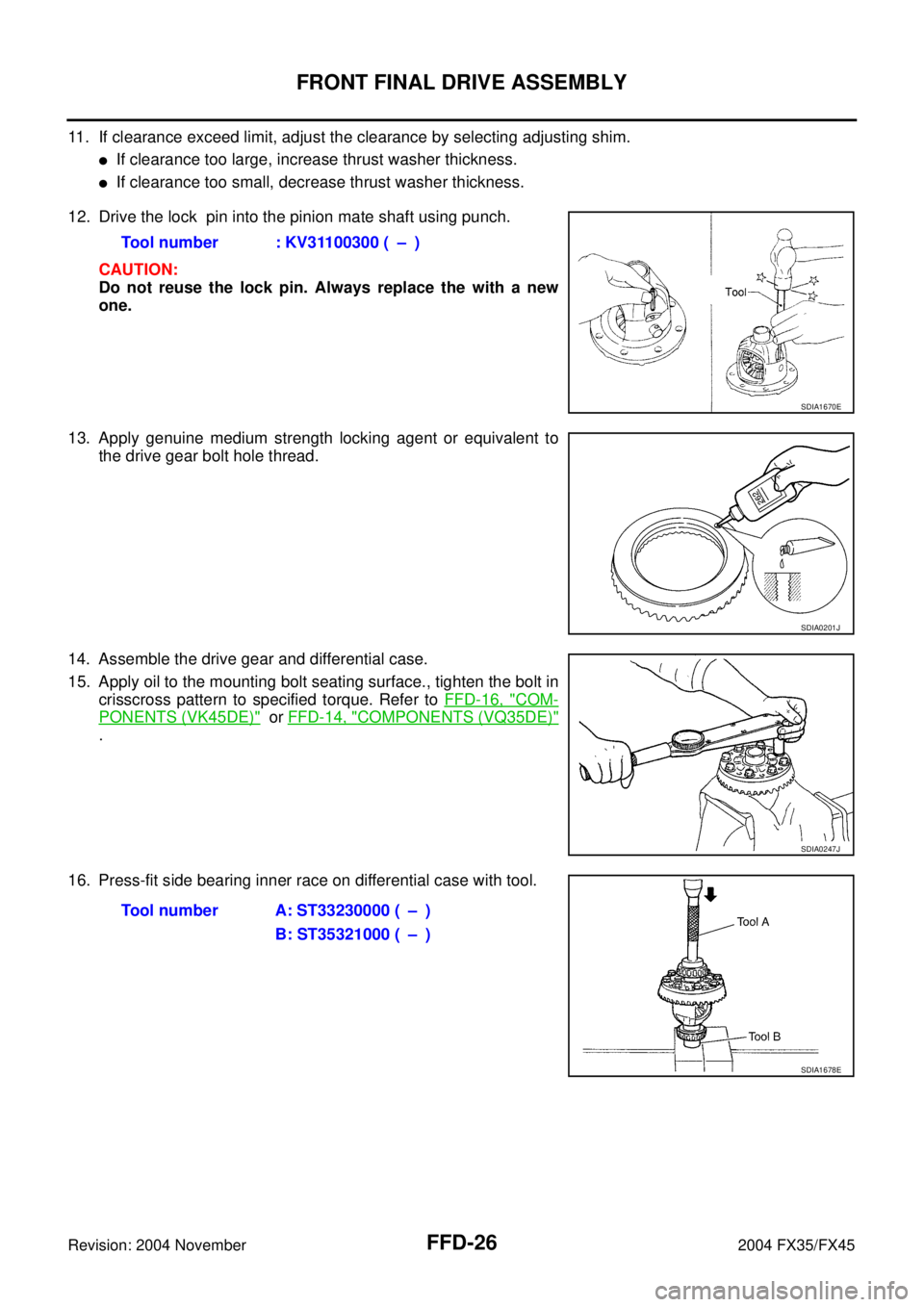
11. If clearance exceed limit, adjust the clearance by selecting adjusting shim.
�If clearance too large, increase thrust washer thickness.
�If clearance too small, decrease thrust washer thickness.
12. Drive the lock pin into the pinion mate shaft using punch.
CAUTION:
Do not reuse the lock pin. Always replace the with a new
one.
13. Apply genuine medium strength locking agent or equivalent to
the drive gear bolt hole thread.
14. Assemble the drive gear and differential case.
15. Apply oil to the mounting bolt seating surface., tighten the bolt in
crisscross pattern to specified torque. Refer to FFD-16, "
COM-
PONENTS (VK45DE)" or FFD-14, "COMPONENTS (VQ35DE)"
.
16. Press-fit side bearing inner race on differential case with tool.Tool number : KV31100300 ( – )
SDIA1670E
SDIA0201J
SDIA0247J
Tool number A: ST33230000 ( – )
B: ST35321000 ( – )
SDIA1678E
Page 3063 of 4449

FFD-28
FRONT FINAL DRIVE ASSEMBLY
Revision: 2004 November 2004 FX35/FX45
CAUTION:
Do not install the drive pinion adjusting washer and drive pinion bearing adjusting washer at this
time.
c. Install the companion flange without installing oil seal.
d. Apply oil drive pinion lock nut threads and seating surface, then temporarily install it.
e. Tighten the drive pinion lock nut until it reach standard preload.
CAUTION:
Tighten the drive pinion nut by very small degrees until the
specified preload in achieved. Do not tighten nut more than
necessary.
DIFFERENTIAL CASE INSTALLATION
1. Drive side bearing outer race into the carrier case with tool.
CAUTION:
Do not apply excessive force to the race.
2. Drive side bearing outer race into the side retainer with tool.
3. Apply oil to the bearing portion.
4. Install the deferential case assembly to the carrier case.
CAUTION:
Be careful not to damage the carrier cover mating surface.
5. Install the side bearing adjusting shim to the side retainer, tighten the bolt to specified torque.
CAUTION:
Install removed adjusting shim or same thickness shim.
NOTE:
Do not install O-ring.Tool number : KV40104000(−)
Pinion bearing preload without oil seal
: 0.78 - 1.57 N·m (0.08 - 0.16 kg-m, 7 - 13 in-lb)
SDIA1669E
Tool number : KV31103000 ( – )
SDIA1680E
Tool number : KV31103000 ( – )
SDIA1679E
![INFINITI FX35 2004 Service Manual SERVICE DATA
FAX-25
[AWD]
C
E
F
G
H
I
J
K
L
MA
B
FA X
Revision: 2004 November 2004 FX35/FX45
SERVICE DATAPFP:00030
Wheel BearingADS000OR
Drive ShaftADS000OS
Tightening TorqueADS000OT
Axial end play 0.](/manual-img/42/57021/w960_57021-3033.png "INFINITI FX35 2004 Service Manual SERVICE DATA
FAX-25
[AWD]
C
E
F
G
H
I
J
K
L
MA
B
FA X
Revision: 2004 November 2004 FX35/FX45
SERVICE DATAPFP:00030
Wheel BearingADS000OR
Drive ShaftADS000OS
Tightening TorqueADS000OT
Axial end play 0.")

a: 49 mm (1.93 in) dia.
b: 41 mm (1.61 in) dia.
DriftInstalling")