Page 3922 of 4449
NOISE, VIBRATION AND HARSHNESS (NVH) TROUBLESHOOTING
PR-3
C
E
F
G
H
I
J
K
L
MA
B
PR
Revision: 2004 November 2004 FX35/FX45
NOISE, VIBRATION AND HARSHNESS (NVH) TROUBLESHOOTINGPFP:00003
NVH Troubleshooting ChartADS000KD
Use the chart below to help you find the cause of the symptom. If necessary, repair or replace these parts.
×: ApplicableReference page
—
Refer to PR-10
for details.
—
Refer to PR-6 for details.
—
NVH in FFD and RFD section
NVH in FAX, RAX, FSU, and RSU section
NVH in WT section
NVH in WT section
NVH in RAX section
NVH in BR section
NVH in PS section
Possible cause and suspected parts
Uneven rotation torque
Center bearing improper installation
Excessive joint angle
Rotation imbalance
Excessive runout
Differential
Axle and suspension
Tires
Road wheel
Drive shaft
Brakes
Ste ering
SymptomNoise××××××××××××
Shake×× ××××××
Vibration××××× ×× × ×
Page 3924 of 4449
FRONT PROPELLER SHAFT
PR-5
C
E
F
G
H
I
J
K
L
MA
B
PR
Revision: 2004 November 2004 FX35/FX45
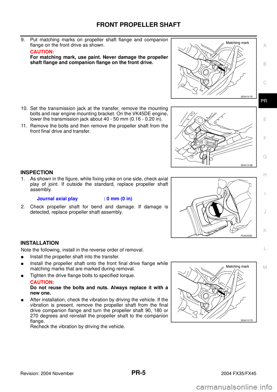
9. Put matching marks on propeller shaft flange and companion
flange on the front drive as shown.
CAUTION:
For matching mark, use paint. Never damage the propeller
shaft flange and companion flange on the front drive.
10. Set the transmission jack at the transfer, remove the mounting
bolts and rear engine mounting bracket. On the VK45DE engine,
lower the transmission jack about 40 - 50 mm (0.16 - 0.20 in).
11. Remove the bolts and then remove the propeller shaft from the
front final drive and transfer.
INSPECTION
1. As shown in the figure, while fixing yoke on one side, check axial
play of joint. If outside the standard, replace propeller shaft
assembly.
2. Check propeller shaft for bend and damage. If damage is
detected, replace propeller shaft assembly.
INSTALLATION
Note the following, install in the reverse order of removal.
�Install the propeller shaft into the transfer.
�Install the propeller shaft onto the front final drive flange while
matching marks that are marked during removal.
�Tighten the drive flange bolts to specified torque.
CAUTION:
Do not reuse the bolts and nuts. Always replace it with a
new one.
�After installation, check the vibration by driving the vehicle. If the
vibration is present, remove the propeller shaft from the final
drive companion flange and turn the propeller shaft 90, 180 or
270 degrees and reinstall the propeller shaft to the companion
flange.
Recheck the vibration by driving the vehicle.
SDIA1517E
SDIA1518E
Journal axial play : 0 mm (0 in)
PDA0005D
SDIA1517E
Page 3929 of 4449
PR-10
REAR PROPELLER SHAFT
Revision: 2004 November 2004 FX35/FX45
INSTALLATION
1. Paying attention to following items, install in the reverse order of removal.
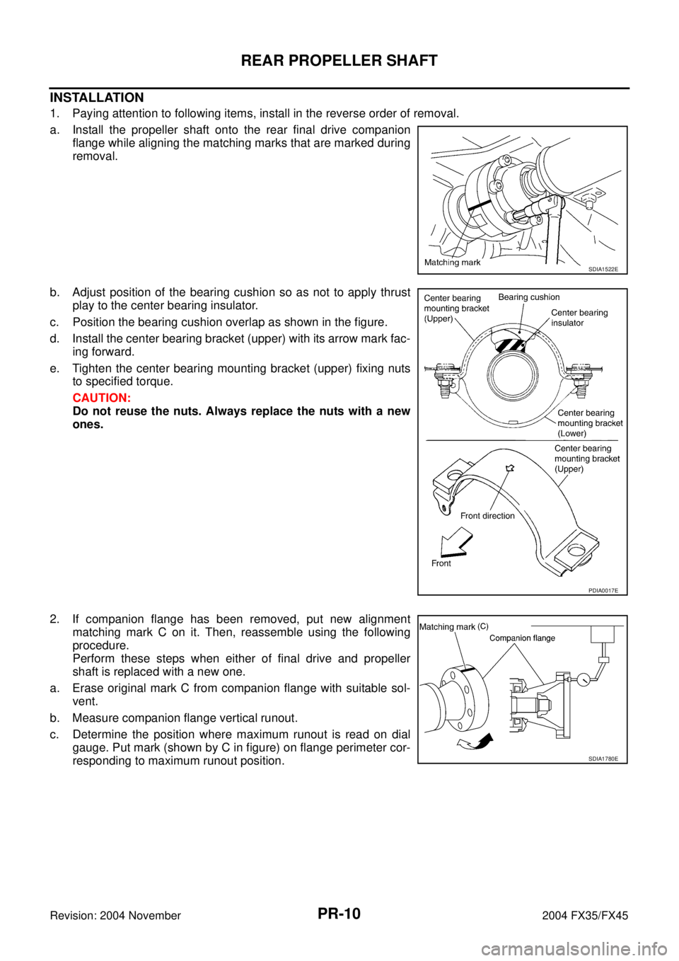
a. Install the propeller shaft onto the rear final drive companion
flange while aligning the matching marks that are marked during
removal.
b. Adjust position of the bearing cushion so as not to apply thrust
play to the center bearing insulator.
c. Position the bearing cushion overlap as shown in the figure.
d. Install the center bearing bracket (upper) with its arrow mark fac-
ing forward.
e. Tighten the center bearing mounting bracket (upper) fixing nuts
to specified torque.
CAUTION:
Do not reuse the nuts. Always replace the nuts with a new
ones.
2. If companion flange has been removed, put new alignment
matching mark C on it. Then, reassemble using the following
procedure.
Perform these steps when either of final drive and propeller
shaft is replaced with a new one.
a. Erase original mark C from companion flange with suitable sol-
vent.
b. Measure companion flange vertical runout.
c. Determine the position where maximum runout is read on dial
gauge. Put mark (shown by C in figure) on flange perimeter cor-
responding to maximum runout position.
SDIA1522E
PDIA0017E
SDIA1780E
Page 3930 of 4449
REAR PROPELLER SHAFT
PR-11
C
E
F
G
H
I
J
K
L
MA
B
PR
Revision: 2004 November 2004 FX35/FX45
3. If the propeller shaft or final drive has been replaced, connect
the propeller shaft and final drive as follows:
NOTE:
Avoid damaging the rebro joint boot, protect it with a shop towel
or equivalent.
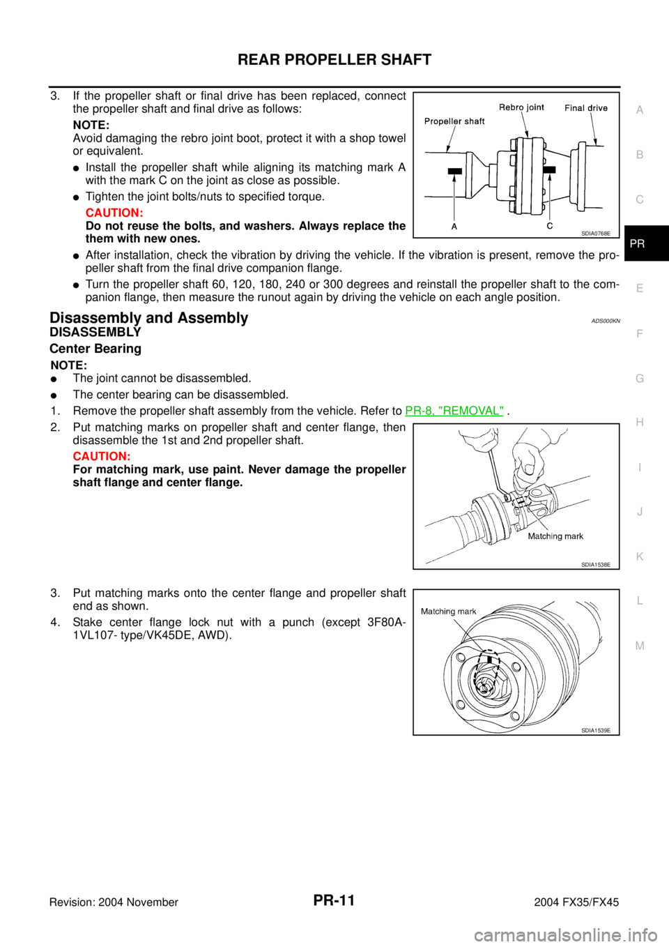
�Install the propeller shaft while aligning its matching mark A
with the mark C on the joint as close as possible.
�Tighten the joint bolts/nuts to specified torque.
CAUTION:
Do not reuse the bolts, and washers. Always replace the
them with new ones.
�After installation, check the vibration by driving the vehicle. If the vibration is present, remove the pro-
peller shaft from the final drive companion flange.
�Turn the propeller shaft 60, 120, 180, 240 or 300 degrees and reinstall the propeller shaft to the com-
panion flange, then measure the runout again by driving the vehicle on each angle position.
Disassembly and AssemblyADS000KN
DISASSEMBLY
Center Bearing
NOTE:
�The joint cannot be disassembled.
�The center bearing can be disassembled.
1. Remove the propeller shaft assembly from the vehicle. Refer to PR-8, "
REMOVAL" .
2. Put matching marks on propeller shaft and center flange, then
disassemble the 1st and 2nd propeller shaft.
CAUTION:
For matching mark, use paint. Never damage the propeller
shaft flange and center flange.
3. Put matching marks onto the center flange and propeller shaft
end as shown.
4. Stake center flange lock nut with a punch (except 3F80A-
1VL107- type/VK45DE, AWD).
SDIA0768E
SDIA1538E
SDIA1539E
Page 3931 of 4449
PR-12
REAR PROPELLER SHAFT
Revision: 2004 November 2004 FX35/FX45
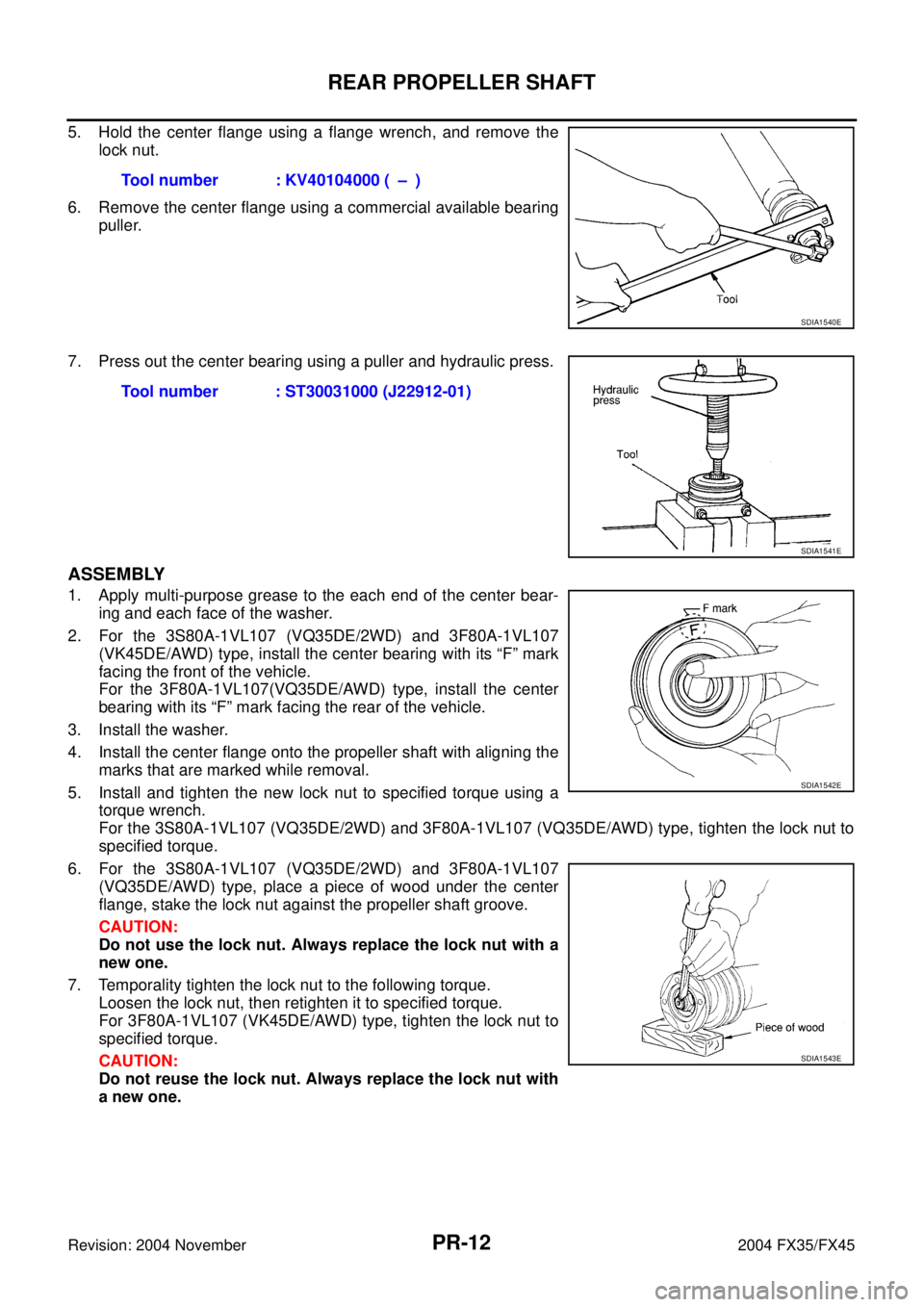
5. Hold the center flange using a flange wrench, and remove the
lock nut.
6. Remove the center flange using a commercial available bearing
puller.
7. Press out the center bearing using a puller and hydraulic press.
ASSEMBLY
1. Apply multi-purpose grease to the each end of the center bear-
ing and each face of the washer.
2. For the 3S80A-1VL107 (VQ35DE/2WD) and 3F80A-1VL107
(VK45DE/AWD) type, install the center bearing with its “F” mark
facing the front of the vehicle.
For the 3F80A-1VL107(VQ35DE/AWD) type, install the center
bearing with its “F” mark facing the rear of the vehicle.
3. Install the washer.
4. Install the center flange onto the propeller shaft with aligning the
marks that are marked while removal.
5. Install and tighten the new lock nut to specified torque using a
torque wrench.
For the 3S80A-1VL107 (VQ35DE/2WD) and 3F80A-1VL107 (VQ35DE/AWD) type, tighten the lock nut to
specified torque.
6. For the 3S80A-1VL107 (VQ35DE/2WD) and 3F80A-1VL107
(VQ35DE/AWD) type, place a piece of wood under the center
flange, stake the lock nut against the propeller shaft groove.
CAUTION:
Do not use the lock nut. Always replace the lock nut with a
new one.
7. Temporality tighten the lock nut to the following torque.
Loosen the lock nut, then retighten it to specified torque.
For 3F80A-1VL107 (VK45DE/AWD) type, tighten the lock nut to
specified torque.
CAUTION:
Do not reuse the lock nut. Always replace the lock nut with
a new one.Tool number : KV40104000 ( – )
SDIA1540E
Tool number : ST30031000 (J22912-01)
SDIA1541E
SDIA1542E
SDIA1543E
Page 3932 of 4449
REAR PROPELLER SHAFT
PR-13
C
E
F
G
H
I
J
K
L
MA
B
PR
Revision: 2004 November 2004 FX35/FX45
8. Assemble the 1st and 2nd shaft propeller shafts while aligning
the matching marks that are marked during removal.
9. Install and tighten the bolts/nuts and tighten them to specified
torque.
CAUTION:
Do not reuse the bolts, nuts and washers. Always replace
the them with new ones.
10. Recheck the tightening torque using a torque wrench.
11. Install the propeller shaft assembly. Refer to PR-10, "
INSTALLA-
TION" .SDIA1538E
Page 3938 of 4449
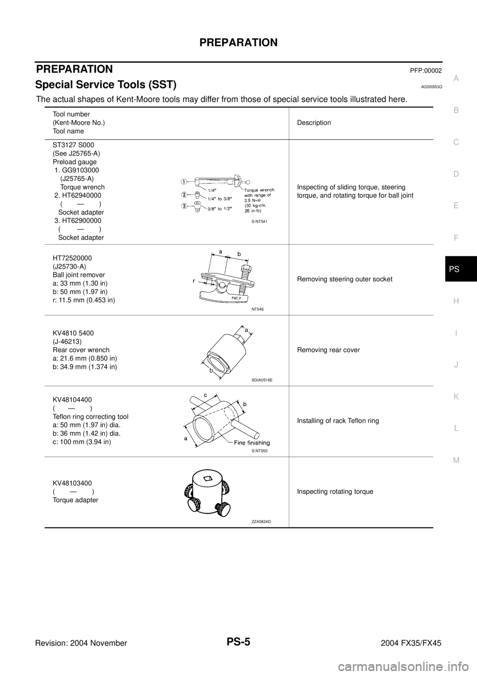
PREPARATION
PS-5
C
D
E
F
H
I
J
K
L
MA
B
PS
Revision: 2004 November 2004 FX35/FX45
PREPARATIONPFP:00002
Special Service Tools (SST)AGS000GQ
The actual shapes of Kent-Moore tools may differ from those of special service tools illustrated here.
Tool number
(Kent-Moore No.)
Tool nameDescription
ST3127 S000
(See J25765-A)
Preload gauge
1. GG9103000
(J25765-A)
Torque wrench
2. HT62940000
( — )
Socket adapter
3. HT62900000
( — )
Socket adapterInspecting of sliding torque, steering
torque, and rotating torque for ball joint
HT72520000
(J25730-A)
Ball joint remover
a: 33 mm (1.30 in)
b: 50 mm (1.97 in)
r: 11.5 mm (0.453 in)Removing steering outer socket
KV4810 5400
(J-46213)
Rear cover wrench
a: 21.6 mm (0.850 in)
b: 34.9 mm (1.374 in)Removing rear cover
KV48104400
( — )
Teflon ring correcting tool
a: 50 mm (1.97 in) dia.
b: 36 mm (1.42 in) dia.
c: 100 mm (3.94 in)Installing of rack Teflon ring
KV48103400
( — )
Torque adapterInspecting rotating torque
S-NT541
NT546
SGIA0516E
S-NT550
ZZA0824D
Page 3940 of 4449
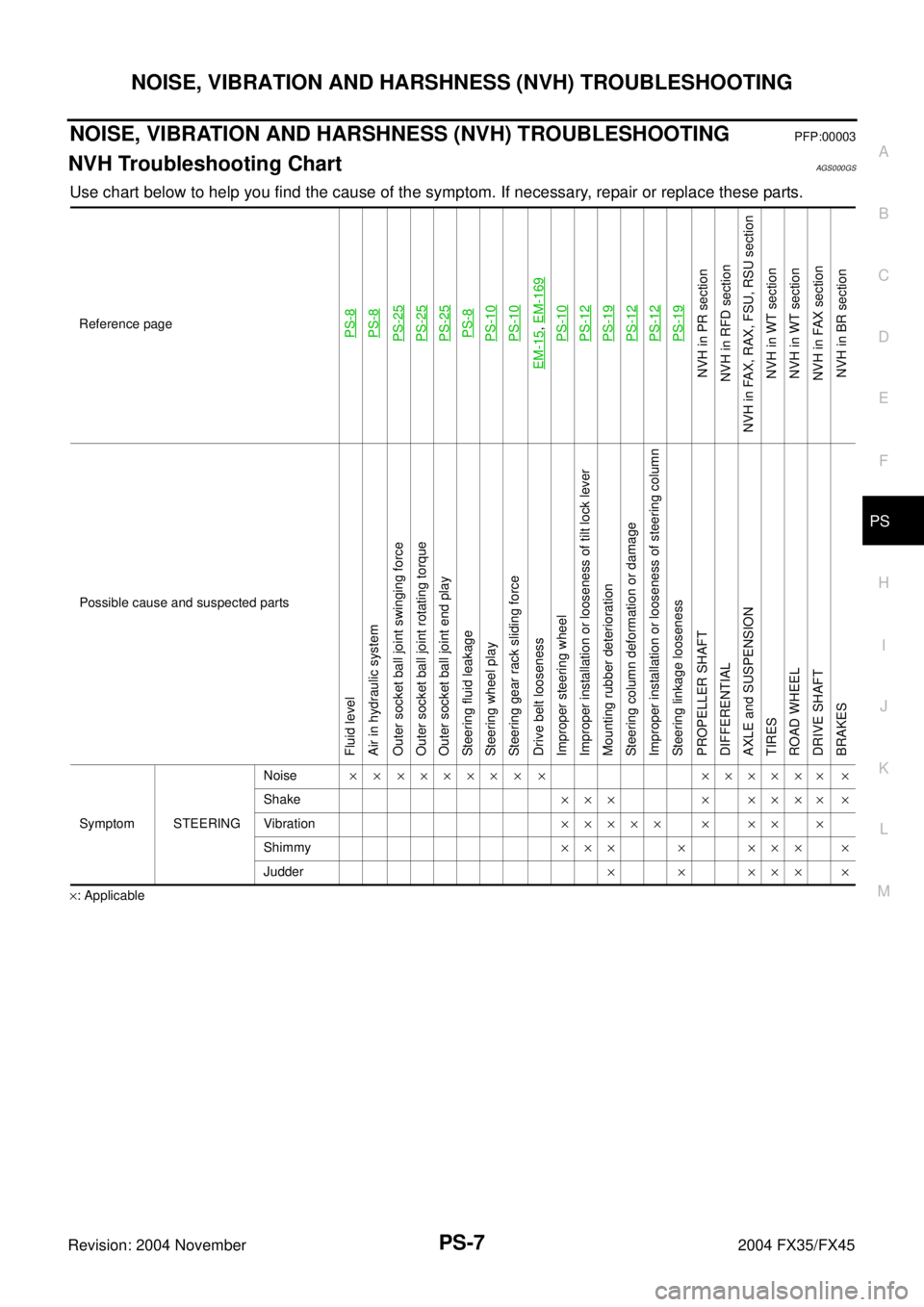
NOISE, VIBRATION AND HARSHNESS (NVH) TROUBLESHOOTING
PS-7
C
D
E
F
H
I
J
K
L
MA
B
PS
Revision: 2004 November 2004 FX35/FX45
NOISE, VIBRATION AND HARSHNESS (NVH) TROUBLESHOOTINGPFP:00003
NVH Troubleshooting ChartAGS000GS
Use chart below to help you find the cause of the symptom. If necessary, repair or replace these parts.
×: ApplicableReference page
PS-8PS-8PS-25PS-25PS-25PS-8PS-10PS-10
EM-15
, EM-169PS-10PS-12PS-19PS-12PS-12PS-19
NVH in PR section
NVH in RFD section
NVH in FAX, RAX, FSU, RSU section
NVH in WT section
NVH in WT section
NVH in FAX section
NVH in BR section
Possible cause and suspected parts
Fluid level
Air in hydraulic system
Outer socket ball joint swinging force
Outer socket ball joint rotating torque
Outer socket ball joint end play
Steering fluid leakage
Steering wheel play
Steering gear rack sliding force
Drive belt looseness
Improper steering wheel
Improper installation or looseness of tilt lock lever
Mounting rubber deterioration
Steering column deformation or damage
Improper installation or looseness of steering column
Steering linkage looseness
PROPELLER SHAFT
DIFFERENTIAL
AXLE and SUSPENSION
TIRES
ROAD WHEEL
DRIVE SHAFT
BRAKES
Symptom STEERINGNoise× × ××××× × × ×××××× ×
Shake××× × ×××× ×
Vibration××××× × ×× ×
Shimmy××× × ××× ×
Judder××××××