Page 2797 of 4449
EM-72
[VQ35DE]
TIMING CHAIN
Revision: 2004 November 2004 FX35/FX45
1. Install timing chain tensioners (secondary) to cylinder head as the following if removed. Refer to EM-87,
"INSTALLATION" .
a. Install chain tensioners with stopper pin attached and new O-rings.
b. Install No. 1 camshaft brackets. Refer to EM-87, "
INSTALLATION" .
2. Install new O-rings onto cylinder block.
3. Install new O-rings to cylinder head.
4. Apply liquid gasket to rear timing chain case back side as shown with tube presser [SST: WS39930000 ( –
)].
Use Genuine RTV Silicone Sealant or equivalent. Refer to GI-48, "
RECOMMENDED CHEMICAL
PRODUCTS AND SEALANTS".
CAUTION:
�For “A” in the figure, completely wipe out liquid gasket extended on a portion touching at
engine coolant.
PBIC0788E
SBIA0496E
Page 2801 of 4449
EM-76
[VQ35DE]
TIMING CHAIN
Revision: 2004 November 2004 FX35/FX45
10. Pull stopper pins out from timing chain tensioners (secondary).
11. Install primary timing chain as follows:
a. Install crankshaft sprocket.
�Make sure the mating marks on crankshaft sprocket face the
front of engine.
b. Install primary timing chain.
�Install primary timing chain so the mating mark (punched) on
camshaft sprocket is aligned with the yellow link on timing
chain, while the mating mark (notched) on crankshaft
sprocket is aligned with the orange one on timing chain, as
shown.
�When it is difficult to align mating marks of primary timing
chain with each sprocket, gradually turn camshaft using a
wrench on the hexagonal portion to align it with the mating
marks.
�During alignment, be careful to prevent dislocation of mating
mark alignments of secondary timing chains.
SEM923G
SEM929E
PBIC1132E
Page 2803 of 4449
EM-78
[VQ35DE]
TIMING CHAIN
Revision: 2004 November 2004 FX35/FX45
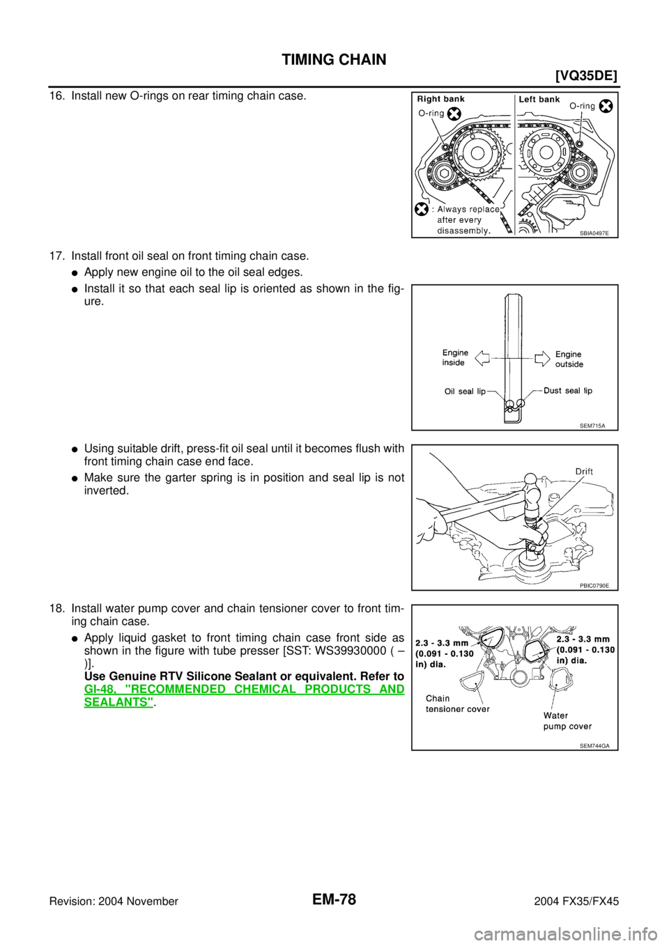
16. Install new O-rings on rear timing chain case.
17. Install front oil seal on front timing chain case.
�Apply new engine oil to the oil seal edges.
�Install it so that each seal lip is oriented as shown in the fig-
ure.
�Using suitable drift, press-fit oil seal until it becomes flush with
front timing chain case end face.
�Make sure the garter spring is in position and seal lip is not
inverted.
18. Install water pump cover and chain tensioner cover to front tim-
ing chain case.
�Apply liquid gasket to front timing chain case front side as
shown in the figure with tube presser [SST: WS39930000 ( –
)].
Use Genuine RTV Silicone Sealant or equivalent. Refer to
GI-48, "
RECOMMENDED CHEMICAL PRODUCTS AND
SEALANTS".
SBIA0497E
SEM715A
PBIC0790E
SEM744GA
Page 2805 of 4449
![INFINITI FX35 2004 Service Manual EM-80
[VQ35DE]
TIMING CHAIN
Revision: 2004 November 2004 FX35/FX45
c. Install collared O-ring in front cover engine oil hole (left and right
sides).
d. Being careful not to move seal ring from the ins](/manual-img/42/57021/w960_57021-2804.png "INFINITI FX35 2004 Service Manual EM-80
[VQ35DE]
TIMING CHAIN
Revision: 2004 November 2004 FX35/FX45
c. Install collared O-ring in front cover engine oil hole (left and right
sides).
d. Being careful not to move seal ring from the ins")
EM-80
[VQ35DE]
TIMING CHAIN
Revision: 2004 November 2004 FX35/FX45
c. Install collared O-ring in front cover engine oil hole (left and right
sides).
d. Being careful not to move seal ring from the installation groove,
align dowel pins on chain case with the holes to install intake
valve timing control covers.
e. Tighten bolts in the numerical order as shown in the figure.
22. Install crankshaft pulley as follows:
a. Fix crankshaft using ring gear stopper [SST: KV10117700 (J-44716)].
b. Install crankshaft pulley, taking care not to damage front oil seal.
�When press-fitting crankshaft pulley with a plastic hammer, tap on its center portion (not circumfer-
ence).
c. Tighten bolt.
d. Put a paint mark on crankshaft pulley aligning with angle mark
on crankshaft pulley bolt. Then, further retighten bolt by “60”
degrees (equivalent to one graduation).
23. Rotate crankshaft pulley in normal direction (clockwise when viewed from front) to confirm it turns
smoothly.
24. For the following operations, perform steps in the reverse order of removal.
NOTE:
If hydraulic pressure inside chain tensioner drops after removal/installation, slack in guide may generate a
pounding noise during and just after engine start. However, this does not indicate an unusualness. Noise
will stop after hydraulic pressure rises.
INSPECTION AFTER INSTALLATION
�Before starting engine, check the levels of engine coolant, lubrications and working fluid. If less than
required quantity, fill to the specified level.
�Run engine to check for unusual noise and vibration.
PBIC2045E
PBIC0918E
: 44.1 N·m (4.5 kg-m, 33 ft-lb)
SEM751G
Page 2806 of 4449
TIMING CHAIN
EM-81
[VQ35DE]
C
D
E
F
G
H
I
J
K
L
MA
EM
Revision: 2004 November 2004 FX35/FX45
�Warm up engine thoroughly to make sure there is no leakage of engine coolant, engine oil and working
fluid, fuel and exhaust gas.
�Bleed air from passages in pipes and tubes of applicable lines, such as in cooling system.
�After cooling down engine, again check amounts of engine coolant, engine oil and working fluid. Refill to
specified level, if necessary.
Summary of the inspection items:
Item Before starting engine Engine running After engine stopped
Engine coolant Level Leakage Level
Engine oil Level Leakage Level
Working fluid Level Leakage Level
Page 2814 of 4449
![INFINITI FX35 2004 Service Manual CAMSHAFT
EM-89
[VQ35DE]
C
D
E
F
G
H
I
J
K
L
MA
EM
Revision: 2004 November 2004 FX35/FX45
5. Tighten camshaft brackets in the following steps, in numerical
order as shown in the figure.
a. Tighten No.](/manual-img/42/57021/w960_57021-2813.png "INFINITI FX35 2004 Service Manual CAMSHAFT
EM-89
[VQ35DE]
C
D
E
F
G
H
I
J
K
L
MA
EM
Revision: 2004 November 2004 FX35/FX45
5. Tighten camshaft brackets in the following steps, in numerical
order as shown in the figure.
a. Tighten No.")
CAMSHAFT
EM-89
[VQ35DE]
C
D
E
F
G
H
I
J
K
L
MA
EM
Revision: 2004 November 2004 FX35/FX45
5. Tighten camshaft brackets in the following steps, in numerical
order as shown in the figure.
a. Tighten No. 7 to 10, then tighten No. 1 to 6 in order as shown.
b. Tighten all bolts in numerical order as shown.
c. Tighten all bolts in the numerical order as shown.
CAUTION:
After tightening mounting bolts of No. 1 camshaft brackets
(No. 1), be sure to wipe off excessive liquid gasket from the
parts list below.
�Mating surface of rocker cover
�Mating surface of rear timing chain case
6. Measure difference in levels between front end faces of No. 1
camshaft bracket and cylinder head.
�If measurement is outside the specified range, re-install cam-
shaft and camshaft bracket.
7. Inspect and adjust valve clearance. Refer to EM-89, "
Valve Clearance" .
8. Install in the reverse order of removal after this step.
Va l v e C l e a r a n c eABS004XG
INSPECTION
Perform inspection as follows after removal, installation or replace-
ment of camshaft or valve-related parts, or if there is unusual engine
conditions regarding valve clearance.
1. Remove right and left rocker covers with power tool. Refer to EM-51, "
ROCKER COVER" .
2. Measure valve clearance as below:
a. Set No. 1 cylinder at TDC of its compression stroke. : 1.96 N·m (0.20 kg-m, 1 ft-lb)
: 5.88 N·m (0.60 kg-m, 4 ft-lb)
: 10.4 N·m (1.1 kg-m, 8 ft-lb)
PBIC2050E
Standard : –0.14 to 0.14 mm (–0.0055 to 0.0055 in)
EMQ0044D
SEM713A
Page 2817 of 4449
![INFINITI FX35 2004 Service Manual EM-92
[VQ35DE]
CAMSHAFT
Revision: 2004 November 2004 FX35/FX45
d. Rotate crankshaft by 240 degrees clockwise (when viewed from
engine front) to align No. 5 cylinder at TDC of compression
stroke.
�No](/manual-img/42/57021/w960_57021-2816.png "INFINITI FX35 2004 Service Manual EM-92
[VQ35DE]
CAMSHAFT
Revision: 2004 November 2004 FX35/FX45
d. Rotate crankshaft by 240 degrees clockwise (when viewed from
engine front) to align No. 5 cylinder at TDC of compression
stroke.
�No")
EM-92
[VQ35DE]
CAMSHAFT
Revision: 2004 November 2004 FX35/FX45
d. Rotate crankshaft by 240 degrees clockwise (when viewed from
engine front) to align No. 5 cylinder at TDC of compression
stroke.
�No. 5 cylinder at compression TDC
CAUTION:
If inspection was carried out with cold engine, make sure
values with fully warmed up engine are still within speci-
fications.
3. For measurements that are outside the specified range, perform adjustment below.
ADJUSTMENT
�Perform adjustment depending on selected head thickness of valve lifter.
�The specified valve lifter thickness is the dimension at normal temperatures. Ignore dimensional differ-
ences caused by temperature. Use the specifications for hot engine condition to adjust.
1. Remove camshaft. Refer to EM-83, "
REMOVAL" .
2. Remove valve lifters at the locations that are outside the standard.
3. Measure the center thickness of the removed valve lifters with a
micrometer.
4. Use the equation below to calculate valve lifter thickness for replacement.
SEM751G
Measuring position (right bank) No. 1 CYL. No. 3 CYL. No. 5 CYL.
No. 5 cylinder at
TDCEXH×
INT×
Measuring position (left bank) No. 2 CYL. No. 4 CYL. No. 6 CYL.
No. 5 cylinder at
TDCINT×
EXH ×
PBIC2056E
KBIA0057E
Page 2818 of 4449
![INFINITI FX35 2004 Service Manual CAMSHAFT
EM-93
[VQ35DE]
C
D
E
F
G
H
I
J
K
L
MA
EM
Revision: 2004 November 2004 FX35/FX45
�Valve lifter thickness calculation:
Thickness of replacement valve lifter = t1+ (C1 - C2)
t1 = Thickness of re](/manual-img/42/57021/w960_57021-2817.png "INFINITI FX35 2004 Service Manual CAMSHAFT
EM-93
[VQ35DE]
C
D
E
F
G
H
I
J
K
L
MA
EM
Revision: 2004 November 2004 FX35/FX45
�Valve lifter thickness calculation:
Thickness of replacement valve lifter = t1+ (C1 - C2)
t1 = Thickness of re")
CAMSHAFT
EM-93
[VQ35DE]
C
D
E
F
G
H
I
J
K
L
MA
EM
Revision: 2004 November 2004 FX35/FX45
�Valve lifter thickness calculation:
Thickness of replacement valve lifter = t1+ (C1 - C2)
t1 = Thickness of removed valve lifter
C1 = Measured valve clearance
C2= Standard valve clearance:
�Thickness of a new valve lifter can be identified by stamp
marks on the reverse side (inside the cylinder).
Stamp mark 788U or 788R indicates 7.88 mm (0.3102 in) in
thickness.
NOTE:
2 types of stamp marks are used for parallel setting and for
manufacturer identification.
Available thickness of valve lifter: 27 sizes with range 7.88 to 8.40 mm (0.3102 to 0.3307 in) in steps of 0.02
mm (0.0008 in) (when manufactured at factory). Refer to EM-149, "
Available Valve Lifter" .
5. Install selected valve lifter.
6. Install camshaft.
7. Manually turn crankshaft pulley a few turns.
8. Make sure valve clearances for cold engine are within specifications by referring to the specified values.
9. After completing the repair, check valve clearances again with the specifications for warmed engine. Make
sure the values are within specifications.
Valve clearance:
Unit: mm (in)
*: Approximately 80°C (176°F)
Intake : 0.30 mm (0.012 in)*
Exhaust : 0.33 mm (0.013 in)*
*: Approximately 20°C (68°F)
KBIA0119E
Items Cold Hot * (reference data)
Intake 0.26 - 0.34 (0.010 - 0.013) 0.304 - 0.416 (0.012 - 0.016)
Exhaust 0.29 - 0.37 (0.011 - 0.015) 0.308 - 0.432 (0.012 - 0.016)
![INFINITI FX35 2004 Service Manual EM-72
[VQ35DE]
TIMING CHAIN
Revision: 2004 November 2004 FX35/FX45
1. Install timing chain tensioners (secondary) to cylinder head as the following if removed. Refer to EM-87,
"INSTALLATION" .
a. Inst](/manual-img/42/57021/w960_57021-2796.png "INFINITI FX35 2004 Service Manual EM-72
[VQ35DE]
TIMING CHAIN
Revision: 2004 November 2004 FX35/FX45
1. Install timing chain tensioners (secondary) to cylinder head as the following if removed. Refer to EM-87,
\"INSTALLATION\" .
a. Inst")
![INFINITI FX35 2004 Service Manual EM-76
[VQ35DE]
TIMING CHAIN
Revision: 2004 November 2004 FX35/FX45
10. Pull stopper pins out from timing chain tensioners (secondary).
11. Install primary timing chain as follows:
a. Install crankshaf](/manual-img/42/57021/w960_57021-2800.png "INFINITI FX35 2004 Service Manual EM-76
[VQ35DE]
TIMING CHAIN
Revision: 2004 November 2004 FX35/FX45
10. Pull stopper pins out from timing chain tensioners (secondary).
11. Install primary timing chain as follows:
a. Install crankshaf")