Page 2749 of 4449
EM-24
[VQ35DE]
INTAKE MANIFOLD
Revision: 2004 November 2004 FX35/FX45
INTAKE MANIFOLDPFP:14003
Removal and InstallationABS004U3
REMOVAL
1. Release fuel pressure. Refer to EC-51, "FUEL PRESSURE RELEASE" .
2. Remove intake manifold collector (upper and lower). Refer to EM-19, "
INTAKE MANIFOLD COLLECTOR"
.
3. Remove fuel tube and fuel injector assembly. Refer to EM-45, "
FUEL INJECTOR AND FUEL TUBE" .
4. Loosen bolts and nuts in reverse order of illustration to remove
intake manifold with power tool.
5. Remove intake manifold gaskets.
CAUTION:
Cover engine openings to avoid entry of foreign materials.
INSPECTION AFTER REMOVAL
Surface Distortion
�Check the surface distortion of the intake manifold mating sur-
face with straightedge and feeler gauge.
�If it exceeds the limit, replace intake manifold.
1. Harness bracket 2. Intake manifold 3. Gasket
SBIA0487E
PBIC0778E
Limit : 0.1 mm (0.04 in)
PBIC0870E
Page 2751 of 4449
![INFINITI FX35 2004 Service Manual EM-26
[VQ35DE]
EXHAUST MANIFOLD AND THREE WAY CATALYST
Revision: 2004 November 2004 FX35/FX45
EXHAUST MANIFOLD AND THREE WAY CATALYSTPFP:14004
Removal and InstallationABS004U4
REMOVAL
WARNING:
Perform](/manual-img/42/57021/w960_57021-2750.png "INFINITI FX35 2004 Service Manual EM-26
[VQ35DE]
EXHAUST MANIFOLD AND THREE WAY CATALYST
Revision: 2004 November 2004 FX35/FX45
EXHAUST MANIFOLD AND THREE WAY CATALYSTPFP:14004
Removal and InstallationABS004U4
REMOVAL
WARNING:
Perform")
EM-26
[VQ35DE]
EXHAUST MANIFOLD AND THREE WAY CATALYST
Revision: 2004 November 2004 FX35/FX45
EXHAUST MANIFOLD AND THREE WAY CATALYSTPFP:14004
Removal and InstallationABS004U4
REMOVAL
WARNING:
Perform the work when the exhaust and cooling system have completely cooled down.
1. Remove engine cover with power tool. Refer to EM-19, "
INTAKE MANIFOLD COLLECTOR" .
2. Remove air cleaner case and air duct. Refer to EM-17, "
AIR CLEANER AND AIR DUCT" .
3. Remove front and rear engine undercover and front cross bar with power tool.
4. Disconnect heated oxygen sensors 2 (bank 1 and bank 2) harness connectors.
5. Using heated oxygen sensor wrench (SST), remove heated oxy-
gen sensors 2 (bank 1 and bank 2).
CAUTION:
�Be careful not to damage heated oxygen sensor.
�Discard any heated oxygen sensor which has been
dropped from a height of more than 0.5 m (19.7 in) onto a
hard surface such as a concrete floor; replace with a new
sensor.
1. Heated oxygen sensor 2 (bank 1) 2. Three way catalyst (right bank) 3. Gasket
4. heated oxygen sensor 1 (bank 1) 5. Exhaust manifold cover (right bank) 6. Exhaust manifold (right bank)
7. Exhaust manifold (left bank) 8. Exhaust manifold cover (left bank) 9. Three way catalyst (left bank)
10. heated oxygen sensor 1 (bank 2) 11. Heated oxygen sensor 2 (bank 2)
SBIA0583E
KBIA1740E
Page 2752 of 4449
![INFINITI FX35 2004 Service Manual EXHAUST MANIFOLD AND THREE WAY CATALYST
EM-27
[VQ35DE]
C
D
E
F
G
H
I
J
K
L
MA
EM
Revision: 2004 November 2004 FX35/FX45
6. Remove exhaust mounting bracket between right/left catalytic converter and tr](/manual-img/42/57021/w960_57021-2751.png "INFINITI FX35 2004 Service Manual EXHAUST MANIFOLD AND THREE WAY CATALYST
EM-27
[VQ35DE]
C
D
E
F
G
H
I
J
K
L
MA
EM
Revision: 2004 November 2004 FX35/FX45
6. Remove exhaust mounting bracket between right/left catalytic converter and tr")
EXHAUST MANIFOLD AND THREE WAY CATALYST
EM-27
[VQ35DE]
C
D
E
F
G
H
I
J
K
L
MA
EM
Revision: 2004 November 2004 FX35/FX45
6. Remove exhaust mounting bracket between right/left catalytic converter and transmission. Refer to EX-3,
"EXHAUST SYSTEM" .
7. Remove three way catalyst (right and left bank).
8. Disconnect heated oxygen sensor 1 (bank 1 and bank 2) harness connectors and remove harness clip.
9. Using heated oxygen sensor wrench (SST), remove heated oxy-
gen sensor 1 (bank 1 and bank 2).
CAUTION:
�Be careful not to damage heated oxygen sensor.
�Discard any heated oxygen sensor which has been
dropped from a height of more than 0.5 m (19.7 in) onto a
hard surface such as a concrete floor; replace with a new
sensor.
10. Remove water pipes on both right and left side. Refer to CO-28, "
WATER OUTLET AND WATER PIPING"
.
11. Remove exhaust manifold cover (right and left bank).
12. Loosen nuts in the reverse order as shown in the figure to
remove exhaust manifold with power tool.
NOTE:
Disregard the numerical order No. 7 and No. 8 in removal.
13. Remove exhaust manifold gaskets.
CAUTION:
Cover engine openings to avoid entry of foreign materials.
SBIA0575E
PBIC2042E
Page 2755 of 4449
![INFINITI FX35 2004 Service Manual EM-30
[VQ35DE]
OIL PAN AND OIL STRAINER
Revision: 2004 November 2004 FX35/FX45
OIL PAN AND OIL STRAINERP F P : 1111 0
Removal and InstallationABS004U5
2WD MODEL
REMOVAL
CAUTION:
To avoid the danger of](/manual-img/42/57021/w960_57021-2754.png "INFINITI FX35 2004 Service Manual EM-30
[VQ35DE]
OIL PAN AND OIL STRAINER
Revision: 2004 November 2004 FX35/FX45
OIL PAN AND OIL STRAINERP F P : 1111 0
Removal and InstallationABS004U5
2WD MODEL
REMOVAL
CAUTION:
To avoid the danger of")
EM-30
[VQ35DE]
OIL PAN AND OIL STRAINER
Revision: 2004 November 2004 FX35/FX45
OIL PAN AND OIL STRAINERP F P : 1111 0
Removal and InstallationABS004U5
2WD MODEL
REMOVAL
CAUTION:
To avoid the danger of being scalded, never drain engine oil when engine is hot.
NOTE:
To remove oil pan (lower) only, take step 5, then step 20. Removal of step 1, hood assembly (step 2) and step
4 are unnecessary.
1. Remove front tire.
2. Remove hood assembly. Refer to BL-14, "
HOOD" .
3. Remove front and rear engine undercover with power tool.
4. Remove front cross bar with power tool. FSU-6, "
FRONT SUSPENSION ASSEMBLY" .
5. Drain engine oil. Refer to LU-9, "
Changing Engine Oil" .
6. Drain engine coolant. Refer to CO-11, "
Changing Engine Coolant" .
1. Oil pan gasket (rear) 2. Oil pan (upper) 3. O-ring
4. Oil pan gasket (front) 5. Oil filter 6. Connector bolt
7. Oil cooler 8. O-ring 9. Relief valve
10. Oil pressure switch 11. Bracket 12. Oil strainer
13. Drain plug 14. Drain plug washer 15. Oil pan (lower)
16. Rear plate 17. Crankshaft position sensor (POS) 18. Seal rubber
19. Rear cover plate
SBIA0587E
Page 2756 of 4449
![INFINITI FX35 2004 Service Manual OIL PAN AND OIL STRAINER
EM-31
[VQ35DE]
C
D
E
F
G
H
I
J
K
L
MA
EM
Revision: 2004 November 2004 FX35/FX45
CAUTION:
Perform when engine is cold.
7. Remove engine cover with power tool. Refer to EM-19, "](/manual-img/42/57021/w960_57021-2755.png "INFINITI FX35 2004 Service Manual OIL PAN AND OIL STRAINER
EM-31
[VQ35DE]
C
D
E
F
G
H
I
J
K
L
MA
EM
Revision: 2004 November 2004 FX35/FX45
CAUTION:
Perform when engine is cold.
7. Remove engine cover with power tool. Refer to EM-19, \"")
OIL PAN AND OIL STRAINER
EM-31
[VQ35DE]
C
D
E
F
G
H
I
J
K
L
MA
EM
Revision: 2004 November 2004 FX35/FX45
CAUTION:
Perform when engine is cold.
7. Remove engine cover with power tool. Refer to EM-19, "
INTAKE MANIFOLD COLLECTOR" .
8. Remove air hose from air duct to mass air flow sensor side and electric throttle control actuator side.
Refer to EM-17, "
AIR CLEANER AND AIR DUCT" .
9. Removal engine rear lower slinger, and install engine rear slinger to sling engine assembly for positioning.
Refer to EM-8, "
Special Service Tools" .
10. Remove front suspension member. Refer to FSU-17, "
FRONT SUSPENSION MEMBER" .
11. Remove drive belt for alternator and power steering pump and A/C compressor. Refer to EM-15, "
DRIVE
BELTS" .
12. Remove alternator stay. Refer to SC-23, "
CHARGING SYSTEM" .
13. Remove starter motor. Refer to SC-10, "
STARTING SYSTEM" .
14. Remove alternator and power steering pump and A/C compressor idler pulley and bracket assembly.
Refer to EM-15, "
DRIVE BELTS" .
15. Disconnect A/T fluid cooler hoses, and remove oil cooler water pipe mounting bolt. Refer to LU-14, "
OIL
COOLER" .
16. Disconnect A/T fluid cooler tube.
17. Remove crankshaft position sensor (POS).
CAUTION:
�Handle carefully to avoid dropping and shocks.
�Do not disassemble.
�Do not allow metal powder to adhere to magnetic part at sensor tip.
�Do not place sensors in a location where they are exposed to magnetism.
18. Remove oil filter, as necessary. Refer to LU-10, "
OIL FILTER" .
19. Remove oil cooler, as necessary. Refer to LU-14, "
OIL COOLER" .
20. Remove oil pan (lower) as the following:
a. Loosen bolts in reverse order as shown in the figure to remove.
b. Insert seal cutter (SST) between oil pan (upper) and oil pan
(lower).
c. Slide seal cutter by tapping on the side of tool with hammer.
Remove oil pan (lower).
CAUTION:
�Be careful not to damage the mating surface.
�Do not insert flat-bladed screwdriver, this will damage the
mating surface.
21. Remove oil strainer.Slinger bolts:
: 28.0 N·m (2.9 kg-m, 21 ft-lb)
PBIC0782E
SEM960F
Page 2760 of 4449
OIL PAN AND OIL STRAINER
EM-35
[VQ35DE]
C
D
E
F
G
H
I
J
K
L
MA
EM
Revision: 2004 November 2004 FX35/FX45
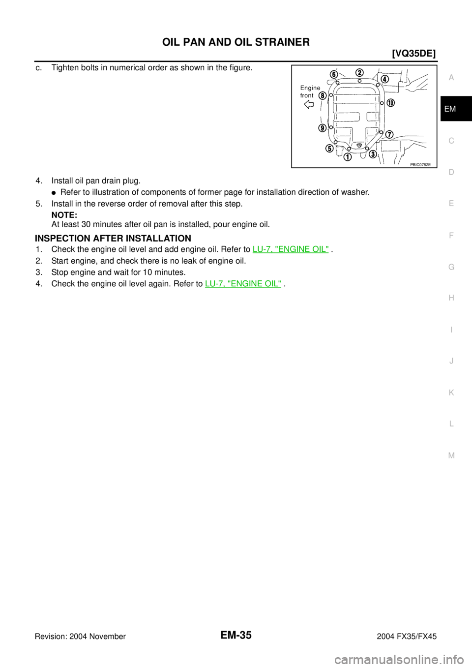
c. Tighten bolts in numerical order as shown in the figure.
4. Install oil pan drain plug.
�Refer to illustration of components of former page for installation direction of washer.
5. Install in the reverse order of removal after this step.
NOTE:
At least 30 minutes after oil pan is installed, pour engine oil.
INSPECTION AFTER INSTALLATION
1. Check the engine oil level and add engine oil. Refer to LU-7, "ENGINE OIL" .
2. Start engine, and check there is no leak of engine oil.
3. Stop engine and wait for 10 minutes.
4. Check the engine oil level again. Refer to LU-7, "
ENGINE OIL" .
PBIC0782E
Page 2761 of 4449
![INFINITI FX35 2004 Service Manual EM-36
[VQ35DE]
OIL PAN AND OIL STRAINER
Revision: 2004 November 2004 FX35/FX45
AW D M OD E L
REMOVAL
CAUTION:
To avoid the danger of being scalded, never drain engine oil when engine is hot.
NOTE:
To](/manual-img/42/57021/w960_57021-2760.png "INFINITI FX35 2004 Service Manual EM-36
[VQ35DE]
OIL PAN AND OIL STRAINER
Revision: 2004 November 2004 FX35/FX45
AW D M OD E L
REMOVAL
CAUTION:
To avoid the danger of being scalded, never drain engine oil when engine is hot.
NOTE:
To")
EM-36
[VQ35DE]
OIL PAN AND OIL STRAINER
Revision: 2004 November 2004 FX35/FX45
AW D M OD E L
REMOVAL
CAUTION:
To avoid the danger of being scalded, never drain engine oil when engine is hot.
NOTE:
To remove oil pan (lower) only, take step 5, then step 24. Removal of step 1, hood assembly (step 2) and step
4 are unnecessary.
1. Remove front tire.
2. Remove hood assembly. Refer to BL-14, "
HOOD" .
3. Remove front and rear engine undercover with power tool.
4. Remove front cross bar with power tool. Refer to FSU-6, "
FRONT SUSPENSION ASSEMBLY" .
5. Drain engine oil. Refer to LU-9, "
Changing Engine Oil" .
6. Drain engine coolant. Refer to CO-11, "
Changing Engine Coolant" .
CAUTION:
Perform when engine is cold.
7. Remove engine cover with power tool. Refer to EM-19, "
INTAKE MANIFOLD COLLECTOR" .
1. Oil pan gasket (rear) 2. Oil pan (upper) 3. O-ring
4. Oil pan gasket (front) 5. Oil filter 6. Connector bolt
7. Oil cooler 8. O-ring 9. Relief valve
10. Oil filter bracket 11. Oil filter bracket gasket 12. Oil strainer
13. Drain plug 14. Drain plug washer 15. Oil pan (lower)
16. Rear plate 17. Crankshaft position sensor (POS) 18 O-ring (small)
19. O-ring (large) 20. Axle pipe
SBIA0567E
Page 2762 of 4449
![INFINITI FX35 2004 Service Manual OIL PAN AND OIL STRAINER
EM-37
[VQ35DE]
C
D
E
F
G
H
I
J
K
L
MA
EM
Revision: 2004 November 2004 FX35/FX45
8. Remove air hose from air duct to mass air flow sensor side and electric throttle control act](/manual-img/42/57021/w960_57021-2761.png "INFINITI FX35 2004 Service Manual OIL PAN AND OIL STRAINER
EM-37
[VQ35DE]
C
D
E
F
G
H
I
J
K
L
MA
EM
Revision: 2004 November 2004 FX35/FX45
8. Remove air hose from air duct to mass air flow sensor side and electric throttle control act")
OIL PAN AND OIL STRAINER
EM-37
[VQ35DE]
C
D
E
F
G
H
I
J
K
L
MA
EM
Revision: 2004 November 2004 FX35/FX45
8. Remove air hose from air duct to mass air flow sensor side and electric throttle control actuator side.
Refer to EM-17, "
AIR CLEANER AND AIR DUCT" .
9. Remove drive belt for alternator and power steering pump and A/C compressor. Refer to EM-15, "
DRIVE
BELTS" .
10. Remove front drive shaft (LH and RH) and side shaft. Refer to FA X - 1 2 , "
FRONT DRIVE SHAFT" .
11. Remove side shaft. Refer to FFD-10, "
FRONT FINAL DRIVE ASSEMBLY" .
12. Removal engine rear lower slinger, and install engine rear slinger to sling engine assembly for positioning.
Refer to EM-8, "
Special Service Tools" .
13. Remove front suspension member. Refer to Refer to FSU-17, "
FRONT SUSPENSION MEMBER" .
14. Remove engine mounting bracket, engine mounting bracket (lower) and insulator. Refer to EM-110,
"ENGINE ASSEMBLY" .
15. Remove front propeller shaft. Refer to PR-4, "
FRONT PROPELLER SHAFT" .
16. Remove oil filter and oil filter bracket. Refer to LU-12, "
OIL FILTER BRACKET (AWD)" .
17. Remove alternator stay. Refer to SC-23, "
CHARGING SYSTEM" .
18. Remove alternator and power steering pump and A/C compressor idler pulley and bracket. Refer to EM-
15, "DRIVE BELTS" .
19. Disconnect A/T fluid cooler hoses, and remove oil cooler water pipe mounting bolt. Refer to LU-14, "
OIL
COOLER" .
20. Disconnect A/T fluid cooler tube.
21. Remove front final drive assembly. Refer to FFD-10, "
FRONT FINAL DRIVE ASSEMBLY" .
22. Remove starter motor. Refer to SC-10, "
STARTING SYSTEM" .
23. Remove crankshaft position sensor (POS).
CAUTION:
�Handle carefully to avoid dropping and shocks.
�Do not disassemble.
�Do not allow metal powder to adhere to magnetic part at sensor tip.
�Do not place sensors in a location where they are exposed to magnetism.
24. Remove oil pan (lower) as the following:
a. Loosen bolts in reverse order as shown in the figure to remove.
b. Insert seal cutter (SST) between oil pan (upper) and oil pan
(lower).
c. Slide seal cutter by tapping on the side of tool with hammer.
Remove oil pan (lower).
CAUTION:
�Be careful not to damage the mating surface.
�Do not insert flat-bladed screwdriver, this will damage the
mating surface.Slinger bolts:
: 28.0 N·m (2.9 kg-m, 21 ft-lb)
PBIC0782E
SEM960F
![INFINITI FX35 2004 Service Manual EM-24
[VQ35DE]
INTAKE MANIFOLD
Revision: 2004 November 2004 FX35/FX45
INTAKE MANIFOLDPFP:14003
Removal and InstallationABS004U3
REMOVAL
1. Release fuel pressure. Refer to EC-51, "FUEL PRESSURE RELEASE](/manual-img/42/57021/w960_57021-2748.png "INFINITI FX35 2004 Service Manual EM-24
[VQ35DE]
INTAKE MANIFOLD
Revision: 2004 November 2004 FX35/FX45
INTAKE MANIFOLDPFP:14003
Removal and InstallationABS004U3
REMOVAL
1. Release fuel pressure. Refer to EC-51, \"FUEL PRESSURE RELEASE")