Page 4344 of 4449

TRANSFER ASSEMBLY
TF-43
C
E
F
G
H
I
J
K
L
MA
B
TF
Revision: 2004 November 2004 FX35/FX45
TRANSFER ASSEMBLYPFP:33100
Removal and InstallationADS000RS
REMOVAL
1. Remove tunnel stay. Refer to RSU-17, "REAR SUSPENSION MEMBER" .
2. Remove exhaust front tube. Refer to EX-3, "
EXHAUST SYSTEM" .
3. Remove front and rear propeller shaft. Refer to PR-4, "
FRONT PROPELLER SHAFT" and PR-6, "REAR
PROPELLER SHAFT" .
4. Disconnect transfer assembly harness connector and separate harness from transfer assembly.
5. Remove air breather hose. Refer to TF-42, "
AIR BREATHER HOSE" .
6. Support transfer assembly with a jack.
7. Remove engine rear mounting. Refer to EM-110, "
ENGINE ASSEMBLY" (VQ35DE) or EM-236, "ENGINE
ASSEMBLY" (VK45DE).
8. Remove transfer mounting bolts and separate transfer from transmission.
CAUTION:
Secure transfer assembly to a jack.
INSTALLATION
Note the following, and install in the reverse order of removal.
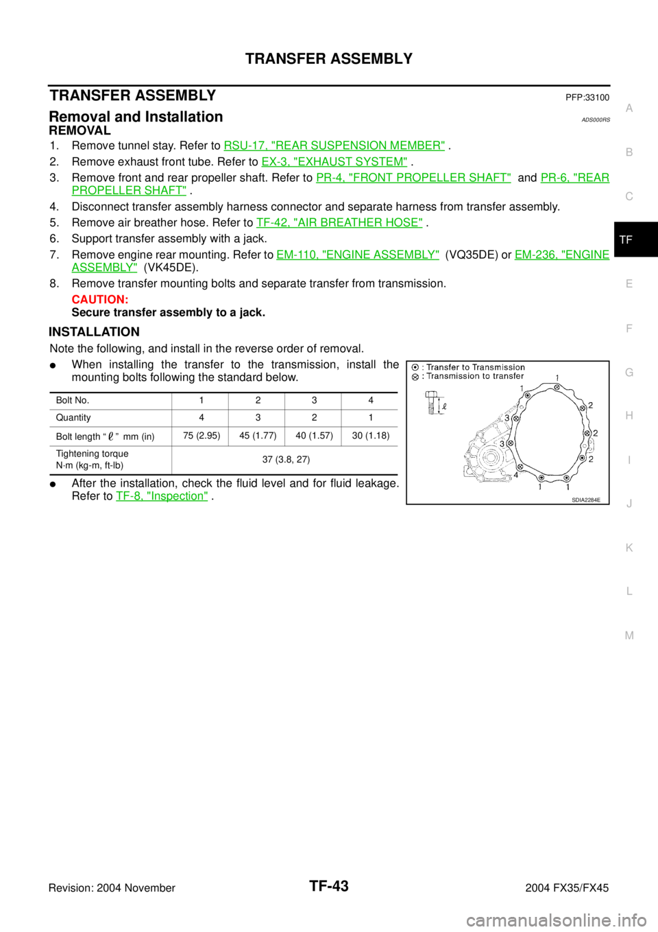
�When installing the transfer to the transmission, install the
mounting bolts following the standard below.
�After the installation, check the fluid level and for fluid leakage.
Refer to TF-8, "
Inspection" .
Bolt No. 1234
Quantity 4 3 2 1
Bolt length “ ” mm (in)75 (2.95) 45 (1.77) 40 (1.57) 30 (1.18)
Tightening torque
N·m (kg-m, ft-lb)37 (3.8, 27)
SDIA2284E
Page 4395 of 4449

WW-4
FRONT WIPER AND WASHER SYSTEM
Revision: 2004 November 2004 FX35/FX45
FRONT WIPER AND WASHER SYSTEMPFP:28810
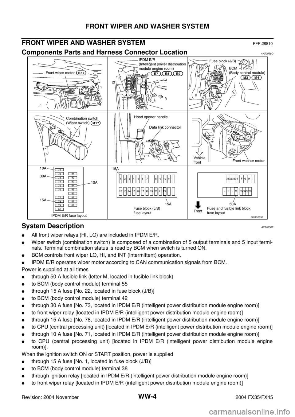
Components Parts and Harness Connector LocationAKS0056O
System DescriptionAKS0056P
�All front wiper relays (HI, LO) are included in IPDM E/R.
�Wiper switch (combination switch) is composed of a combination of 5 output terminals and 5 input termi-
nals. Terminal combination status is read by BCM when switch is turned ON.
�BCM controls front wiper LO, HI, and INT (intermittent) operation.
�IPDM E/R operates wiper motor according to CAN communication signals from BCM.
Power is supplied at all times
�through 50 A fusible link (letter M, located in fusible link block)
�to BCM (body control module) terminal 55
�through 15 A fuse [No. 22, located in fuse block (J/B)]
�to BCM (body control module) terminal 42
�through 30 A fuse [No. 73, located in IPDM E/R (intelligent power distribution module engine room)]
�to front wiper relay [located in IPDM E/R (intelligent power distribution module engine room)]
�through 15 A fuse [No. 78, located in IPDM E/R (intelligent power distribution module engine room)]
�to CPU (central processing unit) [located in IPDM E/R (intelligent power distribution module engine room)]
�through 10 A fuse [No. 71, located in IPDM E/R (intelligent power distribution module engine room)]
�to CPU (central processing unit) [located in IPDM E/R (intelligent power distribution module engine
room)].
When the ignition switch ON or START position, power is supplied
�through 15 A fuse [No. 1, located in fuse block (J/B)]
�to BCM (body control module) terminal 38
�through ignition relay [located in IPDM E/R (intelligent power distribution module engine room)]
�to front wiper relay [located in IPDM E/R (intelligent power distribution module engine room)]
SKIA5289E
Page 4396 of 4449
![INFINITI FX35 2004 Service Manual FRONT WIPER AND WASHER SYSTEM
WW-5
C
D
E
F
G
H
I
J
L
MA
B
WW
Revision: 2004 November 2004 FX35/FX45
�to front wiper high relay [located in IPDM E/R (intelligent power distribution module engine room)] INFINITI FX35 2004 Service Manual FRONT WIPER AND WASHER SYSTEM
WW-5
C
D
E
F
G
H
I
J
L
MA
B
WW
Revision: 2004 November 2004 FX35/FX45
�to front wiper high relay [located in IPDM E/R (intelligent power distribution module engine room)]](/manual-img/42/57021/w960_57021-4395.png)
FRONT WIPER AND WASHER SYSTEM
WW-5
C
D
E
F
G
H
I
J
L
MA
B
WW
Revision: 2004 November 2004 FX35/FX45
�to front wiper high relay [located in IPDM E/R (intelligent power distribution module engine room)]
�through 10 A fuse [No. 84, located in IPDM E/R (intelligent power distribution module engine room)]
�through IPDM E/R (intelligent power distribution module engine room) terminal 44
�to front washer motor terminal 1.
Ground is supplied
�to BCM terminals 49 and 52
�through grounds M35, M45 and M85
�to IPDM E/R terminals 38 and 60
�through grounds E21, E50 and E51
�to combination switch (wiper switch) terminal 12
�through grounds M35, M45 and M85.
LOW SPEED WIPER OPERATION
When wiper switch is in LO position, BCM detects low speed wiper ON signal by BCM wiper switch reading
function.
BCM sends front wiper request signal (LO) with CAN communication line
�from BCM terminals 39 and 40
�to IPDM E/R terminals 48 and 49.
When IPDM E/R receives front wiper request signal (LO), it turns ON front wiper relay (located in IPDM E/R),
power is supplied
�to front wiper motor terminal 1
�through IPDM E/R terminal 21 and front wiper relay and front wiper HI relay.
Ground is supplied
�to front wiper motor terminal 2
�through grounds E21, E50 and E51.
With power and ground supplied, the front wiper motor operates at low speed.
HI SPEED WIPER OPERATION
When wiper switch is in HI position, BCM detects high speed wiper ON signal by BCM wiper switch reading
function.
BCM sends front wiper request signal (HI) with CAN communication line
�from BCM terminals 39 and 40
�to IPDM E/R terminals 48 and 49.
When IPDM E/R receives front wiper request signal (HI), it turns ON front wiper relay (located in IPDM E/R),
power is supplied
�to front wiper motor terminal 4
�through IPDM E/R terminal 31 and front wiper relay and front wiper HI relay.
Ground is supplied
�to front wiper motor terminal 2
�through grounds E21, E50 and E51.
With power and ground supplied, the front wiper motor operates at high speed.
INTERMITTENT OPERATION
Wiper intermittent operation delay interval is determined from a combination of 3 switches (intermittent opera-
tion dial position 1, intermittent operation dial position 2, and intermittent operation dial position 3) and vehicle
speed signal.
During each intermittent operation delay interval, BCM sends front wiper request signal to IPDM E/R.
Page 4426 of 4449

REAR WIPER AND WASHER SYSTEM
WW-35
C
D
E
F
G
H
I
J
L
MA
B
WW
Revision: 2004 November 2004 FX35/FX45
REAR WIPER AND WASHER SYSTEMPFP:28710
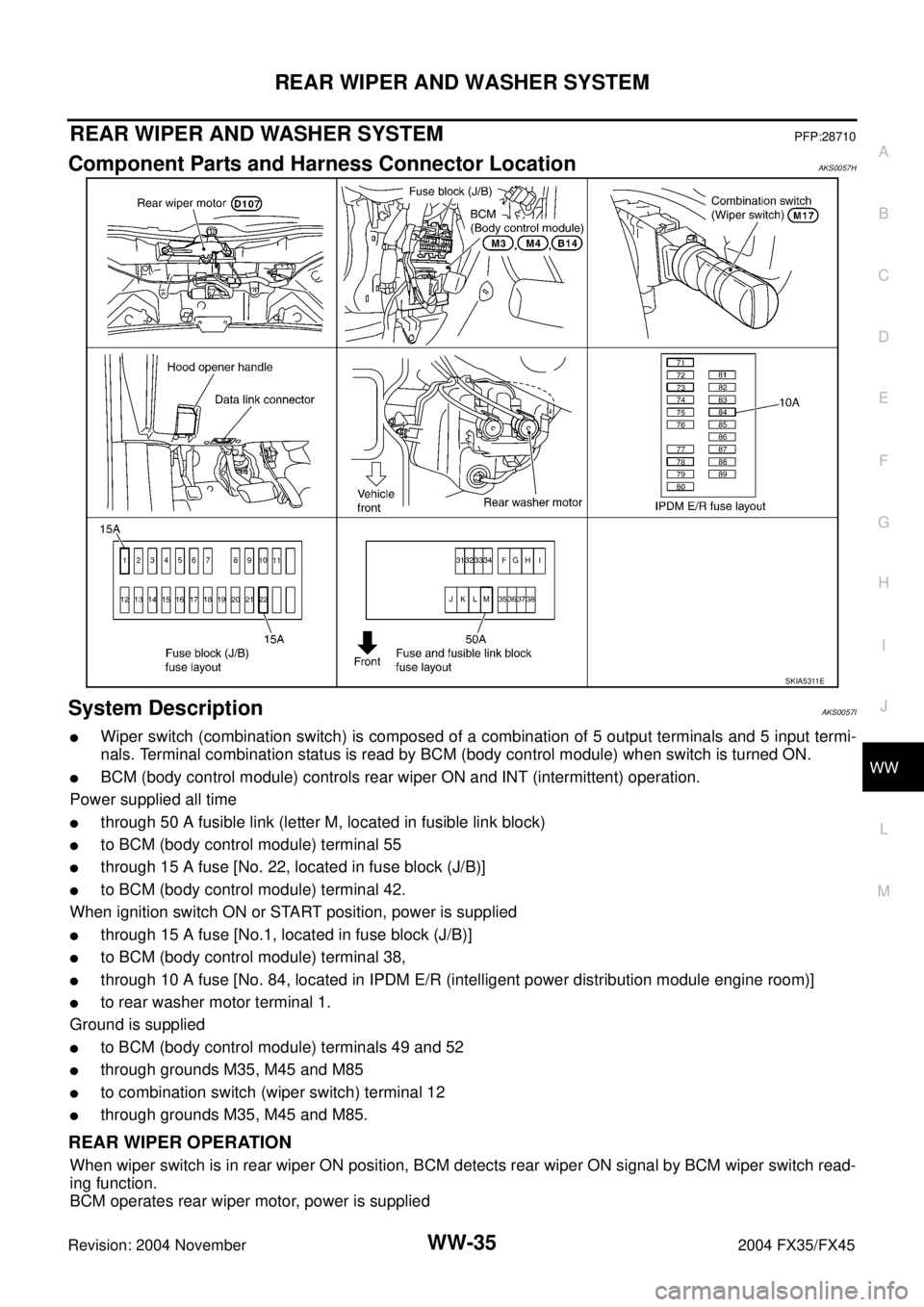
Component Parts and Harness Connector LocationAKS0057H
System DescriptionAKS0057I
�Wiper switch (combination switch) is composed of a combination of 5 output terminals and 5 input termi-
nals. Terminal combination status is read by BCM (body control module) when switch is turned ON.
�BCM (body control module) controls rear wiper ON and INT (intermittent) operation.
Power supplied all time
�through 50 A fusible link (letter M, located in fusible link block)
�to BCM (body control module) terminal 55
�through 15 A fuse [No. 22, located in fuse block (J/B)]
�to BCM (body control module) terminal 42.
When ignition switch ON or START position, power is supplied
�through 15 A fuse [No.1, located in fuse block (J/B)]
�to BCM (body control module) terminal 38,
�through 10 A fuse [No. 84, located in IPDM E/R (intelligent power distribution module engine room)]
�to rear washer motor terminal 1.
Ground is supplied
�to BCM (body control module) terminals 49 and 52
�through grounds M35, M45 and M85
�to combination switch (wiper switch) terminal 12
�through grounds M35, M45 and M85.
REAR WIPER OPERATION
When wiper switch is in rear wiper ON position, BCM detects rear wiper ON signal by BCM wiper switch read-
ing function.
BCM operates rear wiper motor, power is supplied
SKIA5311E