Page 2738 of 4449
NOISE, VIBRATION AND HARSHNESS (NVH) TROUBLESHOOTING
EM-13
[VQ35DE]
C
D
E
F
G
H
I
J
K
L
MA
EM
Revision: 2004 November 2004 FX35/FX45
NOISE, VIBRATION AND HARSHNESS (NVH) TROUBLESHOOTINGPFP:00003
NVH Troubleshooting —Engine NoiseABS004TV
PBIC2039E
Page 2739 of 4449
![INFINITI FX35 2004 Service Manual EM-14
[VQ35DE]
NOISE, VIBRATION AND HARSHNESS (NVH) TROUBLESHOOTING
Revision: 2004 November 2004 FX35/FX45
Use the Chart Below to Help You Find the Cause of the Symptom.ABS004TW
1. Locate the area whe](/manual-img/42/57021/w960_57021-2738.png "INFINITI FX35 2004 Service Manual EM-14
[VQ35DE]
NOISE, VIBRATION AND HARSHNESS (NVH) TROUBLESHOOTING
Revision: 2004 November 2004 FX35/FX45
Use the Chart Below to Help You Find the Cause of the Symptom.ABS004TW
1. Locate the area whe")
EM-14
[VQ35DE]
NOISE, VIBRATION AND HARSHNESS (NVH) TROUBLESHOOTING
Revision: 2004 November 2004 FX35/FX45
Use the Chart Below to Help You Find the Cause of the Symptom.ABS004TW
1. Locate the area where noise occurs.
2. Confirm the type of noise.
3. Specify the operating condition of engine.
4. Check specified noise source.
If necessary, repair or replace these parts.
A: Closely related B: Related C: Sometimes related —: Not relatedLocation
of noiseType of
noiseOperating condition of engine
Source of
noiseCheck itemRefer-
ence page Before
warm-
upAfter
warm-
upWhen
start-
ingWhen
idlingWhen
racingWhile
driving
Top of
engine
Rocker
cover
Cylinder
headTicking or
clickingCA—AB—Tappet
noiseValve clearanceEM-89
Rattle C A — A B CCamshaft
bearing
noiseCamshaft runout
Camshaft journal oil
clearanceEM-84EM-84
Crank-
shaft pul-
ley
Cylinder
block
(Side of
engine)
Oil panSlap or
knock—A—B B—Piston pin
noisePiston to piston pin oil
clearance
Connecting rod bush-
ing oil clearance (Small
end)EM-136
EM-138
Slap or
rapA——B B APiston
slap noisePiston to cylinder bore
clearance
Piston ring side clear-
ance
Piston ring end gap
Connecting rod bend
and torsionEM-140EM-137
EM-137
EM-138
Knock A B C B B BConnect-
ing rod
bearing
noiseConnecting rod bush-
ing oil clearance (Small
end)
Connecting rod bear-
ing housing diameter
(Big end)EM-138EM-138
Knock A B — A B CMain
bearing
noiseMain bearing oil clear-
ance
Crankshaft runoutEM-143EM-142
Front of
engine
Timing
chain
caseTapping or
tickingAA—BBBTiming
chain and
chain ten-
sioner
noiseTiming chain cracks
and wear
Timing chain tensioner
operationEM-71
Front of
engineSqueak-
ing or fizz-
ingAB—B—CDrive belts
(Sticking
or slip-
ping)Drive belts deflection
EM-15
CreakingABABABDrive belts
(Slipping)Idler pulley bearing
operation
Squall
CreakAB—BABWater
pump
noiseWater pump operationCO-22,
"WATER
PUMP"
Page 2740 of 4449
![INFINITI FX35 2004 Service Manual DRIVE BELTS
EM-15
[VQ35DE]
C
D
E
F
G
H
I
J
K
L
MA
EM
Revision: 2004 November 2004 FX35/FX45
DRIVE BELTSPFP:02117
Checking Drive BeltsABS004TX
WARNING:
Be sure to perform when engine is stopped.
1. Ins](/manual-img/42/57021/w960_57021-2739.png "INFINITI FX35 2004 Service Manual DRIVE BELTS
EM-15
[VQ35DE]
C
D
E
F
G
H
I
J
K
L
MA
EM
Revision: 2004 November 2004 FX35/FX45
DRIVE BELTSPFP:02117
Checking Drive BeltsABS004TX
WARNING:
Be sure to perform when engine is stopped.
1. Ins")
DRIVE BELTS
EM-15
[VQ35DE]
C
D
E
F
G
H
I
J
K
L
MA
EM
Revision: 2004 November 2004 FX35/FX45
DRIVE BELTSPFP:02117
Checking Drive BeltsABS004TX
WARNING:
Be sure to perform when engine is stopped.
1. Inspect belts for cracks, fraying, wear and oil. If necessary,
replace.
2. Inspect drive belt deflection or tension at a point on belt midway
between pulleys.
�Inspection should be done only when engine is cold, or over
30 minutes after engine is stopped.
�Measure belt tension with belt tension gauge (Commercial
Service Tool: BT3373-F or equivalent) at points marked
shown in the figure.
�When measuring deflection, apply 98 N (10 kg, 22 lb) at the
marked point.
�Adjust if belt deflection exceeds the limit or if belt tension is not within specifications.
CAUTION:
�When checking belt deflection or tension immediately after installation, first adjust it to the
specified value. Then, after turning crankshaft two turns or more, re-adjust to the specified
value to avoid variation in deflection between pulleys.
�Tighten idler pulley lock nut by hand and measure deflection or tension without looseness.
Belt Deflection and Tension
*: If belt tension gauge cannot be installed at check points shown, check drive belt tension at different location on belt.
Tension AdjustmentABS004TY
CAUTION:
�When belt is replaced with a new one, adjust it to value for “New belt” to accommodate for insuffi-
cient adaptability with pulley grooves.
�When deflection or tension of belt being used exceeds “Limit”, adjust it to value for “After adjust-
ment of used belt”.
�When checking belt deflection or tension immediately after installation, first adjust it to the speci-
fied value. Then, after turning crankshaft two turns or more, re-adjust to the specified value to
avoid variation in deflection between pulleys.
�When installing belt, make sure that it is correctly engaged with pulley grooves.
�Keep engine oil, working fluid and engine coolant away from belt and pulley grooves.
�Do not twist or bend belt excessively.
KBIA1731J
ItemsDeflection adjustment Unit: mm (in) Tension adjustment* Unit: N (kg, lb)
Used belt
New beltUsed belt
New belt
Limit After adjustment Limit After adjustment
Alternator and
power steering
oil pump belt7 (0.28)4 - 5
(0.16 - 0.20)3.5 - 4.5
(0.138 - 0.177)294 (30, 66)730 - 818
(74.5 - 83.5,
164 - 184)838 - 926
(85.5 - 94.5,
188 - 208)
Air conditioner
compressor belt12 (0.47)9 - 10
(0.35 - 0.39)8 - 9
(0.31 - 0.35)196 (20, 44)348 - 436
(35.5 - 44.5,
78 - 98)470 - 559
( 4 8 - 5 7 ,
106 - 126)
Applied pushing
force98 N (10 kg, 22 lb) —
PortionBelt tightening method for adjustment
Alternator and power steering oil pump belt Adjusting bolt on idler pulley
Air conditioner compressor belt Adjusting bolt on idler pulley
Page 2741 of 4449
![INFINITI FX35 2004 Service Manual EM-16
[VQ35DE]
DRIVE BELTS
Revision: 2004 November 2004 FX35/FX45
ALTERNATOR AND POWER STEERING OIL PUMP BELT
1. Remove front engine undercover with power tool.
2. Loosen idler pulley lock nut (A) and](/manual-img/42/57021/w960_57021-2740.png "INFINITI FX35 2004 Service Manual EM-16
[VQ35DE]
DRIVE BELTS
Revision: 2004 November 2004 FX35/FX45
ALTERNATOR AND POWER STEERING OIL PUMP BELT
1. Remove front engine undercover with power tool.
2. Loosen idler pulley lock nut (A) and")
EM-16
[VQ35DE]
DRIVE BELTS
Revision: 2004 November 2004 FX35/FX45
ALTERNATOR AND POWER STEERING OIL PUMP BELT
1. Remove front engine undercover with power tool.
2. Loosen idler pulley lock nut (A) and adjust tension by turning
adjusting bolt (B).
�For specified belt tension, refer to EM-15, "Checking Drive
Belts" .
3. Tighten nut (A).
AIR CONDITIONER COMPRESSOR BELT
1. Remove front engine undercover with power tool.
2. Loosen idler pulley lock nut (C) and adjust tension by turning adjusting bolt (D).
�For specified belt tension, refer to EM-15, "Checking Drive Belts" .
3. Tighten nut (C).
Removal and InstallationABS004TZ
REMOVAL
1. Remove front engine undercover with power tool.
2. Remove alternator and power steering oil pump belt. Refer to EM-16, "
ALTERNATOR AND POWER
STEERING OIL PUMP BELT" .
3. Remove air conditioner compressor belt. Refer to EM-16, "
AIR CONDITIONER COMPRESSOR BELT" .
CAUTION:
Grease is applied to idler pulley adjusting bolt. Be careful to keep grease away from belt.
INSTALLATION
1. Install belts to pulley in reverse order of removal.
CAUTION:
�Make sure belt is correctly engaged with pulley groove.
�Check for engine oil and engine coolant are not adhered to belt and each pulley grooves.
2. Adjust belt tension. Refer to EM-15, "
Tension Adjustment" .
3. Tighten each adjusting bolt and nut to the specified torque.
4. Make sure that tension of each belt is within the standard. : 34.8 N·m (3.5 kg-m, 26 ft-lb)
SBIA0532E
: 34.8 N·m (3.5 kg-m, 26 ft-lb)
Page 2742 of 4449
![INFINITI FX35 2004 Service Manual AIR CLEANER AND AIR DUCT
EM-17
[VQ35DE]
C
D
E
F
G
H
I
J
K
L
MA
EM
Revision: 2004 November 2004 FX35/FX45
AIR CLEANER AND AIR DUCTPFP:16500
Removal and InstallationABS004U0
REMOVAL
1. Remove engine cov](/manual-img/42/57021/w960_57021-2741.png "INFINITI FX35 2004 Service Manual AIR CLEANER AND AIR DUCT
EM-17
[VQ35DE]
C
D
E
F
G
H
I
J
K
L
MA
EM
Revision: 2004 November 2004 FX35/FX45
AIR CLEANER AND AIR DUCTPFP:16500
Removal and InstallationABS004U0
REMOVAL
1. Remove engine cov")
AIR CLEANER AND AIR DUCT
EM-17
[VQ35DE]
C
D
E
F
G
H
I
J
K
L
MA
EM
Revision: 2004 November 2004 FX35/FX45
AIR CLEANER AND AIR DUCTPFP:16500
Removal and InstallationABS004U0
REMOVAL
1. Remove engine cover with power tool. Refer to EM-19, "INTAKE MANIFOLD COLLECTOR" .
�This work is unnecessary when parts located forward of mass air flow sensor are removed/installed.
2. Remove air duct (inlet).
3. Disconnect mass air flow sensor harness connector.
4. Disconnect PCV hose.
5. Remove air cleaner case/mass air flow sensor assembly and air duct/resonator assembly disconnecting
their joints.
�Add marks as necessary for easier installation.
6. Remove mass air flow sensor from air cleaner case.
CAUTION:
Handle mass air flow sensor with care.
�Do not shock it.
�Do not disassemble it.
�Do not touch its sensor.
7. Remove resonator in fender, lifting left fender protector.
INSTALLATION
Note to the following, and install in the reverse order of removal.
1. Air hose 2. PCV hose 3. Air duct
4. Air hose 5. Power duct 6. Clip
7. Air duct (inlet) 8. Resonator 9. Grommet
10. Air cleaner case 11. Air cleaner filter 12. Air cleaner case
13. O-ring 14. Mass air flow sensor
SBIA0462E
Page 2744 of 4449
INTAKE MANIFOLD COLLECTOR
EM-19
[VQ35DE]
C
D
E
F
G
H
I
J
K
L
MA
EM
Revision: 2004 November 2004 FX35/FX45
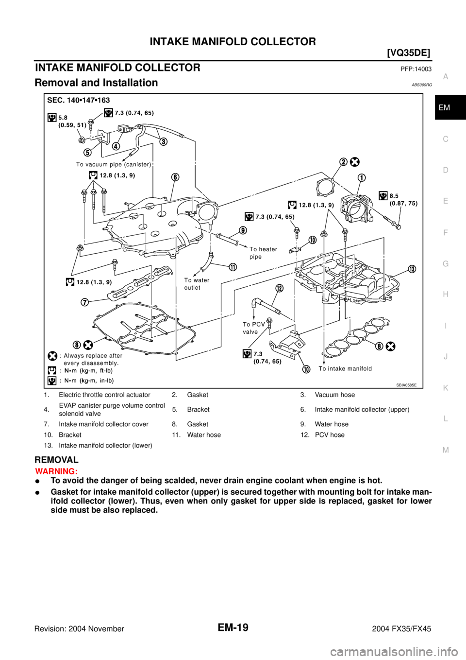
INTAKE MANIFOLD COLLECTORPFP:14003
Removal and InstallationABS009RG
REMOVAL
WARNING:
�To avoid the danger of being scalded, never drain engine coolant when engine is hot.
�Gasket for intake manifold collector (upper) is secured together with mounting bolt for intake man-
ifold collector (lower). Thus, even when only gasket for upper side is replaced, gasket for lower
side must be also replaced.
1. Electric throttle control actuator 2. Gasket 3. Vacuum hose
4.EVAP canister purge volume control
solenoid valve5. Bracket 6. Intake manifold collector (upper)
7. Intake manifold collector cover 8. Gasket 9. Water hose
10. Bracket 11. Water hose 12. PCV hose
13. Intake manifold collector (lower)
SBIA0585E
Page 2745 of 4449
![INFINITI FX35 2004 Service Manual EM-20
[VQ35DE]
INTAKE MANIFOLD COLLECTOR
Revision: 2004 November 2004 FX35/FX45
1. Remove engine cover with power tool.
2. Disconnect water hoses from intake manifold collector (upper), attach blind p](/manual-img/42/57021/w960_57021-2744.png "INFINITI FX35 2004 Service Manual EM-20
[VQ35DE]
INTAKE MANIFOLD COLLECTOR
Revision: 2004 November 2004 FX35/FX45
1. Remove engine cover with power tool.
2. Disconnect water hoses from intake manifold collector (upper), attach blind p")
EM-20
[VQ35DE]
INTAKE MANIFOLD COLLECTOR
Revision: 2004 November 2004 FX35/FX45
1. Remove engine cover with power tool.
2. Disconnect water hoses from intake manifold collector (upper), attach blind plug to prevent engine coolant
leakage.
CAUTION:
�Perform this step when engine is cold.
�Do not spill engine coolant on drive belts.
3. Remove air cleaner case and air duct. Refer to EM-17, "
AIR CLEANER AND AIR DUCT" .
4. Remove electric throttle control actuator as the following:
a. Disconnect harness connector.
b. Loosen bolts in reverse order as shown in the figure.
CAUTION:
�Handle carefully to avoid any shock to electric throttle
control actuator.
�Do not disassemble.
5. Remove fuel sub-tube mounting bolt to disconnect from rear of intake manifold collector (lower). Refer to
EM-45, "
FUEL INJECTOR AND FUEL TUBE" .
6. Disconnect vacuum hose and water hose from intake manifold collector (upper).
7. Remove EVAP canister purge volume control solenoid valve bracket mounting bolt from intake manifold
collector (upper).
SBIA0486E
KBIA0957E
Page 2746 of 4449
INTAKE MANIFOLD COLLECTOR
EM-21
[VQ35DE]
C
D
E
F
G
H
I
J
K
L
MA
EM
Revision: 2004 November 2004 FX35/FX45
8. Loosen bolts in reverse order as shown in the figure to remove
intake manifold collector (upper) with power tool.
9. Remove PCV hose [between intake manifold collector and rocker cover (right bank)].
10. Loosen bolts in reverse order as shown in the figure, and
remove intake manifold collector cover, gasket, intake manifold
collector (lower) and gasket with power tool.
CAUTION:
Cover engine openings to avoid entry of foreign materials.
INSPECTION AFTER REMOVAL
Surface Distortion
�Check the surface distortion of both the intake manifold collector
(upper and lower) mating surfaces with straightedge and feeler
gauge.
�If it exceeds the limit, replace intake manifold collector (upper
and/or lower).
PBIC0773E
PBIC0774E
Limit : 0.1 mm (0.004 in)
PBIC0775E
![INFINITI FX35 2004 Service Manual NOISE, VIBRATION AND HARSHNESS (NVH) TROUBLESHOOTING
EM-13
[VQ35DE]
C
D
E
F
G
H
I
J
K
L
MA
EM
Revision: 2004 November 2004 FX35/FX45
NOISE, VIBRATION AND HARSHNESS (NVH) TROUBLESHOOTINGPFP:00003
NVH T](/manual-img/42/57021/w960_57021-2737.png "INFINITI FX35 2004 Service Manual NOISE, VIBRATION AND HARSHNESS (NVH) TROUBLESHOOTING
EM-13
[VQ35DE]
C
D
E
F
G
H
I
J
K
L
MA
EM
Revision: 2004 November 2004 FX35/FX45
NOISE, VIBRATION AND HARSHNESS (NVH) TROUBLESHOOTINGPFP:00003
NVH T")
![INFINITI FX35 2004 Service Manual INTAKE MANIFOLD COLLECTOR
EM-21
[VQ35DE]
C
D
E
F
G
H
I
J
K
L
MA
EM
Revision: 2004 November 2004 FX35/FX45
8. Loosen bolts in reverse order as shown in the figure to remove
intake manifold collector (u](/manual-img/42/57021/w960_57021-2745.png "INFINITI FX35 2004 Service Manual INTAKE MANIFOLD COLLECTOR
EM-21
[VQ35DE]
C
D
E
F
G
H
I
J
K
L
MA
EM
Revision: 2004 November 2004 FX35/FX45
8. Loosen bolts in reverse order as shown in the figure to remove
intake manifold collector (u")