Page 2744 of 4449
INTAKE MANIFOLD COLLECTOR
EM-19
[VQ35DE]
C
D
E
F
G
H
I
J
K
L
MA
EM
Revision: 2004 November 2004 FX35/FX45
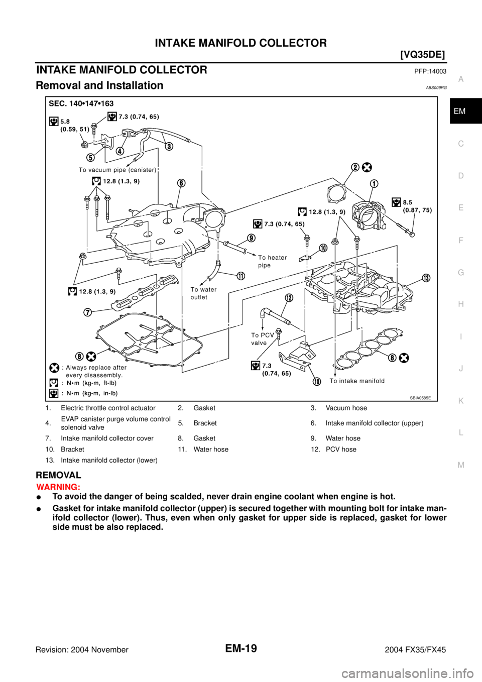
INTAKE MANIFOLD COLLECTORPFP:14003
Removal and InstallationABS009RG
REMOVAL
WARNING:
�To avoid the danger of being scalded, never drain engine coolant when engine is hot.
�Gasket for intake manifold collector (upper) is secured together with mounting bolt for intake man-
ifold collector (lower). Thus, even when only gasket for upper side is replaced, gasket for lower
side must be also replaced.
1. Electric throttle control actuator 2. Gasket 3. Vacuum hose
4.EVAP canister purge volume control
solenoid valve5. Bracket 6. Intake manifold collector (upper)
7. Intake manifold collector cover 8. Gasket 9. Water hose
10. Bracket 11. Water hose 12. PCV hose
13. Intake manifold collector (lower)
SBIA0585E
Page 2745 of 4449
![INFINITI FX35 2004 Service Manual EM-20
[VQ35DE]
INTAKE MANIFOLD COLLECTOR
Revision: 2004 November 2004 FX35/FX45
1. Remove engine cover with power tool.
2. Disconnect water hoses from intake manifold collector (upper), attach blind p](/manual-img/42/57021/w960_57021-2744.png "INFINITI FX35 2004 Service Manual EM-20
[VQ35DE]
INTAKE MANIFOLD COLLECTOR
Revision: 2004 November 2004 FX35/FX45
1. Remove engine cover with power tool.
2. Disconnect water hoses from intake manifold collector (upper), attach blind p")
EM-20
[VQ35DE]
INTAKE MANIFOLD COLLECTOR
Revision: 2004 November 2004 FX35/FX45
1. Remove engine cover with power tool.
2. Disconnect water hoses from intake manifold collector (upper), attach blind plug to prevent engine coolant
leakage.
CAUTION:
�Perform this step when engine is cold.
�Do not spill engine coolant on drive belts.
3. Remove air cleaner case and air duct. Refer to EM-17, "
AIR CLEANER AND AIR DUCT" .
4. Remove electric throttle control actuator as the following:
a. Disconnect harness connector.
b. Loosen bolts in reverse order as shown in the figure.
CAUTION:
�Handle carefully to avoid any shock to electric throttle
control actuator.
�Do not disassemble.
5. Remove fuel sub-tube mounting bolt to disconnect from rear of intake manifold collector (lower). Refer to
EM-45, "
FUEL INJECTOR AND FUEL TUBE" .
6. Disconnect vacuum hose and water hose from intake manifold collector (upper).
7. Remove EVAP canister purge volume control solenoid valve bracket mounting bolt from intake manifold
collector (upper).
SBIA0486E
KBIA0957E
Page 2748 of 4449
INTAKE MANIFOLD COLLECTOR
EM-23
[VQ35DE]
C
D
E
F
G
H
I
J
K
L
MA
EM
Revision: 2004 November 2004 FX35/FX45
�Clamp hose at location of 3 to 7 mm (0.12 to 0.28 in) from hose end.
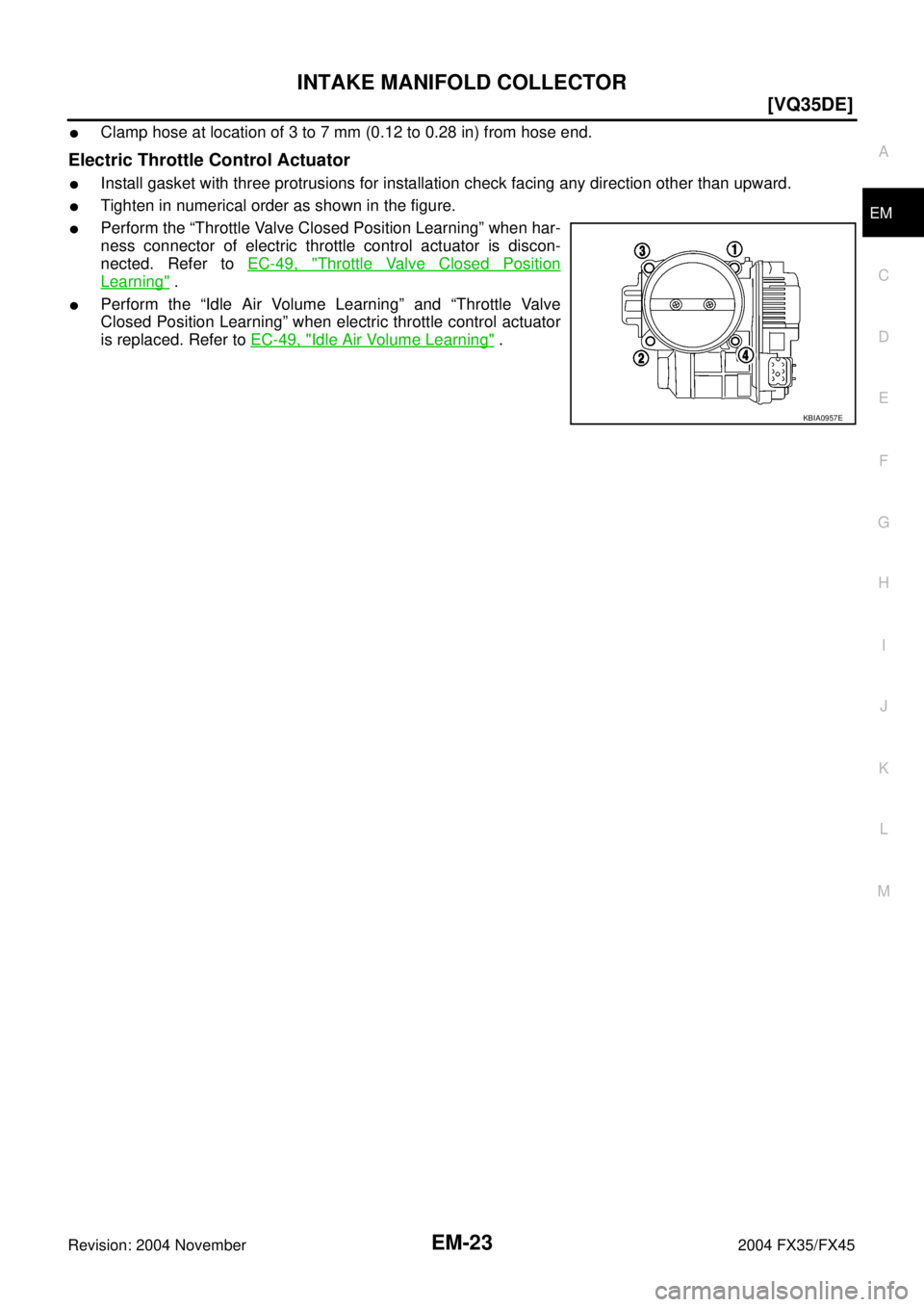
Electric Throttle Control Actuator
�Install gasket with three protrusions for installation check facing any direction other than upward.
�Tighten in numerical order as shown in the figure.
�Perform the “Throttle Valve Closed Position Learning” when har-
ness connector of electric throttle control actuator is discon-
nected. Refer to EC-49, "
Throttle Valve Closed Position
Learning" .
�Perform the “Idle Air Volume Learning” and “Throttle Valve
Closed Position Learning” when electric throttle control actuator
is replaced. Refer to EC-49, "
Idle Air Volume Learning" .
KBIA0957E
Page 2756 of 4449
![INFINITI FX35 2004 Service Manual OIL PAN AND OIL STRAINER
EM-31
[VQ35DE]
C
D
E
F
G
H
I
J
K
L
MA
EM
Revision: 2004 November 2004 FX35/FX45
CAUTION:
Perform when engine is cold.
7. Remove engine cover with power tool. Refer to EM-19, "](/manual-img/42/57021/w960_57021-2755.png "INFINITI FX35 2004 Service Manual OIL PAN AND OIL STRAINER
EM-31
[VQ35DE]
C
D
E
F
G
H
I
J
K
L
MA
EM
Revision: 2004 November 2004 FX35/FX45
CAUTION:
Perform when engine is cold.
7. Remove engine cover with power tool. Refer to EM-19, \"")
OIL PAN AND OIL STRAINER
EM-31
[VQ35DE]
C
D
E
F
G
H
I
J
K
L
MA
EM
Revision: 2004 November 2004 FX35/FX45
CAUTION:
Perform when engine is cold.
7. Remove engine cover with power tool. Refer to EM-19, "
INTAKE MANIFOLD COLLECTOR" .
8. Remove air hose from air duct to mass air flow sensor side and electric throttle control actuator side.
Refer to EM-17, "
AIR CLEANER AND AIR DUCT" .
9. Removal engine rear lower slinger, and install engine rear slinger to sling engine assembly for positioning.
Refer to EM-8, "
Special Service Tools" .
10. Remove front suspension member. Refer to FSU-17, "
FRONT SUSPENSION MEMBER" .
11. Remove drive belt for alternator and power steering pump and A/C compressor. Refer to EM-15, "
DRIVE
BELTS" .
12. Remove alternator stay. Refer to SC-23, "
CHARGING SYSTEM" .
13. Remove starter motor. Refer to SC-10, "
STARTING SYSTEM" .
14. Remove alternator and power steering pump and A/C compressor idler pulley and bracket assembly.
Refer to EM-15, "
DRIVE BELTS" .
15. Disconnect A/T fluid cooler hoses, and remove oil cooler water pipe mounting bolt. Refer to LU-14, "
OIL
COOLER" .
16. Disconnect A/T fluid cooler tube.
17. Remove crankshaft position sensor (POS).
CAUTION:
�Handle carefully to avoid dropping and shocks.
�Do not disassemble.
�Do not allow metal powder to adhere to magnetic part at sensor tip.
�Do not place sensors in a location where they are exposed to magnetism.
18. Remove oil filter, as necessary. Refer to LU-10, "
OIL FILTER" .
19. Remove oil cooler, as necessary. Refer to LU-14, "
OIL COOLER" .
20. Remove oil pan (lower) as the following:
a. Loosen bolts in reverse order as shown in the figure to remove.
b. Insert seal cutter (SST) between oil pan (upper) and oil pan
(lower).
c. Slide seal cutter by tapping on the side of tool with hammer.
Remove oil pan (lower).
CAUTION:
�Be careful not to damage the mating surface.
�Do not insert flat-bladed screwdriver, this will damage the
mating surface.
21. Remove oil strainer.Slinger bolts:
: 28.0 N·m (2.9 kg-m, 21 ft-lb)
PBIC0782E
SEM960F
Page 2762 of 4449
![INFINITI FX35 2004 Service Manual OIL PAN AND OIL STRAINER
EM-37
[VQ35DE]
C
D
E
F
G
H
I
J
K
L
MA
EM
Revision: 2004 November 2004 FX35/FX45
8. Remove air hose from air duct to mass air flow sensor side and electric throttle control act](/manual-img/42/57021/w960_57021-2761.png "INFINITI FX35 2004 Service Manual OIL PAN AND OIL STRAINER
EM-37
[VQ35DE]
C
D
E
F
G
H
I
J
K
L
MA
EM
Revision: 2004 November 2004 FX35/FX45
8. Remove air hose from air duct to mass air flow sensor side and electric throttle control act")
OIL PAN AND OIL STRAINER
EM-37
[VQ35DE]
C
D
E
F
G
H
I
J
K
L
MA
EM
Revision: 2004 November 2004 FX35/FX45
8. Remove air hose from air duct to mass air flow sensor side and electric throttle control actuator side.
Refer to EM-17, "
AIR CLEANER AND AIR DUCT" .
9. Remove drive belt for alternator and power steering pump and A/C compressor. Refer to EM-15, "
DRIVE
BELTS" .
10. Remove front drive shaft (LH and RH) and side shaft. Refer to FA X - 1 2 , "
FRONT DRIVE SHAFT" .
11. Remove side shaft. Refer to FFD-10, "
FRONT FINAL DRIVE ASSEMBLY" .
12. Removal engine rear lower slinger, and install engine rear slinger to sling engine assembly for positioning.
Refer to EM-8, "
Special Service Tools" .
13. Remove front suspension member. Refer to Refer to FSU-17, "
FRONT SUSPENSION MEMBER" .
14. Remove engine mounting bracket, engine mounting bracket (lower) and insulator. Refer to EM-110,
"ENGINE ASSEMBLY" .
15. Remove front propeller shaft. Refer to PR-4, "
FRONT PROPELLER SHAFT" .
16. Remove oil filter and oil filter bracket. Refer to LU-12, "
OIL FILTER BRACKET (AWD)" .
17. Remove alternator stay. Refer to SC-23, "
CHARGING SYSTEM" .
18. Remove alternator and power steering pump and A/C compressor idler pulley and bracket. Refer to EM-
15, "DRIVE BELTS" .
19. Disconnect A/T fluid cooler hoses, and remove oil cooler water pipe mounting bolt. Refer to LU-14, "
OIL
COOLER" .
20. Disconnect A/T fluid cooler tube.
21. Remove front final drive assembly. Refer to FFD-10, "
FRONT FINAL DRIVE ASSEMBLY" .
22. Remove starter motor. Refer to SC-10, "
STARTING SYSTEM" .
23. Remove crankshaft position sensor (POS).
CAUTION:
�Handle carefully to avoid dropping and shocks.
�Do not disassemble.
�Do not allow metal powder to adhere to magnetic part at sensor tip.
�Do not place sensors in a location where they are exposed to magnetism.
24. Remove oil pan (lower) as the following:
a. Loosen bolts in reverse order as shown in the figure to remove.
b. Insert seal cutter (SST) between oil pan (upper) and oil pan
(lower).
c. Slide seal cutter by tapping on the side of tool with hammer.
Remove oil pan (lower).
CAUTION:
�Be careful not to damage the mating surface.
�Do not insert flat-bladed screwdriver, this will damage the
mating surface.Slinger bolts:
: 28.0 N·m (2.9 kg-m, 21 ft-lb)
PBIC0782E
SEM960F
Page 2776 of 4449
ROCKER COVER
EM-51
[VQ35DE]
C
D
E
F
G
H
I
J
K
L
MA
EM
Revision: 2004 November 2004 FX35/FX45
ROCKER COVERPFP:13264
Removal and InstallationABS004U9
REMOVAL
1. Remove intake manifold collectors (upper and lower). Refer to EM-19, "INTAKE MANIFOLD COLLEC-
TOR" .
2. Remove ignition coil. Refer to EM-42, "
IGNITION COIL" .
3. Remove PCV hoses from rocker covers.
4. Remove PCV valve and O-ring from rocker cover (right bank), if necessary.
5. Remove oil filler cap from rocker cover (left bank), if necessary.
1. PCV hose 2. Oil filler cap 3. Oil catcher
4. Rocker cover (right bank) 5. PCV control valve 6. O-ring
7. Rocker cover gasket 8. Rocker cover (left bank)
PBIC2303E
Page 2779 of 4449
![INFINITI FX35 2004 Service Manual EM-54
[VQ35DE]
FRONT TIMING CHAIN CASE
Revision: 2004 November 2004 FX35/FX45
FRONT TIMING CHAIN CASEPFP:13599
Removal and InstallationABS004X0
NOTE:
�This section describes removal/installation proce](/manual-img/42/57021/w960_57021-2778.png "INFINITI FX35 2004 Service Manual EM-54
[VQ35DE]
FRONT TIMING CHAIN CASE
Revision: 2004 November 2004 FX35/FX45
FRONT TIMING CHAIN CASEPFP:13599
Removal and InstallationABS004X0
NOTE:
�This section describes removal/installation proce")
EM-54
[VQ35DE]
FRONT TIMING CHAIN CASE
Revision: 2004 November 2004 FX35/FX45
FRONT TIMING CHAIN CASEPFP:13599
Removal and InstallationABS004X0
NOTE:
�This section describes removal/installation procedure of front timing chain case and timing chain related
parts without removing oil pan (upper) on vehicle.
�When oil pan (upper) needs to be removed or installed, or when rear timing chain case is removed or
installed, remove oil pans (upper and lower) first. Then remove front timing chain case, timing chain
related parts, and rear timing chain case in this order, and install in reverse order of removal. Refer to EM-
63, "TIMING CHAIN" .
�Refer to EM-63, "TIMING CHAIN" for component parts location.
REMOVAL
1. Place vehicle onto lift.
2. Disconnect negative battery terminal.
3. Remove engine cover with power tool. Refer to EM-19, "
INTAKE MANIFOLD COLLECTOR" .
4. Remove air cleaner case assembly. Refer to EM-17, "
AIR CLEANER AND AIR DUCT" .
5. Remove front and rear engine undercover with power tool.
6. Drain engine coolant from radiator. Refer to CO-11, "
Changing Engine Coolant" .
7. Drain engine oil from oil pan. Refer to LU-9, "
Changing Engine Oil" .
8. Remove engine harnesses.
9. Remove intake manifold collectors (upper and lower) with power tool. Refer to EM-19, "
INTAKE MANI-
FOLD COLLECTOR" .
10. Remove power steering oil pump from bracket with piping connected, and temporarily secure it aside.
Refer to PS-31, "
POWER STEERING OIL PUMP" .
11. Remove power steering oil pump bracket. Refer to PS-31, "
POWER STEERING OIL PUMP" .
12. Remove alternator. Refer to SC-23, "
CHARGING SYSTEM" .
13. Remove water bypass hose, water hose clamp and idler pulley bracket and alternator and power steering
oil pump and A/C compressor belt tensioner from front timing chain case.
14. Remove right and left intake valve timing control covers with
power tool.
�Loosen bolts in reverse order as shown in the figure.
�U s e s e a l c u t t e r [ S S T: K V 1 0 1111 0 0 ( J - 3 7 2 2 8 ) ] o r a n e q u i v a l e n t
tool to cut liquid gasket for removal.
CAUTION:
Shaft is internally jointed with intake camshaft sprocket
center hole. When removing, keep it horizontal until it is
completely disconnected.
15. Remove collared O-rings from front timing chain case (left and
right side).
16. Remove right and left rocker covers. Refer to EM-51, "
ROCKER COVER" .
NOTE:
When secondary timing chain is not removed/installed, this step is not required.
SEM728G
PBIC2045E
Page 2786 of 4449
![INFINITI FX35 2004 Service Manual FRONT TIMING CHAIN CASE
EM-61
[VQ35DE]
C
D
E
F
G
H
I
J
K
L
MA
EM
Revision: 2004 November 2004 FX35/FX45
7. Install two mounting bolts in front of oil pan (upper) in numerical
order as shown in the fig](/manual-img/42/57021/w960_57021-2785.png "INFINITI FX35 2004 Service Manual FRONT TIMING CHAIN CASE
EM-61
[VQ35DE]
C
D
E
F
G
H
I
J
K
L
MA
EM
Revision: 2004 November 2004 FX35/FX45
7. Install two mounting bolts in front of oil pan (upper) in numerical
order as shown in the fig")
FRONT TIMING CHAIN CASE
EM-61
[VQ35DE]
C
D
E
F
G
H
I
J
K
L
MA
EM
Revision: 2004 November 2004 FX35/FX45
7. Install two mounting bolts in front of oil pan (upper) in numerical
order as shown in the figure.
8. Install oil pan (lower). Refer to EM-30, "
OIL PAN AND OIL STRAINER" .
9. Install right and left intake valve timing control covers as follows:
a. Install seal rings in shaft grooves.
b. Apply liquid gasket to intake valve timing control covers with
tube presser [SST: WS39930000 ( – )].
Use Genuine RTV Silicone Sealant or equivalent. Refer to
GI-48, "
RECOMMENDED CHEMICAL PRODUCTS AND
SEALANTS".
c. Install collared O-ring in front timing chain case oil hole (left and
right sides).
d. Being careful not to move seal ring from the installation groove,
align dowel pins on chain case with the holes to install intake
valve timing control covers.
e. Tighten bolts in the numerical order as shown in the figure.
10. Install crankshaft pulley as follows:
a. Fix crankshaft using ring gear stopper [SST: KV10117700 (J-44716)].
b. Install crankshaft pulley, taking care not to damage front oil seal.
�When press-fitting crankshaft pulley with a plastic hammer, tap on its center portion (not circumfer-
ence).
c. Tighten bolt. : 17.2 N·m (1.8 kg-m, 13 ft-lb)
PBIC1116E
SBIA0492E
PBIC2045E
: 11.3 N·m (1.2 kg-m, 8 ft-lb)
PBIC0918E
: 44.1 N·m (4.5 kg-m, 33 ft-lb)
![INFINITI FX35 2004 Service Manual ROCKER COVER
EM-51
[VQ35DE]
C
D
E
F
G
H
I
J
K
L
MA
EM
Revision: 2004 November 2004 FX35/FX45
ROCKER COVERPFP:13264
Removal and InstallationABS004U9
REMOVAL
1. Remove intake manifold collectors (upper](/manual-img/42/57021/w960_57021-2775.png "INFINITI FX35 2004 Service Manual ROCKER COVER
EM-51
[VQ35DE]
C
D
E
F
G
H
I
J
K
L
MA
EM
Revision: 2004 November 2004 FX35/FX45
ROCKER COVERPFP:13264
Removal and InstallationABS004U9
REMOVAL
1. Remove intake manifold collectors (upper")