Page 305 of 317

OWNER MAINTENANCE 6-27
DESCRIPTION
H/LP IND
HTD IND
A/CON
RR HTD
STOP
D/LOCK
HAZARD AUDIO
C/LIGHT A/B
A/B IND
T/SIG
ECU
ETACS
RR WPR START
FRT WPR S/HTD
P/OUTLET
IG2
O/S MRR
G200D01FC-GAT
Inner Panel
G200D01FC-D
PROTECTED COMPONENTS Head lamp indicator Defogger relay, Left(Right) outside mirror motor, Rear window motor A/C Switch Defogger relay Stop lamp switch, Power window relay Door lock(unlock) relay, ETACM, Sunroof relay Burglar alarm relay, Hazard relay Audio Cigarette lighter SRS control module SRS IND. Hazard switch, Seat belt timer, Instrument cluster, ABS control module, Pre-excitation resistor, Washer motor ECM, Vehicle speed sensor, TCM, Ignition coil ETACM, A/T Shift lever Rear wiper motor, Rear wiper relay Start relay Wiper relay, Washer motor, Wiper & Defogger timer Left (Right) front seat warmer switch Front (Rear) power outlet ETACM, Power window relay, Defogger relay, Sunroof relay Head lamp relay, Blower relay Outside mirror switch, Rear fog lamp relay
FUSE RATING
10A 10A 10A 30A 10A 15A 10A 10A 15A 10A 10A 10A 15A 10A 10A 10A 20A 15A 25A 10A 10A
fcuk-6.p65 3/6/2007, 10:01 AM
27
Page 306 of 317

EMISSION CONTROL SYSTEM 7-1
SH000A1-E
7. EMISSION
CONTROL SYSTEM
SH010A1-E EMISSION CONTROL SYSTEMS (Not all models) Depending upon the market for which the ve-hicle is destined, the emission control systemwill comprise one or more of the followingemission control devices. (1) Crankcase emission control system (2) Evaporative emission control system (3) Exhaust emission control system In order that the proper functioning of the emis- sion control systems may be ensured, it isrecommended that the vehicle is inspected andmaintained by an authorized Hyundai dealer inaccordance with the maintenance schedule inthis manual. SH010B1-E 1. CRANKCASE EMISSION CONTROL SYSTEM
The positive crankcase ventilation system is employed to prevent air pollution caused byblow-by gases being emitted from the crank-case by introducing fresh air to the crankcase through the air cleaner where this mixes withblow-by gases and then passes through thePCV valve into the intake manifold from whereit subsequently enters the combustion cham-ber and is burned.
SH010D1-E 3. EXHAUST EMISSION CONTROL SYSTEM The exhaust emission control system is a highlyeffective system which controls exhaust emis-sion while maintaining good vehicle perfor-mance.
SH010C1-E
2. EVAPORATIVE EMISSION
CONTROL SYSTEM
The Evaporative Emission Control System is designed to prevent fuel vapours from escap-ing into the atmosphere through the fuel tankventilation system.Whilst the engine is not running, fuel vapoursgenerated inside the fuel tank are absorbedand stored in a charcoal canister. When theengine is started, the vapours stored in thecanister are drawn into the induction systemthrough the purge control solenoid valve andare subsequently burned.The purge control solenoid valve is controlledby the ECU; when the engine coolant tempera-ture is low or the engine is idling, the purgecontrol valve is closed and fuel vapours remainstored in the canister. Under normal runningconditions when the engine is warm, the valveopens and the vapours are drawn into the inlettract and subsequently burned in the combus-tion chamber. SH020A1-E
Catalytic Convertor Operation Precautions; For a gasoline engine Hyundai Matrix models are fitted with catalytic convertors which require special operatingconsiderations. The catalytic convertor servesto oxidize certain noxious elements of theexhaust gases leaving the engine to reduce thelevel of pollutants emitted from the vehicle and,provided that care is exercised to prevent dam-age, the catalyst will operate efficiently for thelife of the vehicle.
7HFC5013
Catalytic Converter
fcuk-7.p65
3/6/2007, 10:02 AM
1
Page 307 of 317

EMISSION CONTROL SYSTEM
7-2
It is of the utmost importance that the following information is read and understood by thevehicle operator in order to prevent operationalproblems arising from damage to the catalyst.Damage to the catalyst will result if contamina-tion occurs through the use of leaded fuel.Whilst the vehicle is fitted with a reduced diam-eter filler neck to prevent charging of the fueltank with a leaded fuel pump nozzle, it ispossible that the use of funnels or jerry cans willpermit leaded fuel to be introduced into the fueltank.The catalyst is intolerant of unburnt fuel andtherefore if an engine misfire condition exists,damage to the catalyst will occur. It is impera-tive that if a misfire condition develops, thevehicle is immediately presented to a Hyundaidealer for rectification. Similarly, the practice ofcertain ignition system diagnosis procedureswhich involve inducing a misfire (cylinder powerbalance tests for example) may result in cata-lyst damage.For these reasons, it is advisable that theexhaust gas emission be tested at each routineservice with a gas analyzer having a Hydrocar-bon measuring facility to ensure continuedreliability of the catalyst.Push or tow starting of the vehicle is to beavoided since unburnt fuel may be enter thecatalyst and result in damage. (Note, it isimpossible to push or tow start a Hyundaimodel equipped with fuel injection since thefuel pump safety interlock will prevent the pumpfrom operating under these conditions).
Operation of the catalyst involves extremelyhigh temperatures being attained within thecatalytic convertor, and although the convertoris fitted with heat shields, it is important that thevehicle is not parked over combustible or vola-tile material which may result in fire.If the above precautions are not adhered to andthe catalyst becomes inoperative, the resultantincrease in core temperature will result in a"melt down" where the catalyst core will meltand subsequently may block the exhaust sys-tem.Due to the fragile nature of the catalyst ele-ment, it is important that damage does notoccur when the vehicle is raised by means of agarage jack. Care must also be exercised toavoid driving over road hazards or debris whichmay cause damage to the catalyst element. H020D01S-GAT ; For a diesel engineAll Hyundai vehicles are equipped with oxida- tion type catalytic converter to reduce the car-bon monoxide, hydrocarbons and particulatecontained in the exhaust gas.
H020C01S-GAT EGR SYSTEM ; For a diesel engine This system helps control oxides of nitrogen by recirculating a part of the exhaust gas into theengine.
fcuk-7.p65 3/6/2007, 10:02 AM
2
Page 308 of 317

CONSUMER INFORMATION 8-1
SI010B1-E
Engine Number
SI000A1-E
8. CONSUMER
INFORMATION
I010A01FC-EAT
VEHICLE IDENTIFICATION
NUMBER (VIN) The vehicle identification number (VIN) is
unique to each individual vehicle and is the number (sometimes referred to as chassisnumber) used upon the vehicle registrationdocument to identify the vehicle.
It can be found on the identification plate
attached to apron panel located on the driver'sside of the engine compartment. The engine number is stamped on the engine
block as shown in the drawing. I030A01FC-EAT
TYRE PRESSURES
In modern high-speed motoring, correct tyre
pressures are vitally important. Incorrect tyrepressures can affect vehicle safety by caus-ing reduced adhesion, steering response andtyre failure through overheating. The tyrepressure must only be checked when thetyres are cold. The correct tyre pressuresare indicated on the label affixed to the driver'sside "C" piller outer panel and below.
Diesel engine
I010B01B8
HFC6001
EADA010C
Gasoline engine
5.5Jx14 5.5Jx15 6.0Jx15 3.5Jx153.5Jx15
TYRE
SIZE
RIM
SIZE PRESSURE, kPa (PSI)
185/65R14195/55R15 205/55R15
T115/70D15 T115/70R15 REAR
210(30)210(30)210(30)420(60)420(60) FRONT
250(36)250(36) 250(36) 420(60)420(60)
UP TO 2
PERSONS UP TO
MAX. LOAD
REAR
250(36)250(36) 250(36) 420(60)420(60)
FRONT210(30)210(30)210(30) 420(60) 420(60)
I030A01FC-D
fcuk-8.p65
3/6/2007, 10:02 AM
1
Page 309 of 317

CONSUMER INFORMATION
8-2 NOTE:
o Do not use the temporary spare tyre for tyre rotation.
o Aluminium wheels which are not sup- plied as Original Equipment should not be mixed on the same vehicle withthe original steel wheels. However, it isacceptable that the steel spare wheelbe used in conjunction with OriginalEquipment aluminium wheels since theoffset of both wheels is compatible.Radial and cross ply tyres should notbe mixed on the same vehicle.
I060A01FC-EAT
TYRE ROTATION
The tyre wear characteristics will vary be-
tween each tyre dependant upon the condi-tions of use. It is normal for the front tyres towear more rapidly than those fitted to the rearof the vehicle and therefore tyre rotation willprovide a means of helping to ensure an evenwear rate across the tyre set. For vehiclesfitted with radial ply tyres, rotation should beconfined to front to rear tyre alternation. It isnot recommended that radial ply tyres berotated from side to side. SI060A1-E
TYRE BALANCING Incorrect tyre balance will cause steering
vibration and uneven tyre wear. The vehicletyres are balanced during production but mayneed further balancing throughout the life ofthe tyres.
It is recommended that the tyres be balanced
on the car for best results and that the tyres arebalanced whenever they have been removedfrom the wheel for repair.
SI030A2-E
SNOW TYRES If it is desired to fit snow tyres to the vehicle,
it must be ascertained that the original sizeand load carrying capacity are met by thereplacement tyres. When using snow tyres,the vehicle should not be driven at speeds inexcess of 60 MPH.
SI040A1-E
TYRE CHAINS
Tyre chains, if necessary, should be installed
on the front wheels. Be sure that the chains arethe proper size and that they are installed inaccordance with the manufacturer's instruc-tions.
To minimize tyre and chain wear, do not contin-
ue to use tyre chains when they are no longerneeded.
CAUTION:When driving on roads covered with snow
or ice, drive at less than 20 mph (30 km/h). Tyre pressures should be increased by 3 psi
when the vehicle is driven fully laden or underconditions of sustained high speed motoring.
HA1409Spare tyre
fcuk-8.p65 3/6/2007, 10:02 AM
2
Page 310 of 317

CONSUMER INFORMATION 8-3
SI060B1-E
TYRE REPLACEMENT
Wear indicator
0.06 in.(1.6 mm)
HGK248SI060D2-E
WHEEL REPLACEMENT
The original wheels may only be replaced with
Hyundai Approved wheels.
WARNING: Driving on worn or defective tyres is dan-
gerous. Worn tyres may cause loss of steer- ing control and a serious deterioration ofbraking efficiency. Defective tyres may causevibration and loss of control through blowouts.
Tyres of different size, construction or tread
pattern should not be intermixed on the sameaxle. Radial and cross ply tyres should not beused on the same vehicle.
The use of tyres and wheels of non approved
sizes can be dangerous.
Tyres must be replaced when the wear indi-
cators appear as a solid bar across the tyretread. At this point, the remaining tread depthwill be approximately 0.06 in.(1.6 mm). Inaddition to this, the tyre must be replaced ifany portion of the tread has become bald orif there are any lumps, bulges or deep cuts inthe sidewalls or tread.
Replacement tyres must be of the recom-
mended size and rating and should be of thesame manufacture and tread pattern on eachaxle.
fcuk-8.p65 3/6/2007, 10:02 AM
3
Page 311 of 317
VEHICLE SPECIFICATIONS 9-1
Litre
55 Imp.gal
12
SJ000A1-F
9. VEHICLE SPECIFICATIONS
Fuel tank capacity
Type Wheel free playRack strokeOil pump type
J010A01FC-EAT MEASUREMENT
in. (mm)
Item BatteryGeneratorDiesel
CMF 68 AH 90A (12V)
Gasoline MF45AH
90A (13.5V)
9
J040A01FC-EAT ELECTRICAL
SJ030A1-FFUEL SYSTEM
J020A01FC-EAT POWER STEERING
US.gal14.5
Rack and pinion 0 ~ 1.18 in. (0 ~ 30 mm)5.7±0.04 in. (146±1mm)Vane type J030A01FC-DAT
TYRE
185/65 R14 195/55 R15205/55 R15 (1.8 DOHC only)
StandardOption
Type Front brake typeRear brake typeParking brake Dual hydraulic with brake boosterVentilated discDrum Cable
J050A01FC-GAT BRAKE
Front Rear
Overall lengthOverall widthOverall height (unladen) Wheel base Wheel tread
158.4 (4,025)
68.5 (1,740)64.3 (1,635)
*66.3 (1,685)
102.3 (2,600) 58.5 (1,485)58.5 (1,485)
*If installed roof rack
Standard Option
J030B01FC-DAT SPARE TYRE
Space-saver Full size
fcuk-9.p65 3/6/2007, 10:02 AM
1
Page 312 of 317
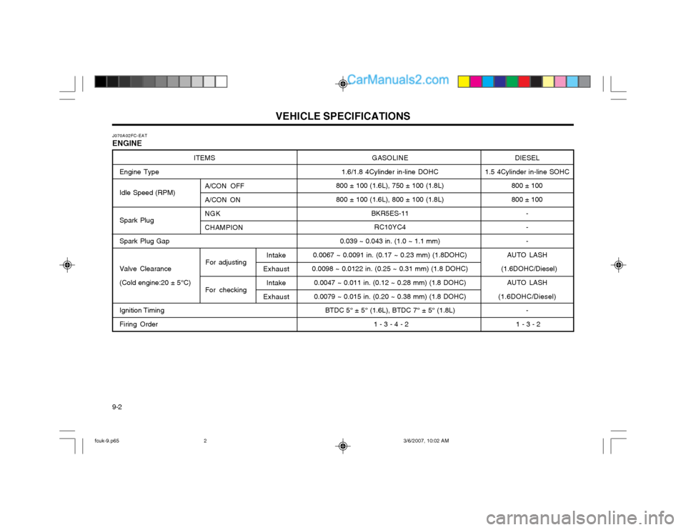
VEHICLE SPECIFICATIONS
9-2 GASOLINE
1.6/1.8 4Cylinder in-line DOHC
800 ± 100 (1.6L), 750 ± 100 (1.8L) 800 ± 100 (1.6L), 800 ± 100 (1.8L)
BKR5ES-11RC10YC4
0.039 ~ 0.043 in. (1.0 ~ 1.1 mm)
0.0067 ~ 0.0091 in. (0.17 ~ 0.23 mm) (1.8DOHC)
0.0098 ~ 0.0122 in. (0.25 ~ 0.31 mm) (1.8 DOHC)
0.0047 ~ 0.011 in. (0.12 ~ 0.28 mm) (1.8 DOHC) 0.0079 ~ 0.015 in. (0.20 ~ 0.38 mm) (1.8 DOHC) BTDC 5° ± 5° (1.6L), BTDC 7° ± 5° (1.8L)
1 - 3 - 4 - 2
ITEMS
Engine Type Idle Speed (RPM) Spark Plug Spark Plug Gap Valve Clearance (Cold engine:20 ± 5°C) Ignition Timing Firing Order
A/CON OFF A/CON ON NGKCHAMPION
For adjusting
For checking DIESEL
1.5 4Cylinder in-line SOHC 800 ± 100800 ± 100
---
AUTO LASH
(1.6DOHC/Diesel)
AUTO LASH
(1.6DOHC/Diesel) -
1 - 3 - 2
J070A02FC-EAT ENGINE
Intake
Exhaust
Intake
Exhaust
fcuk-9.p65 3/6/2007, 10:02 AM
2