Page 2457 of 2643

9Q – 8IROOF
DAEWOO V–121 BL4
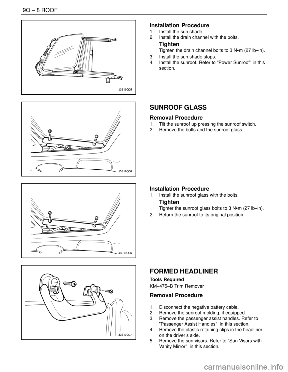
Installation Procedure
1. Install the sun shade.
2. Install the drain channel with the bolts.
Tighten
Tighten the drain channel bolts to 3 NSm (27 lb–in).
3. Install the sun shade stops.
4. Install the sunroof. Refer to ”Power Sunroof” in this
section.
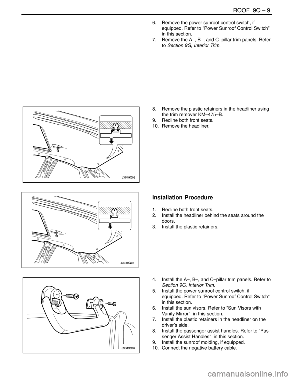
SUNROOF GLASS
Removal Procedure
1. Tilt the sunroof up pressing the sunroof switch.
2. Remove the bolts and the sunroof glass.
Installation Procedure
1. Install the sunroof glass with the bolts.
Tighten
Tighter the sunroof glass bolts to 3 NSm (27 lb–in).
2. Return the sunroof to its original position.
FORMED HEADLINER
Tools Required
KM–475–B Trim Remover
Removal Procedure
1. Disconnect the negative battery cable.
2. Remove the sunroof molding, if equipped.
3. Remove the passenger assist handles. Refer to
”Passenger Assist Handles” in this section.
4. Remove the plastic retaining clips in the headliner
on the driver’s side.
5. Remove the sun visors. Refer to ”Sun Visors with
Vanity Mirror” in this section.
Page 2458 of 2643

ROOF 9Q – 9
DAEWOO V–121 BL4
6. Remove the power sunroof control switch, if
equipped. Refer to ”Power Sunroof Control Switch”
in this section.
7. Remove the A–, B–, and C–pillar trim panels. Refer
to Section 9G, Interior Trim.
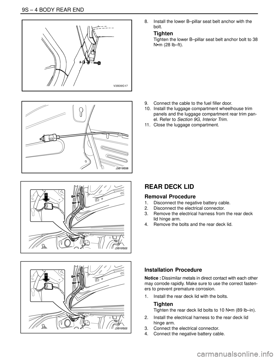
8. Remove the plastic retainers in the headliner using
the trim remover KM–475–B.
9. Recline both front seats.
10. Remove the headliner.
Installation Procedure
1. Recline both front seats.
2. Install the headliner behind the seats around the
doors.
3. Install the plastic retainers.
4. Install the A–, B–, and C–pillar trim panels. Refer to
Section 9G, Interior Trim.
5. Install the power sunroof control switch, if
equipped. Refer to ”Power Sunroof Control Switch”
in this section.
6. Install the sun visors. Refer to ”Sun Visors with
Vanity Mirror” in this section.
7. Install the plastic retainers in the headliner on the
driver’s side.
8. Install the passenger assist handles. Refer to ”Pas-
senger Assist Handles” in this section.
9. Install the sunroof molding, if equipped.
10. Connect the negative battery cable.
Page 2460 of 2643
ROOF 9Q – 11
DAEWOO V–121 BL4
POWER SUNROOF CONTROL
SWITCH
Removal Procedure
1. Disconnect the negative battery cable.
2. Pry off the interior courtesy lamp lens.
3. Remove the screws and the switch.
4. Disconnect the electrical connector.
Installation Procedure
1. Connect the electrical connector.
Notice : Dissimilar metals in direct contact with each other
may corrode rapidly. Make sure to use the correct fasten-
ers to prevent premature corrosion.
2. Install the sunroof control switch with the screws.
Tighten
Tighten the power sunroof control switch screws to 2
NSm (18 lb–in).
3. Install the interior courtesy lamp lens.
4. Connect the negative battery cable.
Page 2472 of 2643

SECTION : 9S
BODY REAR END
CAUTION : Disconnect the negative battery cable before removing or installing any electrical unit or when a tool
or equipment could easily come in contact with exposed electrical terminals. Disconnecting this cable will help
prevent personal injury and damage to the vehicle. The ignition must also be in LOCK unless otherwise noted.
TABLE OF CONTENTS
SPECIFICATIONS9S–1 . . . . . . . . . . . . . . . . . . . . . . . . . .
Fastener Tightening Specifications 9S–1. . . . . . . . . . .
MAINTENANCE AND REPAIR9S–2 . . . . . . . . . . . . . . .
ON–VEHICLE SERVICE 9S–2. . . . . . . . . . . . . . . . . . . . .
Fuel Filler Door 9S–2. . . . . . . . . . . . . . . . . . . . . . . . . . . .
Fuel Filler Door Remote Handle and Cable 9S–2. . . .
Rear Deck Lid 9S–4. . . . . . . . . . . . . . . . . . . . . . . . . . . . .
Rear Deck Lid Torque Rods 9S–5. . . . . . . . . . . . . . . . .
Luggage Compartment Lock Cylinder 9S–5. . . . . . . .
Luggage Compartment Lock Striker 9S–6. . . . . . . . . .
Luggage Compartment Lock 9S–6. . . . . . . . . . . . . . . . Weatherstrip 9S–7. . . . . . . . . . . . . . . . . . . . . . . . . . . . . .
Hatchback Weatherstrip 9S–7. . . . . . . . . . . . . . . . . . . .
Hatchback Door 9S–8. . . . . . . . . . . . . . . . . . . . . . . . . . .
Gas Support Assemblies 9S–8. . . . . . . . . . . . . . . . . . .
Hatchback Door Lock Striker 9S–9. . . . . . . . . . . . . . . .
Hatchback Door Lock 9S–9. . . . . . . . . . . . . . . . . . . . . .
GENERAL DESCRIPTION AND SYSTEM
OPERATION9S–10 . . . . . . . . . . . . . . . . . . . . . . . . . . . . .
Fuel Filler Door 9S–10. . . . . . . . . . . . . . . . . . . . . . . . . . .
Rear Deck Lid (Notchback) 9S–10. . . . . . . . . . . . . . . .
Hatchback Door 9S–10. . . . . . . . . . . . . . . . . . . . . . . . . .
SPECIFICATIONS
FASTENER TIGHTENING SPECIFICATIONS
ApplicationNSmLb–FtLb–In
Fuel Filler Door Screws4–35
Fuel Filler Door Remote Cable Handle Cover Screw3–27
Fuel Filler Door Remote Cable Handle Screws10–89
Lower B–Pillar Seat Belt Anchor Bolt3828–
Luggage Compartment Lock Cylinder Nuts8–71
Luggage Compartment Lock Screws6–53
Luggage Compartment Lock Striker Bolts8–71
Rear Deck Lid Bolts10–89
Page 2475 of 2643

9S – 4IBODY REAR END
DAEWOO V–121 BL4
8. Install the lower B–pillar seat belt anchor with the
bolt.
Tighten
Tighten the lower B–pillar seat belt anchor bolt to 38
NSm (28 lb–ft).
9. Connect the cable to the fuel filler door.
10. Install the luggage compartment wheelhouse trim
panels and the luggage compartment rear trim pan-
el. Refer to Section 9G, Interior Trim.
11. Close the luggage compartment.
REAR DECK LID
Removal Procedure
1. Disconnect the negative battery cable.
2. Disconnect the electrical connector.
3. Remove the electrical harness from the rear deck
lid hinge arm.
4. Remove the bolts and the rear deck lid.
Installation Procedure
Notice : Dissimilar metals in direct contact with each other
may corrode rapidly. Make sure to use the correct fasten-
ers to prevent premature corrosion.
1. Install the rear deck lid with the bolts.
Tighten
Tighten the rear deck lid bolts to 10 NSm (89 lb–in).
2. Install the electrical harness to the rear deck lid
hinge arm.
3. Connect the electrical connector.
4. Connect the negative battery cable.
Page 2477 of 2643

9S – 6IBODY REAR END
DAEWOO V–121 BL4
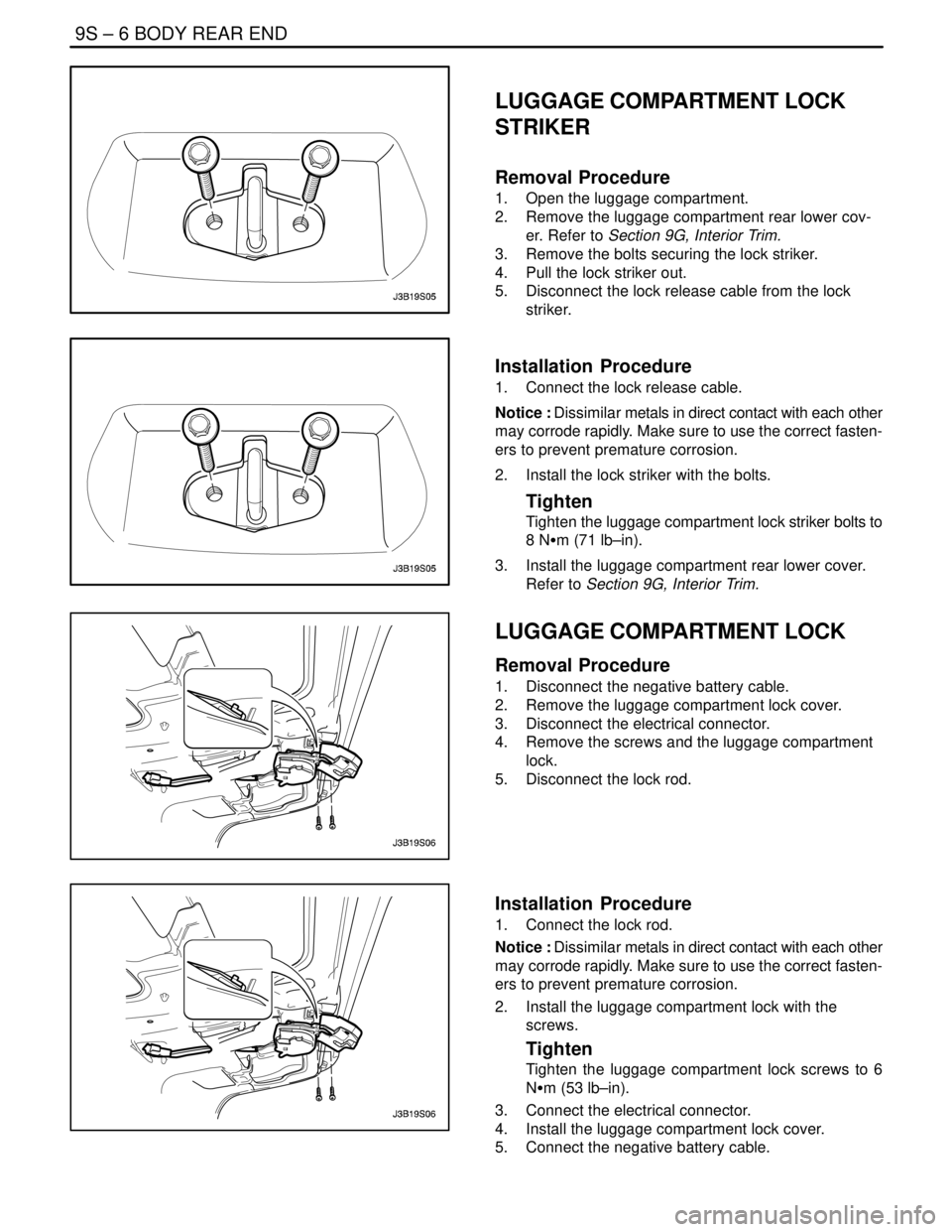
LUGGAGE COMPARTMENT LOCK
STRIKER
Removal Procedure
1. Open the luggage compartment.
2. Remove the luggage compartment rear lower cov-
er. Refer to Section 9G, Interior Trim.
3. Remove the bolts securing the lock striker.
4. Pull the lock striker out.
5. Disconnect the lock release cable from the lock
striker.
Installation Procedure
1. Connect the lock release cable.
Notice : Dissimilar metals in direct contact with each other
may corrode rapidly. Make sure to use the correct fasten-
ers to prevent premature corrosion.
2. Install the lock striker with the bolts.
Tighten
Tighten the luggage compartment lock striker bolts to
8 NSm (71 lb–in).
3. Install the luggage compartment rear lower cover.
Refer to Section 9G, Interior Trim.
LUGGAGE COMPARTMENT LOCK
Removal Procedure
1. Disconnect the negative battery cable.
2. Remove the luggage compartment lock cover.
3. Disconnect the electrical connector.
4. Remove the screws and the luggage compartment
lock.
5. Disconnect the lock rod.
Installation Procedure
1. Connect the lock rod.
Notice : Dissimilar metals in direct contact with each other
may corrode rapidly. Make sure to use the correct fasten-
ers to prevent premature corrosion.
2. Install the luggage compartment lock with the
screws.
Tighten
Tighten the luggage compartment lock screws to 6
NSm (53 lb–in).
3. Connect the electrical connector.
4. Install the luggage compartment lock cover.
5. Connect the negative battery cable.
Page 2482 of 2643

SECTION : 9T1
REMOTE KEYLESS ENTRY AND ANTI–THEFT
SYSTEM
CAUTION : Disconnect the negative battery cable before removing or installing any electrical unit or when a tool
or equipment could easily come in contact with exposed electrical terminals. Disconnecting this cable will help
prevent personal injury and damage to the vehicle. The ignition must also be in LOCK unless otherwise noted.
TABLE OF CONTENTS
SPECIFICATIONS 9T1–1 . . . . . . . . . . . . . . . . . . . . . . . . .
Fastener Tightening Specifications 9T1–1. . . . . . . . . .
SCHEMATIC AND ROUTING DIAGRAMS9T1–2 . . . .
Notchback Remote Keyless Entry and Anti–Theft
System 9T1–2. . . . . . . . . . . . . . . . . . . . . . . . . . . . . . . .
Hatchback Remote Keyless Entry and Anti–Theft
System 9T1–3. . . . . . . . . . . . . . . . . . . . . . . . . . . . . . . .
Control Module/Receiver Connector 9T1–4. . . . . . . . .
MAINTENANCE AND REPAIR9T1–5 . . . . . . . . . . . . . .
ON–VEHICLE SERVICE 9T1–5. . . . . . . . . . . . . . . . . . . .
Control Module/Receiver 9T1–5. . . . . . . . . . . . . . . . . . .
Siren (General Only) 9T1–5. . . . . . . . . . . . . . . . . . . . . . Remote Keyless Entry Transmitter
Programming 9T1–7. . . . . . . . . . . . . . . . . . . . . . . . . . .
GENERAL DESCRIPTION AND SYSTEM
OPERATION9T1–8 . . . . . . . . . . . . . . . . . . . . . . . . . . . . .
Remote Keyless Entry and Anti–Theft System 9T1–8
Remote Locking and Unlocking 9T1–8. . . . . . . . . . . . .
Security Indicator 9T1–8. . . . . . . . . . . . . . . . . . . . . . . . .
Intrusion Sensing 9T1–8. . . . . . . . . . . . . . . . . . . . . . . . .
Siren (General Only) 9T1–8. . . . . . . . . . . . . . . . . . . . . .
Vehicle Locator 9T1–8. . . . . . . . . . . . . . . . . . . . . . . . . . .
Autolocking (Safety Lock) 9T1–9. . . . . . . . . . . . . . . . . .
Control Module/Receiver 9T1–9. . . . . . . . . . . . . . . . . . .
Fault or Alarm Indication 9T1–9. . . . . . . . . . . . . . . . . . .
SPECIFICATIONS
FASTENER TIGHTENING SPECIFICATIONS
ApplicationNSmLb–FtLb–In
Siren Braket Mounting Bolts.8–71
Page 2485 of 2643
9T1 – 4IREMOTE KEYLESS ENTRY AND ANTI–THEFT SYSTEM
DAEWOO V–121 BL4
CONTROL MODULE/RECEIVER CONNECTOR
TerminalColorDescription
1YELSiren
2BLKGround
3––
4LT BLUDoor and Trunk Tamper Switch
5PNK/BLKTrunk Open Switch
6––
7PNK/DKBLUHood Open Switch
8PPLDoor contact Switch
9LT BLU/BLKUnlock
10LT GRN/WHTLock
11YELUnlock
12LT GRNAnti–Theft Door Locking Switch
13DK BLURight Turn Signal Bulb
14––
15PNKIgnition+
16––
17LT GRNDiagnostic Communication
18LT GRN/REDKey Reminder Switch
19YEL/DK GRNSecurity Indicator
20PPLAnti–Theft Door Locking Switch
21––
22––
23––
24BRNTrunk Open Switch
25ORNBattery+
26LT BLULeft Turn Signal Bulb