Page 2434 of 2643

9P – 14IDOORS
DAEWOO V–121 BL4
StepNo Yes Value(s) Action
181. Remove the trim panel from the rear door
which has an inoperative power window.
2. Move a vehicle battery close enough to the
door so that the window motor can be pow-
ered directly from the battery with jumper
wires.
3. Disconnect the the two–pin window motor
connector in the door.
Important : To prevent the fuse in the jumper wire
from blowing, do not touch the jumper wires togeth-
er.
1. Attach a jumper wire between the negative
battery terminal and one of the terminals in
the two–pin window motor connector.
2. Attach a fused jumper wire between the posi-
tive battery terminal and the remaining termi-
nal in the two–pin power window motor con-
nector. Unless the motor is at the end of its
travel, the power window should move with
the jumpers attached.
3. To move the power window in the opposite
direction, reverse the jumper wire connec-
tions at the power window motor connector.
Does the power window operate in both direc-
tions when the motor is operated directly from
a battery?–Go to
Step 20Go to
Step 19
19Replace the power window motor.
Is the repair complete?–System
OK–
201. Make sure the window lock on the main
switch is off.
2. Turn the ignition ON.
3. At the rear power window switch connector,
check the voltage at terminal 1.
Is the voltage equal to the specified value?11–14vGo to
Step 21Go to
Step 29
211. At the power window motor two–pin connec-
tor, use an ohmmeter to measure the resist-
ance of the power window motor. Record the
resistance.
2. Re–connect the two–pin power window motor
connector.
3. Disconnect the rear power window switch
connector.
4. Use an ohmmeter to measure between termi-
nals 2 and 6 of the rear power window switch
connector.
Is the resistance measured at the rear power
window switch connector equal to the resist-
ance previously measured at the rear power
window motor connector?–Go to
Step 23Go to
Step 22
22Repair the open circuit between the rear pow-
er window switch and the rear power window
motor connector.
Is the repair complete?–System
OK–
Page 2443 of 2643

DOORS 9P – 23
DAEWOO V–121 BL4
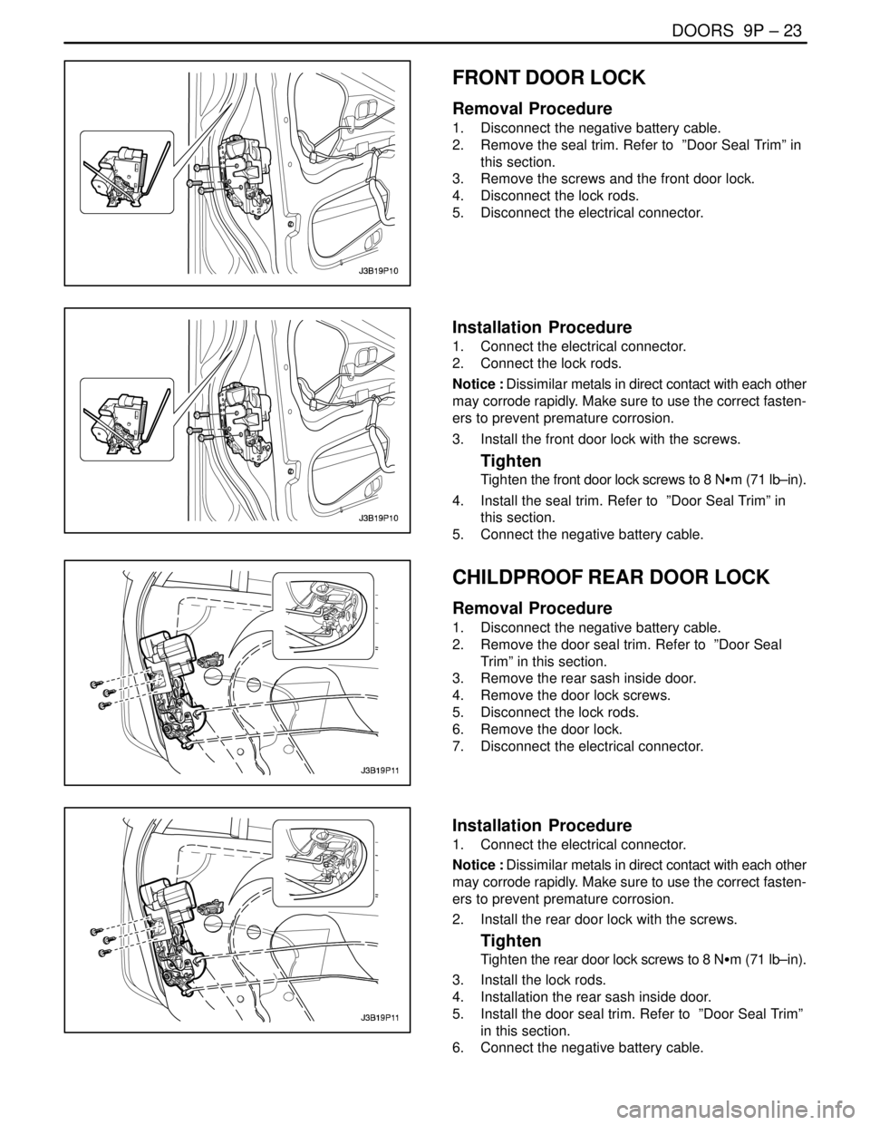
FRONT DOOR LOCK
Removal Procedure
1. Disconnect the negative battery cable.
2. Remove the seal trim. Refer to ”Door Seal Trim” in
this section.
3. Remove the screws and the front door lock.
4. Disconnect the lock rods.
5. Disconnect the electrical connector.
Installation Procedure
1. Connect the electrical connector.
2. Connect the lock rods.
Notice : Dissimilar metals in direct contact with each other
may corrode rapidly. Make sure to use the correct fasten-
ers to prevent premature corrosion.
3. Install the front door lock with the screws.
Tighten
Tighten the front door lock screws to 8 NSm (71 lb–in).
4. Install the seal trim. Refer to ”Door Seal Trim” in
this section.
5. Connect the negative battery cable.
CHILDPROOF REAR DOOR LOCK
Removal Procedure
1. Disconnect the negative battery cable.
2. Remove the door seal trim. Refer to ”Door Seal
Trim” in this section.
3. Remove the rear sash inside door.
4. Remove the door lock screws.
5. Disconnect the lock rods.
6. Remove the door lock.
7. Disconnect the electrical connector.
Installation Procedure
1. Connect the electrical connector.
Notice : Dissimilar metals in direct contact with each other
may corrode rapidly. Make sure to use the correct fasten-
ers to prevent premature corrosion.
2. Install the rear door lock with the screws.
Tighten
Tighten the rear door lock screws to 8 NSm (71 lb–in).
3. Install the lock rods.
4. Installation the rear sash inside door.
5. Install the door seal trim. Refer to ”Door Seal Trim”
in this section.
6. Connect the negative battery cable.
Page 2446 of 2643

9P – 26IDOORS
DAEWOO V–121 BL4
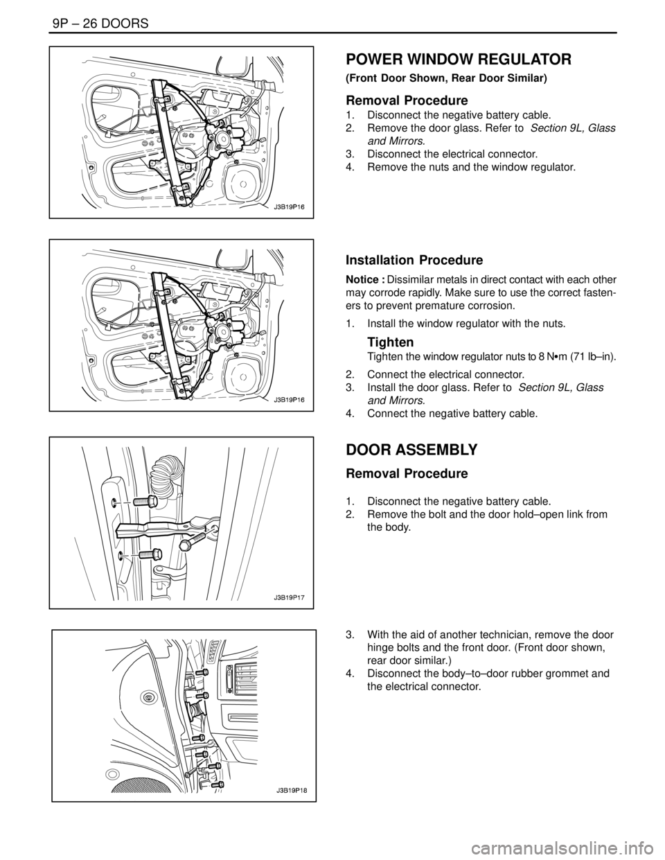
POWER WINDOW REGULATOR
(Front Door Shown, Rear Door Similar)
Removal Procedure
1. Disconnect the negative battery cable.
2. Remove the door glass. Refer to Section 9L, Glass
and Mirrors.
3. Disconnect the electrical connector.
4. Remove the nuts and the window regulator.
Installation Procedure
Notice : Dissimilar metals in direct contact with each other
may corrode rapidly. Make sure to use the correct fasten-
ers to prevent premature corrosion.
1. Install the window regulator with the nuts.
Tighten
Tighten the window regulator nuts to 8 NSm (71 lb–in).
2. Connect the electrical connector.
3. Install the door glass. Refer to Section 9L, Glass
and Mirrors.
4. Connect the negative battery cable.
DOOR ASSEMBLY
Removal Procedure
1. Disconnect the negative battery cable.
2. Remove the bolt and the door hold–open link from
the body.
3. With the aid of another technician, remove the door
hinge bolts and the front door. (Front door shown,
rear door similar.)
4. Disconnect the body–to–door rubber grommet and
the electrical connector.
Page 2447 of 2643

DOORS 9P – 27
DAEWOO V–121 BL4
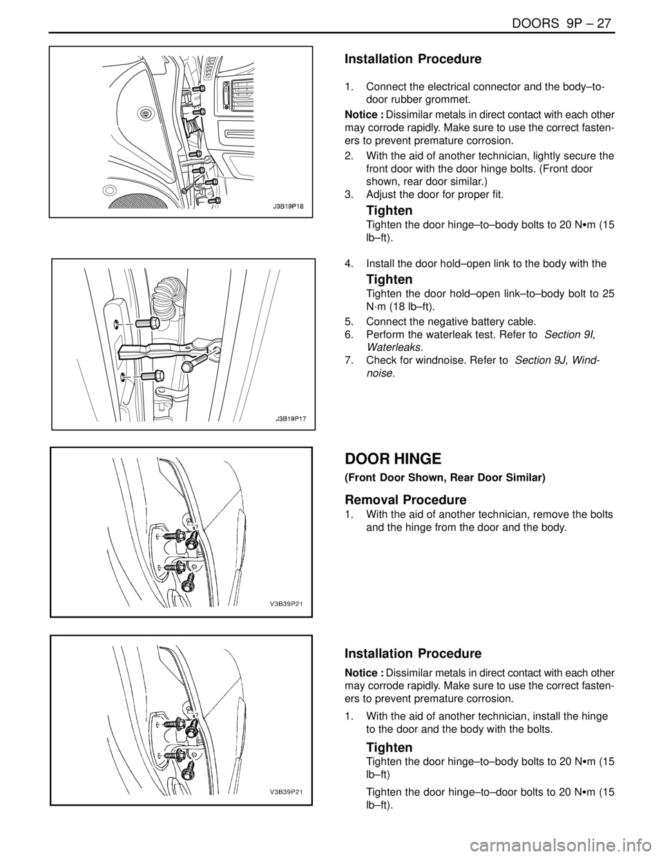
Installation Procedure
1. Connect the electrical connector and the body–to-
door rubber grommet.
Notice : Dissimilar metals in direct contact with each other
may corrode rapidly. Make sure to use the correct fasten-
ers to prevent premature corrosion.
2. With the aid of another technician, lightly secure the
front door with the door hinge bolts. (Front door
shown, rear door similar.)
3. Adjust the door for proper fit.
Tighten
Tighten the door hinge–to–body bolts to 20 NSm (15
lb–ft).
4. Install the door hold–open link to the body with the
Tighten
Tighten the door hold–open link–to–body bolt to 25
N·m (18 lb–ft).
5. Connect the negative battery cable.
6. Perform the waterleak test. Refer to Section 9I,
Waterleaks.
7. Check for windnoise. Refer to Section 9J, Wind-
noise.
DOOR HINGE
(Front Door Shown, Rear Door Similar)
Removal Procedure
1. With the aid of another technician, remove the bolts
and the hinge from the door and the body.
Installation Procedure
Notice : Dissimilar metals in direct contact with each other
may corrode rapidly. Make sure to use the correct fasten-
ers to prevent premature corrosion.
1. With the aid of another technician, install the hinge
to the door and the body with the bolts.
Tighten
Tighten the door hinge–to–body bolts to 20 NSm (15
lb–ft)
Tighten the door hinge–to–door bolts to 20 NSm (15
lb–ft).
Page 2450 of 2643

SECTION : 9Q
ROOF
CAUTION : Disconnect the negative battery cable before removing or installing any electrical unit or when a tool
or equipment could easily come in contact with exposed electrical terminals. Disconnecting this cable will help
prevent personal injury and damage to the vehicle. The ignition must also be in LOCK unless otherwise noted.
TABLE OF CONTENTS
SPECIFICATIONS9Q–2 . . . . . . . . . . . . . . . . . . . . . . . . . .
Fastener Tightening Specifications 9Q–2. . . . . . . . . . .
SPECIAL TOOLS9Q–2 . . . . . . . . . . . . . . . . . . . . . . . . . . .
Special Tools Table 9Q–2. . . . . . . . . . . . . . . . . . . . . . . .
SCHEMATIC AND ROUTING DIAGRAMS9Q–3 . . . . .
Power Sunroof System 9Q–3. . . . . . . . . . . . . . . . . . . . .
DIAGNOSIS9Q–4 . . . . . . . . . . . . . . . . . . . . . . . . . . . . . . . .
Power Sunroof 9Q–4. . . . . . . . . . . . . . . . . . . . . . . . . . . .
MAINTENANCE AND REPAIR9Q–6 . . . . . . . . . . . . . . .
ON–VEHICLE SERVICE 9Q–6. . . . . . . . . . . . . . . . . . . . .
Power Sunroof 9Q–6. . . . . . . . . . . . . . . . . . . . . . . . . . . .
Sun Shade 9Q–7. . . . . . . . . . . . . . . . . . . . . . . . . . . . . . . . Sunroof Glass 9Q–8. . . . . . . . . . . . . . . . . . . . . . . . . . . . .
Formed Headliner 9Q–8. . . . . . . . . . . . . . . . . . . . . . . . .
Sun Visors with Vanity Mirror 9Q–10. . . . . . . . . . . . . . .
Passenger Assist Handles 9Q–10. . . . . . . . . . . . . . . . .
Power Sunroof Control Switch 9Q–11. . . . . . . . . . . . . .
GENERAL DESCRIPTION AND SYSTEM
OPERATION9Q–12 . . . . . . . . . . . . . . . . . . . . . . . . . . . . .
Roof 9Q–12. . . . . . . . . . . . . . . . . . . . . . . . . . . . . . . . . . . .
Power Sunroof/Sunroof Control Switch 9Q–12. . . . . .
Sun Visors with Vanity Mirror 9Q–12. . . . . . . . . . . . . . .
Passenger Assist Handles 9Q–12. . . . . . . . . . . . . . . . .
Coat Hooks 9Q–12. . . . . . . . . . . . . . . . . . . . . . . . . . . . . .
Page 2453 of 2643

9Q – 4IROOF
DAEWOO V–121 BL4
DIAGNOSIS
POWER SUNROOF
Power Sunroof Does Not Work
StepActionValue(s)YesNo
1Check fuse F8.
Is either fuse blown?–Go to Step 2Go to Step 3
21. Check for a short circuit and repair it, if neces-
sary.
2. Replace the blown fuse.
Is the repair complete?–System OK–
31. Turn the ignition on.
2. Check the voltages at fuse F8.
Are both voltages equal to the specified value?11 – 14 vGo to Step 5Go to Step 4
4Repair the power supply to the fuse which did not in-
dicate battery voltage with the ignition on.
Is the repair complete?–System OK–
51. Disconnect the interior courtesy lamp/power
sunroof control switch connector.
2. Turn the ignition on.
3. Check the voltage at terminal 5 of the interior
courtesy lamp/power sunroof control switch
connector.
Is the voltage equal to the specified value?11–14 vGo to Step 7Go to Step 6
6Repair the open circuit between fuse F8 and the inte-
rior courtesy lamp/power sunroof control switch con-
nector.
Is the repair complete?–System OK–
71. Reconnect the interior courtesy lamp/power
sunroof control switch connector.
2. With the sunroof switch in the OPEN position,
check the voltage at terminal 4 of the interior
courtesy lamp/power sunroof control switch
connector.
3. With the sunroof switch in the CLOSE position,
check the voltage at terminal 6 of the interior
courtesy lamp/power sunroof control switch
connector.
Do both voltages equal the specified value?11 – 14 vGo to Step 9Go to Step 8
8Replace the interior courtesy lamp/power sunroof
control switch.
Is the repair complete?–System OK–
91. Disconnect the sunroof module connector.
2. With the sunroof switch in the OPEN position,
check the voltage at terminal 1 of the sunroof
module connector.
3. With the sunroof switch in the CLOSE position,
check the voltage at terminal 6 of the sunroof
module connector.
Are the voltages equal to the specified value?11–14 vGo to Step 11Go to Step 10
Page 2455 of 2643
9Q – 6IROOF
DAEWOO V–121 BL4
MAINTENANCE AND REPAIR
ON–VEHICLE SERVICE
POWER SUNROOF
Removal Procedure
1. Disconnect the negative battery cable.
2. Remove the headliner. Refer to ”Formed Headliner”
in this section.
3. Remove the drain hoses.
4. Disconnect the electrical connectors.
5. Remove the screws and the motor.
6. Remove the motor control module.
7. Remove the bolts and the housing from the vehicle.
Page 2456 of 2643
ROOF 9Q – 7
DAEWOO V–121 BL4
Installation Procedure
Notice : Dissimilar metals in direct contact with each other
may corrode rapidly. Make sure to use the correct fasten-
ers to prevent premature corrosion.
1. Install the housing to the roof of the vehicle with the
bolts.
Tighten
Tighten the sunroof housing bolts to 10 NSm (89 lb–
in).
2. Install the motor control module.
3. Install the motor with the screws.
Tighten
Tighten the sunroof motor screws to 3 NSm (27 lb–in).
4. Connect the electrical connectors.
5. Install the drain hoses.
6. Install the headliner. Refer to ”Formed Headliner” in
this section.
7. Connect the negative battery cable.
SUN SHADE
Removal Procedure
1. Remove the sunroof. Refer to ”Power Sunroof” in
this section.
2. Remove the sunshade steps.
3. Remove the bolts and the drain channel.
4. Remove the sun shade.