Page 2322 of 2643
INSTRUMENTATION/DRIVER INFORMATION 9E – 23
DAEWOO V–121 BL4
INSTRUMENT CLUSTER
Removal Procedure
1. Disconnect the negative battery cable.
2. Remove the instrument cluster trim panel.
3. Remove the screws and the instrument cluster.
4. Disconnect the electrical connectors.
Installation Procedure
1. Connect the electrical connectors.
2. Install the instrument cluster with the screws.
Tighten
Tighten the instrument cluster screw to 4 NSm (35 lb–
in).
3. Install the instrument cluster trim panel.
4. Connect the negative battery cable.
INSTRUMENT CLUSTER DIMMER
SWITCH
Removal Procedure
1. Remove the instrument cluster dimmer switch as-
sembly.
2. Disconnect the electrical connectors.
Page 2323 of 2643

9E – 24IINSTRUMENTATION/DRIVER INFORMATION
DAEWOO V–121 BL4
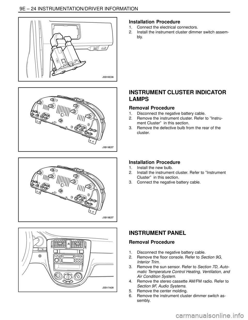
Installation Procedure
1. Connect the electrical connectors.
2. Install the instrument cluster dimmer switch assem-
bly.
INSTRUMENT CLUSTER INDICATOR
LAMPS
Removal Procedure
1. Disconnect the negative battery cable.
2. Remove the instrument cluster. Refer to ”Instru-
ment Cluster” in this section.
3. Remove the defective bulb from the rear of the
cluster.
Installation Procedure
1. Install the new bulb.
2. Install the instrument cluster. Refer to ”Instrument
Cluster” in this section.
3. Connect the negative battery cable.
INSTRUMENT PANEL
Removal Procedure
1. Disconnect the negative battery cable.
2. Remove the floor console. Refer to Section 9G,
Interior Trim.
3. Remove the sun sensor. Refer to Section 7D, Auto-
matic Temperature Control Heating, Ventilation, and
Air Condition System.
4. Remove the stereo cassette AM/FM radio. Refer to
Section 9F, Audio Systems.
5. Remove the center molding.
6. Remove the instrument cluster dimmer switch as-
sembly.
Page 2327 of 2643

9E – 28IINSTRUMENTATION/DRIVER INFORMATION
DAEWOO V–121 BL4
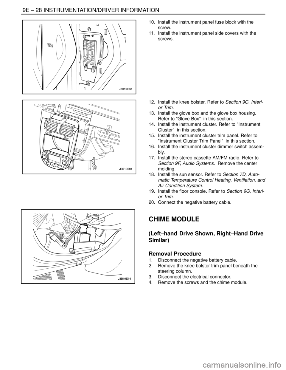
10. Install the instrument panel fuse block with the
screw.
11. Install the instrument panel side covers with the
screws.
12. Install the knee bolster. Refer to Section 9G, Interi-
or Trim.
13. Install the glove box and the glove box housing.
Refer to ”Glove Box” in this section.
14. Install the instrument cluster. Refer to ”Instrument
Cluster” in this section.
15. Install the instrument cluster trim panel. Refer to
”Instrument Cluster Trim Panel” in this section.
16. Install the instrument cluster dimmer switch assem-
bly.
17. Install the stereo cassette AM/FM radio. Refer to
Section 9F, Audio Systems. Remove the center
molding.
18. Install the sun sensor. Refer to Section 7D, Auto-
matic Temperature Control Heating, Ventilation, and
Air Condition System.
19. Install the floor console. Refer to Section 9G, Interi-
or Trim.
20. Connect the negative battery cable.
CHIME MODULE
(Left–hand Drive Shown, Right–Hand Drive
Similar)
Removal Procedure
1. Disconnect the negative battery cable.
2. Remove the knee bolster trim panel beneath the
steering column.
3. Disconnect the electrical connector.
4. Remove the screws and the chime module.
Page 2328 of 2643
INSTRUMENTATION/DRIVER INFORMATION 9E – 29
DAEWOO V–121 BL4
Installation Procedure
1. Install the chime module with the screws.
Tighten
Tighten the chime module screws to 4 NSm (35 lb–in).
2. Connect the electrical connector.
3. Install the knee bolster trim panel beneath the
steering column.
4. Connect the negative battery cable.
Page 2330 of 2643

SECTION : 9F
AUDIO SYSTEMS
CAUTION : Disconnect the negative battery cable before removing or installing any electrical unit or when a tool
or equipment could easily come in contact with exposed electrical terminals. Disconnecting this cable will help
prevent personal injury and damage to the vehicle. The ignition must also be in LOCK unless otherwise noted.
TABLE OF CONTENTS
SPECIFICATIONS9F–1 . . . . . . . . . . . . . . . . . . . . . . . . . .
Fastener Tightening Specifications 9F–1. . . . . . . . . . .
SCHEMATIC AND ROUTING DIAGRAMS9F–2 . . . . .
Audio System Circuit 9F–2. . . . . . . . . . . . . . . . . . . . . . .
DIAGNOSIS9F–3 . . . . . . . . . . . . . . . . . . . . . . . . . . . . . . . .
Stereo Cassette AM/FM Radio 9F–3. . . . . . . . . . . . . .
Speakers 9F–5. . . . . . . . . . . . . . . . . . . . . . . . . . . . . . . . .
MAINTENANCE AND REPAIR9F–7 . . . . . . . . . . . . . . .
ON–VEHICLE SERVICE 9F–7. . . . . . . . . . . . . . . . . . . . .
Stereo Cassette AM/FM Radio 9F–7. . . . . . . . . . . . . .
Audio Remote Controller 9F–7. . . . . . . . . . . . . . . . . . . . Notchback CD Changer 9F–8. . . . . . . . . . . . . . . . . . . .
Door Speakers 9F–8. . . . . . . . . . . . . . . . . . . . . . . . . . . .
Tweeter Speakers 9F–9. . . . . . . . . . . . . . . . . . . . . . . . .
Glass Antenna Module 9F–9. . . . . . . . . . . . . . . . . . . . .
Hatchback Windshield Antenna Module 9F–10. . . . . .
GENERAL DESCRIPTION AND SYSTEM
OPERATION9F–11 . . . . . . . . . . . . . . . . . . . . . . . . . . . . . .
Stereo Cassette AM/FM Radio 9F–11. . . . . . . . . . . . . .
Audio Scurity System 9F–11. . . . . . . . . . . . . . . . . . . . . .
Speakers 9F–11. . . . . . . . . . . . . . . . . . . . . . . . . . . . . . . . .
Tape Player and Cassette Care 9F–11. . . . . . . . . . . . . .
Compact Disc Care 9F–11. . . . . . . . . . . . . . . . . . . . . . . .
SPECIFICATIONS
FASTENER TIGHTENING SPECIFICATIONS
ApplicationNSmLb–FtLb–In
Door Speaker Screws2–18
Rear Speaker Screws2–18
Glass Antenna Screws2–18
Page 2332 of 2643

AUDIO SYSTEMS 9F – 3
DAEWOO V–121 BL4
DIAGNOSIS
STEREO CASSETTE AM/FM RADIO
CD Player Inoperative, AM/FM Functions OK
StepActionValue(s)YesNo
1Using a good–quality CD, determine if the CD player
performs poorly or is inoperative.
Does the CD player function correctly?–Go to Step 2Go to Step 3
2Inform the customer that the problem is with the CD,
not the CD player.
Has the customer been informed?–System OK–
3Check the CD player for obstructions behind the
tape door.
Is an obstruction found?–Go to Step 4Go to Step 6
4Check to see if the obstruction can be removed.
Can the obstruction be removed?–Go to Step 5Go to Step 6
5Remove the obstruction.
Is the repair complete?–System OK–
6Replace the CD player.
Is the repair complete?–System OK–
AM/FM Cassette Radio Inoperative
StepActionValue(s)YesNo
1Check fuses F23 and F17.
Are fuses F23 and F17 blown?–Go to Step 2Go to Step 3
21. Check for a short circuit and repair it, if neces-
sary.
2. Replace the blown fuses.
Is the repair complete?–System OK–
31. Use a voltmeter to test for battery voltage at
fuse F23.
2. Turn the ignition ON and test for battery volt-
age at fuse F17.
Does the battery voltagematch the specified value at
fuses F23 and F17?11–14 vGo to Step 5Go to Step 4
4Repair the power supply circuit to the fuses.
Is the repair complete?–System OK–
51. Remove the cassette radio.
2. Turn the ignition ON.
3. Use a voltmeter to test for battery voltage at
the audio system connector terminals 4 and 5.
Does the battery voltage match the specified value
at both terminals?11–14 vGo to Step 7Go to Step 6
6Repair the open circuit between the audio system
connector and the fuse.
Is the repair complete?–System OK–
7Use an ohmmeter to test the ground circuit at the au-
dio system connector terminal 14.
Does the resistancematch the specified value?� 0 WGo to Step 9Go to Step 8
Page 2336 of 2643
AUDIO SYSTEMS 9F – 7
DAEWOO V–121 BL4
MAINTENANCE AND REPAIR
ON–VEHICLE SERVICE
STEREO CASSETTE AM/FM RADIO
Removal Procedure
1. Disconnect the negative battery cable.
2. Remove the center molding. Refer to Section 9E,
Instrumentation/Drive Information.
3. Remove the screws and the audio system.
4. Disconnect the audio system electrical connectors.
Installation Procedure
1. Connect the audio system electrical connectors.
Notice : Dissimilar metals in direct contact with each other
may corrode rapidly. Make sure to use the correct fasten-
ers to prevent premature corrosion.
2. Install the audio system with the screws.
Tighten
Tighten the audio system screws to 4 NSm (35 lb–in).
3. Install the center molding. Refer to Section 9E, In-
strumentation/Drive Information.
4. Connect the negative battery cable.
AUDIO REMOTE CONTROLLER
Removal Procedure
1. Disconnect the negative battery cable.
2. Remove the screws and the audio remote control-
ler.
Page 2337 of 2643
9F – 8IAUDIO SYSTEMS
DAEWOO V–121 BL4
Installation Procedure
1. Install the audio remote controller with the screws.
2. Connect the negative battery cable.
NOTCHBACK CD CHANGER
Removal Procedure
1. Disconnect the negative battery cable.
2. Disconnect the CD changer electrical connector.
3. Remove the bolts and the CD changer.
Installation Procedure
1. Install the CD changer with the bolts.
2. Connect the CD changer electrical connector.
3. Connect the negative battery cable.
DOOR SPEAKERS
Removal Procedure
1. Disconnect the negative battery cable.
2. Remove the door trim panel. Refer to Section 9G,
Interior Trim.
3. Disconnect the electrical connector.
4. Remove the screws and the door speaker.