Page 144 of 2643

1C2 – 24I1.8L DOHC ENGINE MECHANICAL
DAEWOO V–121 BL4
12. Install the exhaust camshaft gear.
13. While holding the exhaust camshaft firmly in place,
install the exhaust camshaft gear bolt.
Tighten
Tighten the exhaust camshaft gear bolt to 50 NSm (37
lb–ft) plus 60 degrees and 15 degrees using the angu-
lar torque gauge KM–470–B.
14. Install the camshaft cover and the camshaft cover
gasket.
15. Install the camshaft cover washers.
16. Install the camshaft cover bolts.
Tighten
Tighten the camshaft cover bolts to 8 NSm (71 lb–in).
17. Connect the ignition wires to the spark plugs.
18. Install the spark plug cover.
19. Install the spark plug cover bolts.
Tighten
Tighten the spark plug cover bolts to 8 NSm (71 lb–in).
20. Connect the breather tube to the camshaft cover.
21. Connect the engine ventilation hose to the cam-
shaft cover.
22. Install the timing belt. Refer to ”Timing Belt” in this
section.
TIMING BELT CHECK AND ADJUST
(Left–Hand Drive Shown, Right–Hand Drive
Similar)
Adjustment Procedure
1. Disconnect the negative battery cable.
2. Disconnect the manifold air temperature (MAT)
sensor connector.
3. Remove the air cleaner outlet hose from the throttle
body.
4. Remove the breather tube from the camshaft cover.
Page 145 of 2643
1.8L DOHC ENGINE MECHANICAL 1C2 – 25
DAEWOO V–121 BL4
5. Remove the air cleaner housing bolts.
6. Remove the air cleaner housing.
7. Remove the right front wheel. Refer to Section 2E,
Tires and Wheels.
8. Remove the right front wheel well splash shield.
9. Remove the serpentine accessory drive belt. Refer
to Section 6B, Power Steering Pump.
10. Remove the crankshaft pulley bolts.
11. Remove the crankshaft pulley.
12. Remove the right engine mount bracket. Refer to
”Engine Mount” in this section.
13. Remove the front timing belt cover bolts.
14. Remove the front timing belt cover.
15. Rotate the crankshaft at least one full turn clock-
wise using the crankshaft gear bolt.
16. Align the mark on the crankshaft gear with the
notch at the bottom of the rear timing belt cover.
Page 147 of 2643

1.8L DOHC ENGINE MECHANICAL 1C2 – 27
DAEWOO V–121 BL4
24. Install the front timing belt cover.
25. Install the front timing belt cover bolts.
Tighten
Tighten the front timing belt cover bolts to 6 NSm (53
lb–in).
26. Install the crankshaft pulley.
27. Install the crankshaft pulley bolt.
Tighten
Tighten the crankshaft pulley bolt to 20 NSm (15 lb–ft).
28. Install the right engine mount bracket. Refer to ”En-
gine Mount” in this section.
29. Install the serpentine accessory drive belt. Refer to
Section 6B, Power Steering Pump.
30. Install the right front wheel well splash shield.
31. Install the right front wheel. Refer to Section 2E,
Tires and Wheels.
32. Install the air cleaner housing.
33. Install the air cleaner housing bolts.
Tighten
Tighten the air cleaner housing bolts to 10 NSm (89 lb–
in).
34. Connect the air cleaner outlet hose to the throttle
body.
35. Connect the breather tube to the camshaft cover.
36. Connect the MAT sensor connector.
37. Connect the negative battery cable.
Page 148 of 2643
1C2 – 28I1.8L DOHC ENGINE MECHANICAL
DAEWOO V–121 BL4
TIMING BELT
Removal Procedure
1. Disconnect the negative battery cable.
2. Disconnect the manifold air temperature (MAT)
sensor connector.
3. Disconnect the air cleaner outlet hose from the
throttle body.
4. Disconnect the breather tube from the camshaft
cover.
5. Remove the air cleaner housing bolts.
6. Remove the air cleaner housing.
7. Remove the right front wheel. Refer to Section 2E,
Tires and Wheels.
8. Remove the right front wheel well splash shield.
9. Remove the serpentine accessory drive belt. Refer
to Section 6B, Power Steering Pump.
10. Remove the crankshaft pulley bolts.
11. Remove the crankshaft pulley.
12. Remove the right engine mount bracket. Refer to
”Engine Mount” in this section.
13. Remove the front timing belt cover bolts.
14. Remove the front timing belt cover.
Page 150 of 2643
1C2 – 30I1.8L DOHC ENGINE MECHANICAL
DAEWOO V–121 BL4
2. Align the timing marks on the camshaft gears, us-
ing the intake gear mark for the intake gear and the
exhaust gear mark for the exhaust gear.
3. Install the timing belt.
4. Turn the hex–key tab in a clockwise direction to
tension the belt. Turn until the pointer aligns with
the notch.
5. Install the automatic tensioner bolt.
Tighten
Tighten the automatic tensioner bolt to 25 NSm (18 lb–
ft).
6. Rotate the crankshaft two full turns clockwise using
the crankshaft pulley bolt.
7. Recheck the automatic tensioner pointer.
8. Install the front timing belt cover.
9. Install the front timing belt cover bolts.
Tighten
Tighten the front timing belt cover bolts to 6 NSm (53
lb–in).
10. Install the right engine mount bracket. Refer to ”En-
gine Mounts” in this section.
Page 151 of 2643
1.8L DOHC ENGINE MECHANICAL 1C2 – 31
DAEWOO V–121 BL4
11. Install the crankshaft pulley.
12. Install the crankshaft pulley bolts.
Tighten
Tighten the crankshaft pulley bolts to 20 NSm (15 lb–
ft).
13. Install the serpentine accessory drive belt. Refer to
Section 6B, Power Steering Pump.
14. Install the right front wheel well splash shield. Refer
to Section 9R, Body Front End.
15. Install the right front wheel. Refer to Section 2E,
Tires and Wheels.
16. Install the air cleaner housing.
17. Install the air cleaner housing bolts.
Tighten
Tighten the air cleaner housing bolts to 10 NSm (89 lb–
in).
18. Connect the air cleaner outlet hose to the throttle
body.
19. Connect the breather tube to the camshaft cover.
20. Connect the MAT sensor connector.
21. Connect the negative battery cable.
Page 153 of 2643

1.8L DOHC ENGINE MECHANICAL 1C2 – 33
DAEWOO V–121 BL4
Installation Procedure
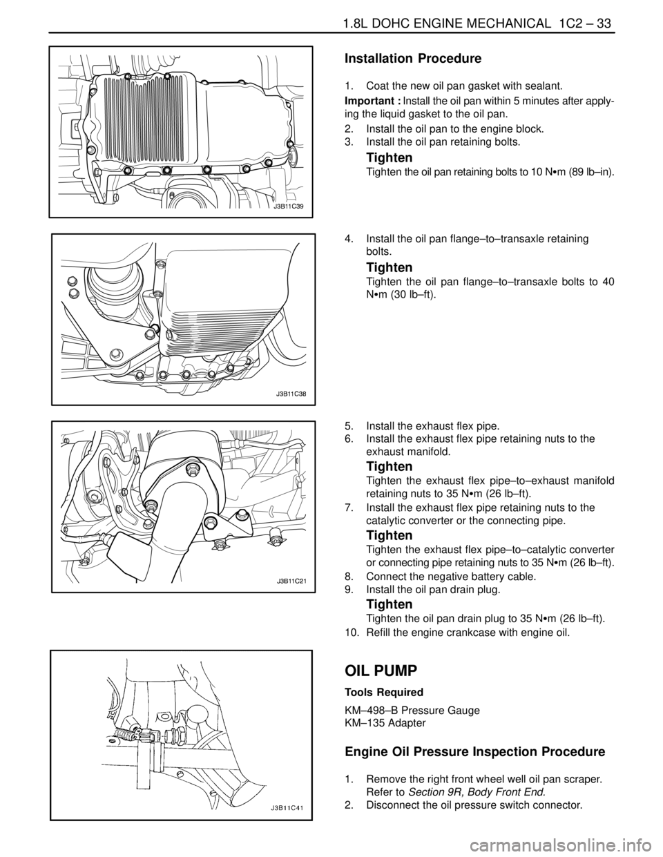
1. Coat the new oil pan gasket with sealant.
Important : Install the oil pan within 5 minutes after apply-
ing the liquid gasket to the oil pan.
2. Install the oil pan to the engine block.
3. Install the oil pan retaining bolts.
Tighten
Tighten the oil pan retaining bolts to 10 NSm (89 lb–in).
4. Install the oil pan flange–to–transaxle retaining
bolts.
Tighten
Tighten the oil pan flange–to–transaxle bolts to 40
NSm (30 lb–ft).
5. Install the exhaust flex pipe.
6. Install the exhaust flex pipe retaining nuts to the
exhaust manifold.
Tighten
Tighten the exhaust flex pipe–to–exhaust manifold
retaining nuts to 35 NSm (26 lb–ft).
7. Install the exhaust flex pipe retaining nuts to the
catalytic converter or the connecting pipe.
Tighten
Tighten the exhaust flex pipe–to–catalytic converter
or connecting pipe retaining nuts to 35 NSm (26 lb–ft).
8. Connect the negative battery cable.
9. Install the oil pan drain plug.
Tighten
Tighten the oil pan drain plug to 35 NSm (26 lb–ft).
10. Refill the engine crankcase with engine oil.
OIL PUMP
Tools Required
KM–498–B Pressure Gauge
KM–135 Adapter
Engine Oil Pressure Inspection Procedure
1. Remove the right front wheel well oil pan scraper.
Refer to Section 9R, Body Front End.
2. Disconnect the oil pressure switch connector.
Page 154 of 2643

1C2 – 34I1.8L DOHC ENGINE MECHANICAL
DAEWOO V–121 BL4
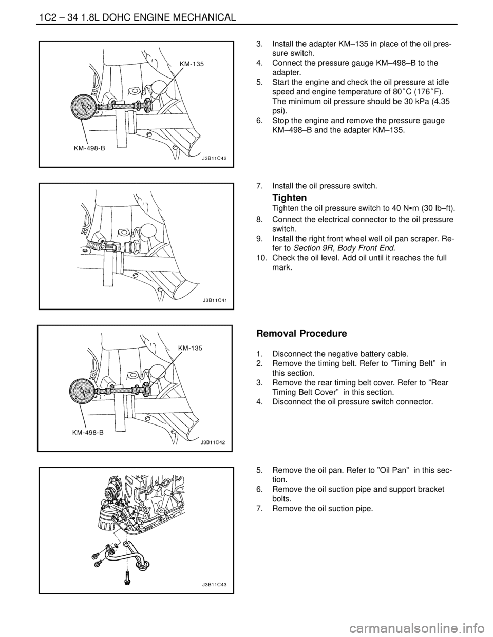
3. Install the adapter KM–135 in place of the oil pres-
sure switch.
4. Connect the pressure gauge KM–498–B to the
adapter.
5. Start the engine and check the oil pressure at idle
speed and engine temperature of 80°C (176°F).
The minimum oil pressure should be 30 kPa (4.35
psi).
6. Stop the engine and remove the pressure gauge
KM–498–B and the adapter KM–135.
7. Install the oil pressure switch.
Tighten
Tighten the oil pressure switch to 40 NSm (30 lb–ft).
8. Connect the electrical connector to the oil pressure
switch.
9. Install the right front wheel well oil pan scraper. Re-
fer to Section 9R, Body Front End.
10. Check the oil level. Add oil until it reaches the full
mark.
Removal Procedure
1. Disconnect the negative battery cable.
2. Remove the timing belt. Refer to ”Timing Belt” in
this section.
3. Remove the rear timing belt cover. Refer to ”Rear
Timing Belt Cover” in this section.
4. Disconnect the oil pressure switch connector.
5. Remove the oil pan. Refer to ”Oil Pan” in this sec-
tion.
6. Remove the oil suction pipe and support bracket
bolts.
7. Remove the oil suction pipe.