2004 DAEWOO LACETTI Section 6
[x] Cancel search: Section 6Page 193 of 2643
1.8L DOHC ENGINE MECHANICAL 1C2 – 73
DAEWOO V–121 BL4
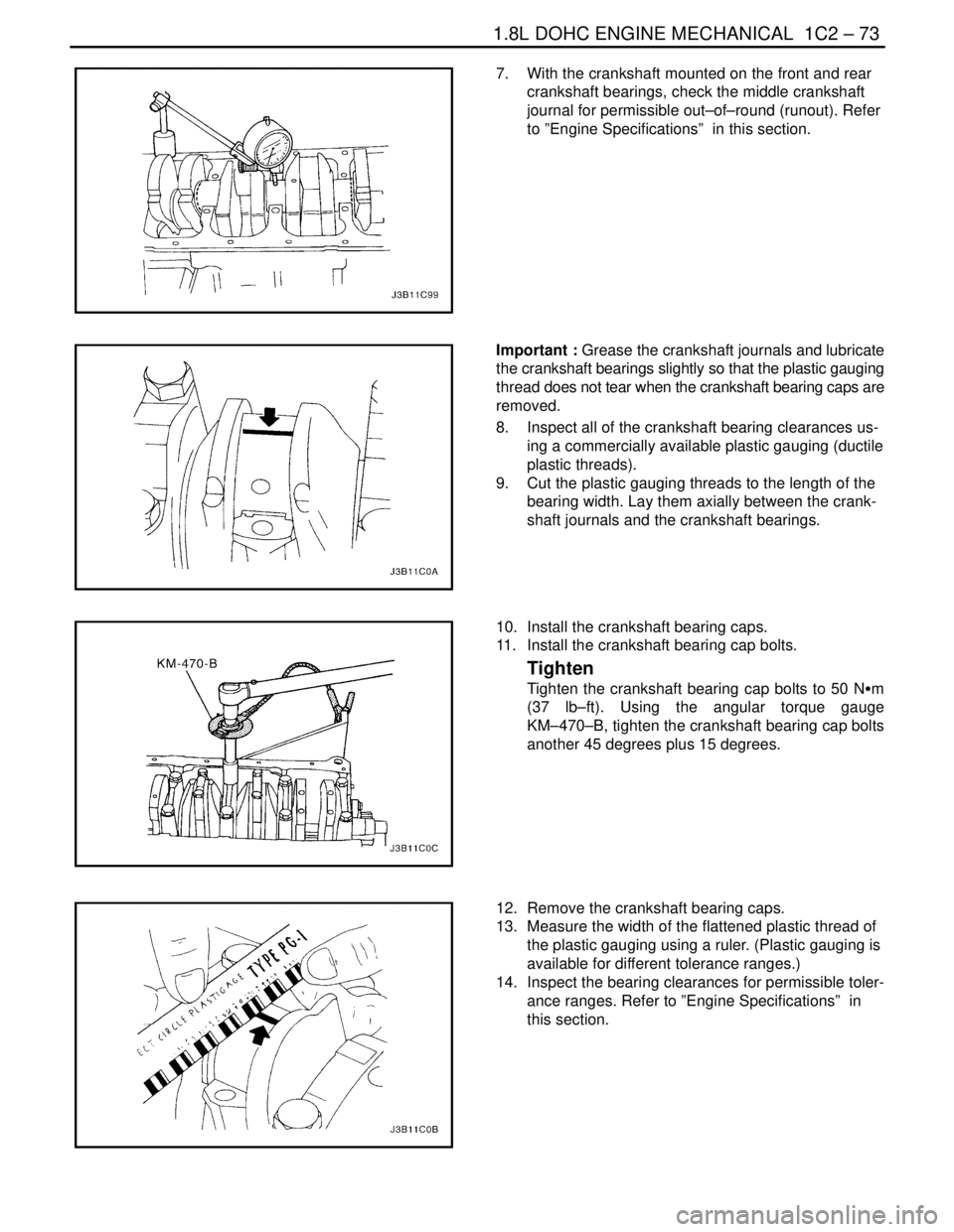
7. With the crankshaft mounted on the front and rear
crankshaft bearings, check the middle crankshaft
journal for permissible out–of–round (runout). Refer
to ”Engine Specifications” in this section.
Important : Grease the crankshaft journals and lubricate
the crankshaft bearings slightly so that the plastic gauging
thread does not tear when the crankshaft bearing caps are
removed.
8. Inspect all of the crankshaft bearing clearances us-
ing a commercially available plastic gauging (ductile
plastic threads).
9. Cut the plastic gauging threads to the length of the
bearing width. Lay them axially between the crank-
shaft journals and the crankshaft bearings.
10. Install the crankshaft bearing caps.
11. Install the crankshaft bearing cap bolts.
Tighten
Tighten the crankshaft bearing cap bolts to 50 NSm
(37 lb–ft). Using the angular torque gauge
KM–470–B, tighten the crankshaft bearing cap bolts
another 45 degrees plus 15 degrees.
12. Remove the crankshaft bearing caps.
13. Measure the width of the flattened plastic thread of
the plastic gauging using a ruler. (Plastic gauging is
available for different tolerance ranges.)
14. Inspect the bearing clearances for permissible toler-
ance ranges. Refer to ”Engine Specifications” in
this section.
Page 194 of 2643
1C2 – 74I1.8L DOHC ENGINE MECHANICAL
DAEWOO V–121 BL4
Inspection Procedure – Connecting Rods
1. Coat the connecting rod bearings with engine oil.
2. Install the upper connecting rod bearings into the
connecting rod journals.
3. Install the lower connecting rod bearings into the
connecting rod bearing caps.
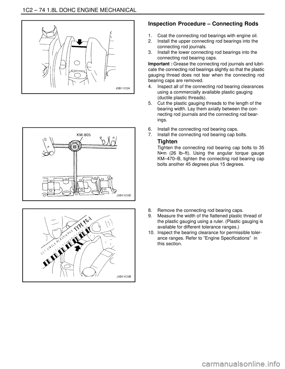
Important : Grease the connecting rod journals and lubri-
cate the connecting rod bearings slightly so that the plastic
gauging thread does not tear when the connecting rod
bearing caps are removed.
4. Inspect all of the connecting rod bearing clearances
using a commercially available plastic gauging
(ductile plastic threads).
5. Cut the plastic gauging threads to the length of the
bearing width. Lay them axially between the con-
necting rod journals and the connecting rod bear-
ings.
6. Install the connecting rod bearing caps.
7. Install the connecting rod bearing cap bolts.
Tighten
Tighten the connecting rod bearing cap bolts to 35
NSm (26 lb–ft). Using the angular torque gauge
KM–470–B, tighten the connecting rod bearing cap
bolts another 45 degrees plus 15 degrees.
8. Remove the connecting rod bearing caps.
9. Measure the width of the flattened plastic thread of
the plastic gauging using a ruler. (Plastic gauging is
available for different tolerance ranges.)
10. Inspect the bearing clearance for permissible toler-
ance ranges. Refer to ”Engine Specifications” in
this section.
Page 196 of 2643

SECTION : 1D
ENGINE COOLING
CAUTION : Disconnect the negative battery cable before removing or installing any electrical unit or when a tool
or equipment could easily come in contact with exposed electrical terminals. Disconnecting this cable will help
prevent personal injury and damage to the vehicle. The ignition must also be in LOCK unless otherwise noted.
TABLE OF CONTENTS
SPECIFICATIONS1D–2 . . . . . . . . . . . . . . . . . . . . . . . . . .
Capacity 1D–2. . . . . . . . . . . . . . . . . . . . . . . . . . . . . . . . . .
Fastener Tightening Specifications 1D–2. . . . . . . . . . .
SPECIAL TOOLS1D–2 . . . . . . . . . . . . . . . . . . . . . . . . . . .
Special Tools Table 1D–2. . . . . . . . . . . . . . . . . . . . . . . .
DIAGNOSIS1D–3 . . . . . . . . . . . . . . . . . . . . . . . . . . . . . . . .
Thermostat Test 1D–3. . . . . . . . . . . . . . . . . . . . . . . . . . .
Surge Tank Cap Test 1D–3. . . . . . . . . . . . . . . . . . . . . . .
Cooling System Diagnosis 1D–4. . . . . . . . . . . . . . . . . .
COMPONENT LOCATOR1D–5 . . . . . . . . . . . . . . . . . . . .
Radiator/Fan 1D–5. . . . . . . . . . . . . . . . . . . . . . . . . . . . . .
Water Pump/Thermostat (1.4L/1.6L DOHC) 1D–6. . .
Water Pump/Thermostat (1.8L DOHC) 1D–7. . . . . . .
MAINTENANCE AND REPAIR1D–8 . . . . . . . . . . . . . . .
ON–VEHICLE SERVICE 1D–8. . . . . . . . . . . . . . . . . . . . . Draining and Refilling the Cooling System 1D–8. . . . .
Thermostat (1.4L/1.6L DOHC) 1D–9. . . . . . . . . . . . . . .
Thermostat (1.8L DOHC) 1D–10. . . . . . . . . . . . . . . . . .
Water Pump 1D–11. . . . . . . . . . . . . . . . . . . . . . . . . . . . .
Electric Cooling Fan – Main or Auxiliary 1D–13. . . . . .
Surge Tank 1D–14. . . . . . . . . . . . . . . . . . . . . . . . . . . . . .
Radiator 1D–16. . . . . . . . . . . . . . . . . . . . . . . . . . . . . . . . .
GENERAL DESCRIPTION AND SYSTEM
OPERATION1D–18 . . . . . . . . . . . . . . . . . . . . . . . . . . . . .
General Description 1D–18. . . . . . . . . . . . . . . . . . . . . . .
Radiator 1D–18. . . . . . . . . . . . . . . . . . . . . . . . . . . . . . . . .
Surge Tank 1D–18. . . . . . . . . . . . . . . . . . . . . . . . . . . . . .
Water Pump 1D–18. . . . . . . . . . . . . . . . . . . . . . . . . . . . .
Thermostat 1D–18. . . . . . . . . . . . . . . . . . . . . . . . . . . . . .
Electric Cooling Fan 1D–19. . . . . . . . . . . . . . . . . . . . . . .
Engine Block Heater 1D–19. . . . . . . . . . . . . . . . . . . . . .
Page 198 of 2643
ENGINE COOLING 1D – 3
DAEWOO V–121 BL4
DIAGNOSIS
THERMOSTAT TEST
1. Remove the thermostat from the vehicle. Refer to
”Thermostat” in this section.
2. Make sure the valve spring is tight when the ther-
mostat is fully closed. If the spring is not tight, re-
place the thermostat.
3. Suspend the thermostat and a thermometer in a
pan of 50/50 mixture of ethylene glycol and water.
Do not let the thermostat or the thermometer rest
on the bottom of the pan because the uneven con-
centration of heat on the bottom could result in in-
accurate temperature measurements.
4. Heat the pan on a burner.
5. Use the thermometer to measure the temperature
of the heated solution.
6. The thermostat should begin to open at 87°C
(189°F) and it should be fully open at 102°C
(216°F). If it does not open at these temperatures,
replace the thermostat.
SURGE TANK CAP TEST
Tools Required
KM–471 Adapter
The surge tank cap maintains proper pressure, protects
the system from high pressure by opening a pressure
valve, and protects the coolant hoses from collapsing be-
cause of a vacuum.1. Wash any sludge from the surge tank cap and the
valve seat of the vacuum pressure valve for the
surge tank cap.
2. Check for any damage or deformity to the vacuum
pressure valve for the surge tank cap. If any dam-
age or deformity is found, replace the cap.
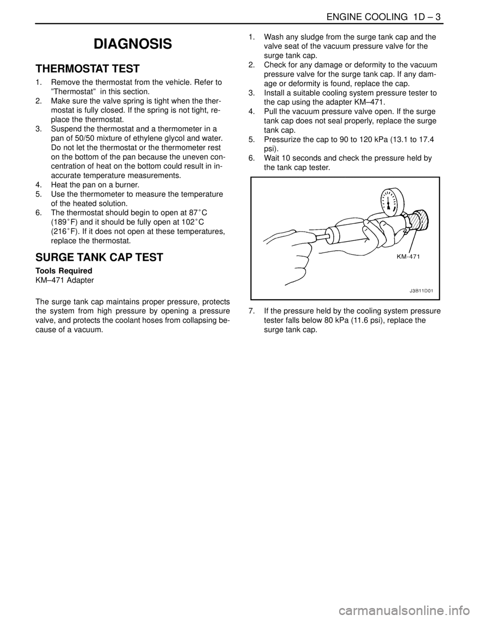
3. Install a suitable cooling system pressure tester to
the cap using the adapter KM–471.
4. Pull the vacuum pressure valve open. If the surge
tank cap does not seal properly, replace the surge
tank cap.
5. Pressurize the cap to 90 to 120 kPa (13.1 to 17.4
psi).
6. Wait 10 seconds and check the pressure held by
the tank cap tester.
7. If the pressure held by the cooling system pressure
tester falls below 80 kPa (11.6 psi), replace the
surge tank cap.
Page 203 of 2643
1D – 8IENGINE COOLING
DAEWOO V–121 BL4
MAINTENANCE AND REPAIR
ON–VEHICLE SERVICE
DRAINING AND REFILLING THE
COOLING SYSTEM
CAUTION : Do not remove the surge tank cap while
the engine and the radiator are hot. Scalding fluid and
steam may be blown out under pressure.
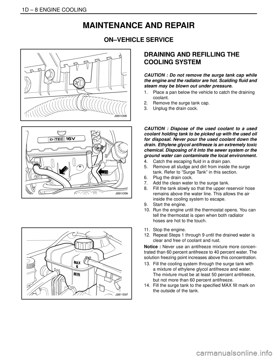
1. Place a pan below the vehicle to catch the draining
coolant.
2. Remove the surge tank cap.
3. Unplug the drain cock.
CAUTION : Dispose of the used coolant to a used
coolant holding tank to be picked up with the used oil
for disposal. Never pour the used coolant down the
drain. Ethylene glycol antifreeze is an extremely toxic
chemical. Disposing of it into the sewer system or the
ground water can contaminate the local environment.
4. Catch the escaping fluid in a drain pan.
5. Remove all sludge and dirt from inside the surge
tank. Refer to ”Surge Tank” in this section.
6. Plug the drain cock.
7. Add the clean water to the surge tank.
8. Fill the tank slowly so that the upper reservoir hose
remains above the water line. This allows the air
inside the cooling system to escape.
9. Start the engine.
10. Run the engine until the thermostat opens. You can
tell the thermostat is open when both radiator
hoses are hot to the touch.
11. Stop the engine.
12. Repeat Steps 1 through 9 until the drained water is
clear and free of coolant and rust.
Notice : Never use an antifreeze mixture more concen-
trated than 60 percent antifreeze to 40 percent water. The
solution freezing point increases above this concentration.
13. Fill the cooling system through the surge tank with
a mixture of ethylene glycol antifreeze and water.
The mixture must be at least 50 percent antifreeze,
but not more than 60 percent antifreeze.
14. Fill the surge tank to the specified MAX fill mark on
the outside of the tank.
Page 204 of 2643
ENGINE COOLING 1D – 9
DAEWOO V–121 BL4
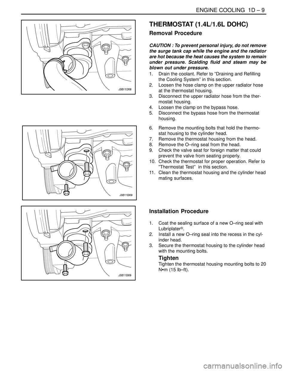
THERMOSTAT (1.4L/1.6L DOHC)
Removal Procedure
CAUTION : To prevent personal injury, do not remove
the surge tank cap while the engine and the radiator
are hot because the heat causes the system to remain
under pressure. Scalding fluid and steam may be
blown out under pressure.
1. Drain the coolant. Refer to ”Draining and Refilling
the Cooling System” in this section.
2. Loosen the hose clamp on the upper radiator hose
at the thermostat housing.
3. Disconnect the upper radiator hose from the ther-
mostat housing.
4. Loosen the clamp on the bypass hose.
5. Disconnect the bypass hose from the thermostat
housing.
6. Remove the mounting bolts that hold the thermo-
stat housing to the cylinder head.
7. Remove the thermostat housing from the head.
8. Remove the O–ring seal from the head.
9. Check the valve seat for foreign matter that could
prevent the valve from seating properly.
10. Check the thermostat for proper operation. Refer to
”Thermostat Test” in this section.
11. Clean the thermostat housing and the cylinder head
mating surfaces.
Installation Procedure
1. Coat the sealing surface of a new O–ring seal with
Lubriplater®.
2. Install a new O–ring seal into the recess in the cyl-
inder head.
3. Secure the thermostat housing to the cylinder head
with the mounting bolts.
Tighten
Tighten the thermostat housing mounting bolts to 20
NSm (15 lb–ft).
Page 205 of 2643
1D – 10IENGINE COOLING
DAEWOO V–121 BL4
4. Connect the upper radiator hose to the thermostat
housing.
5. Secure the upper radiator hose to the thermostat
housing with a hose clamp.
6. Connect the bypass hose to the thermostat hous-
ing.
7. Secure the bypass hose with a hose clamp.
8. Refill the engine cooling system. Refer to ”Draining
and Refilling the Cooling System” in this section.
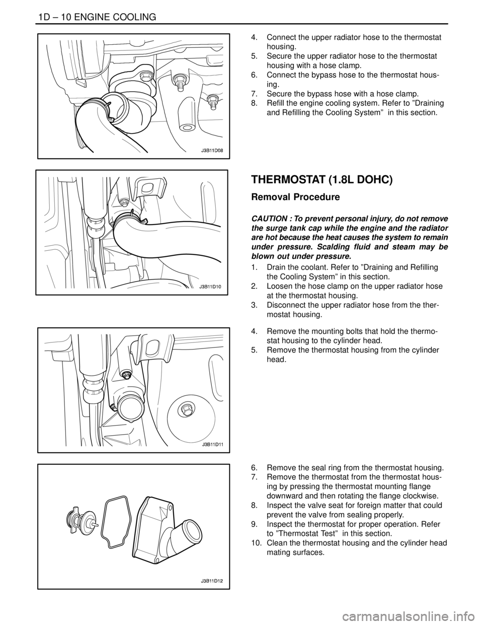
THERMOSTAT (1.8L DOHC)
Removal Procedure
CAUTION : To prevent personal injury, do not remove
the surge tank cap while the engine and the radiator
are hot because the heat causes the system to remain
under pressure. Scalding fluid and steam may be
blown out under pressure.
1. Drain the coolant. Refer to ”Draining and Refilling
the Cooling System” in this section.
2. Loosen the hose clamp on the upper radiator hose
at the thermostat housing.
3. Disconnect the upper radiator hose from the ther-
mostat housing.
4. Remove the mounting bolts that hold the thermo-
stat housing to the cylinder head.
5. Remove the thermostat housing from the cylinder
head.
6. Remove the seal ring from the thermostat housing.
7. Remove the thermostat from the thermostat hous-
ing by pressing the thermostat mounting flange
downward and then rotating the flange clockwise.
8. Inspect the valve seat for foreign matter that could
prevent the valve from sealing properly.
9. Inspect the thermostat for proper operation. Refer
to ”Thermostat Test” in this section.
10. Clean the thermostat housing and the cylinder head
mating surfaces.
Page 206 of 2643
ENGINE COOLING 1D – 11
DAEWOO V–121 BL4
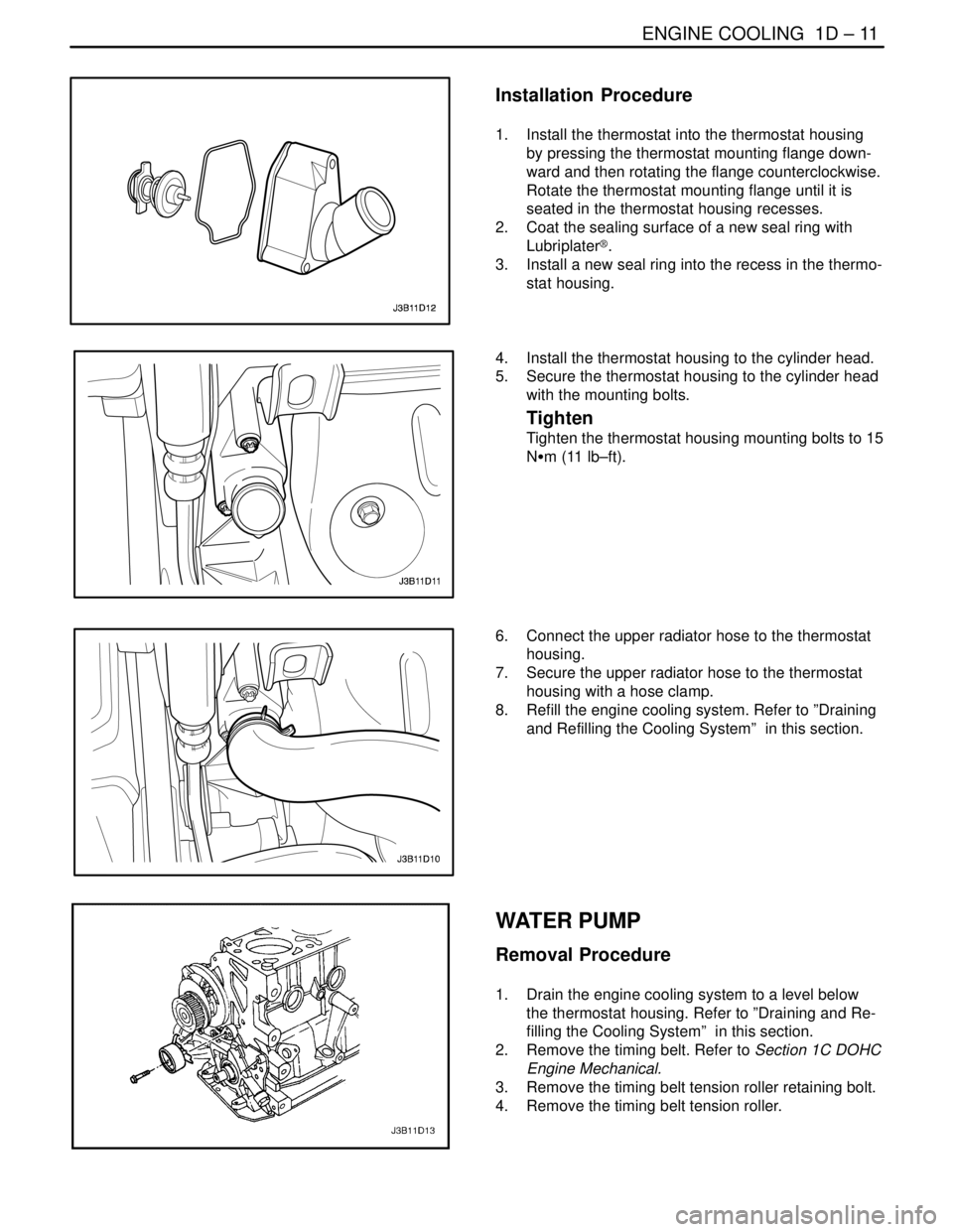
Installation Procedure
1. Install the thermostat into the thermostat housing
by pressing the thermostat mounting flange down-
ward and then rotating the flange counterclockwise.
Rotate the thermostat mounting flange until it is
seated in the thermostat housing recesses.
2. Coat the sealing surface of a new seal ring with
Lubriplater®.
3. Install a new seal ring into the recess in the thermo-
stat housing.
4. Install the thermostat housing to the cylinder head.
5. Secure the thermostat housing to the cylinder head
with the mounting bolts.
Tighten
Tighten the thermostat housing mounting bolts to 15
NSm (11 lb–ft).
6. Connect the upper radiator hose to the thermostat
housing.
7. Secure the upper radiator hose to the thermostat
housing with a hose clamp.
8. Refill the engine cooling system. Refer to ”Draining
and Refilling the Cooling System” in this section.
WATER PUMP
Removal Procedure
1. Drain the engine cooling system to a level below
the thermostat housing. Refer to ”Draining and Re-
filling the Cooling System” in this section.
2. Remove the timing belt. Refer to Section 1C DOHC
Engine Mechanical.
3. Remove the timing belt tension roller retaining bolt.
4. Remove the timing belt tension roller.