Page 175 of 2643
1.8L DOHC ENGINE MECHANICAL 1C2 – 55
DAEWOO V–121 BL4
20. Install the connecting rod cap bolts.
Tighten
Tighten the connecting rod bearing cap bolts to 35
NSm (26 lb–ft). Using the angular torque gauge
KM–470–B, tighten the bolts one turn of 45 degrees
plus one turn of 15 degrees.
21. Install the crankshaft bearing bridge/oil pan scraper
bolts.
Tighten
Tighten the crankshaft bearing bridge/oil pan scraper
bolts to 20 NSm (15 lb–ft) plus 45 degrees using the
angular torque gauge KM–470–B.
22. Install the oil suction pipe.
23. Install the oil suction pipe bolts.
Tighten
Tighten the oil suction pipe bolts to 8 NSm (71 lb–in)
and the oil suction pipe bracket bolt to 6 NSm (53 lb–
in).
24. Install the oil pan. Refer to ”Oil Pan” in this section.
25. Install the cylinder head with the intake manifold
and exhaust manifold attached. Refer to ”Cylinder
Head and Gasket” in this section.
Page 176 of 2643
1C2 – 56I1.8L DOHC ENGINE MECHANICAL
DAEWOO V–121 BL4
UNIT REPAIR
CYLINDER HEAD AND VALVE TRAIN
COMPONENTS
Tools Required
MKM–571–B Gauge
KM–340–0 Cutter Set
KM–340–7 Guide Drift
KM–340–13 Cutters
KM–340–26 Cutters
KM–348 Valve Spring Compressor
KM–653 Adapter
KM–805 Valve Guide Reamer
Disassembly Procedure
1. Remove the cylinder head with the intake manifold
and the exhaust manifold attached. Refer to ”Cylin-
der Head and Gasket” in this section.
2. Remove the exhaust manifold heat shield bolts.
3. Remove the exhaust manifold heat shield.
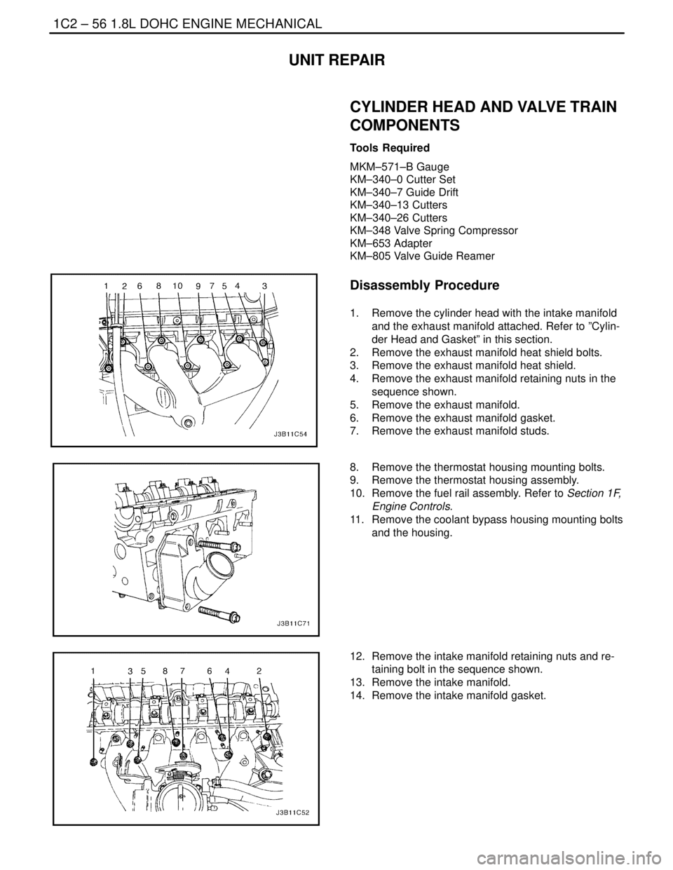
4. Remove the exhaust manifold retaining nuts in the
sequence shown.
5. Remove the exhaust manifold.
6. Remove the exhaust manifold gasket.
7. Remove the exhaust manifold studs.
8. Remove the thermostat housing mounting bolts.
9. Remove the thermostat housing assembly.
10. Remove the fuel rail assembly. Refer to Section 1F,
Engine Controls.
11. Remove the coolant bypass housing mounting bolts
and the housing.
12. Remove the intake manifold retaining nuts and re-
taining bolt in the sequence shown.
13. Remove the intake manifold.
14. Remove the intake manifold gasket.
Page 182 of 2643
1C2 – 62I1.8L DOHC ENGINE MECHANICAL
DAEWOO V–121 BL4
14. Install the intake camshaft.
15. Install the intake camshaft bearing caps in their
original positions.
16. Install the exhaust camshaft.
17. Install the exhaust camshaft bearing caps in their
original positions.
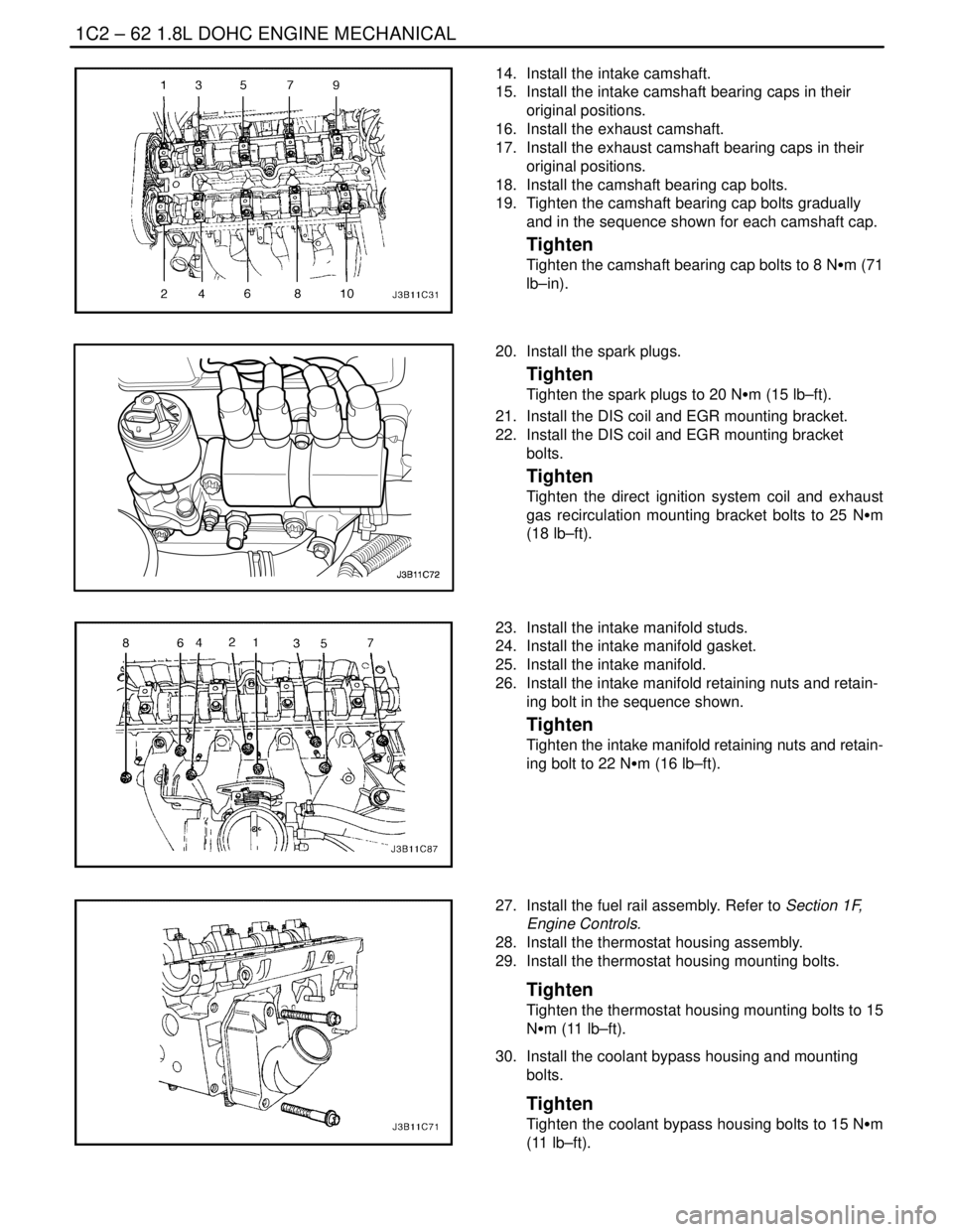
18. Install the camshaft bearing cap bolts.
19. Tighten the camshaft bearing cap bolts gradually
and in the sequence shown for each camshaft cap.
Tighten
Tighten the camshaft bearing cap bolts to 8 NSm (71
lb–in).
20. Install the spark plugs.
Tighten
Tighten the spark plugs to 20 NSm (15 lb–ft).
21. Install the DIS coil and EGR mounting bracket.
22. Install the DIS coil and EGR mounting bracket
bolts.
Tighten
Tighten the direct ignition system coil and exhaust
gas recirculation mounting bracket bolts to 25 NSm
(18 lb–ft).
23. Install the intake manifold studs.
24. Install the intake manifold gasket.
25. Install the intake manifold.
26. Install the intake manifold retaining nuts and retain-
ing bolt in the sequence shown.
Tighten
Tighten the intake manifold retaining nuts and retain-
ing bolt to 22 NSm (16 lb–ft).
27. Install the fuel rail assembly. Refer to Section 1F,
Engine Controls.
28. Install the thermostat housing assembly.
29. Install the thermostat housing mounting bolts.
Tighten
Tighten the thermostat housing mounting bolts to 15
NSm (11 lb–ft).
30. Install the coolant bypass housing and mounting
bolts.
Tighten
Tighten the coolant bypass housing bolts to 15 NSm
(11 lb–ft).
Page 183 of 2643
1.8L DOHC ENGINE MECHANICAL 1C2 – 63
DAEWOO V–121 BL4
31. Install the exhaust manifold studs.
32. Install the exhaust manifold gasket.
33. Install the exhaust manifold.
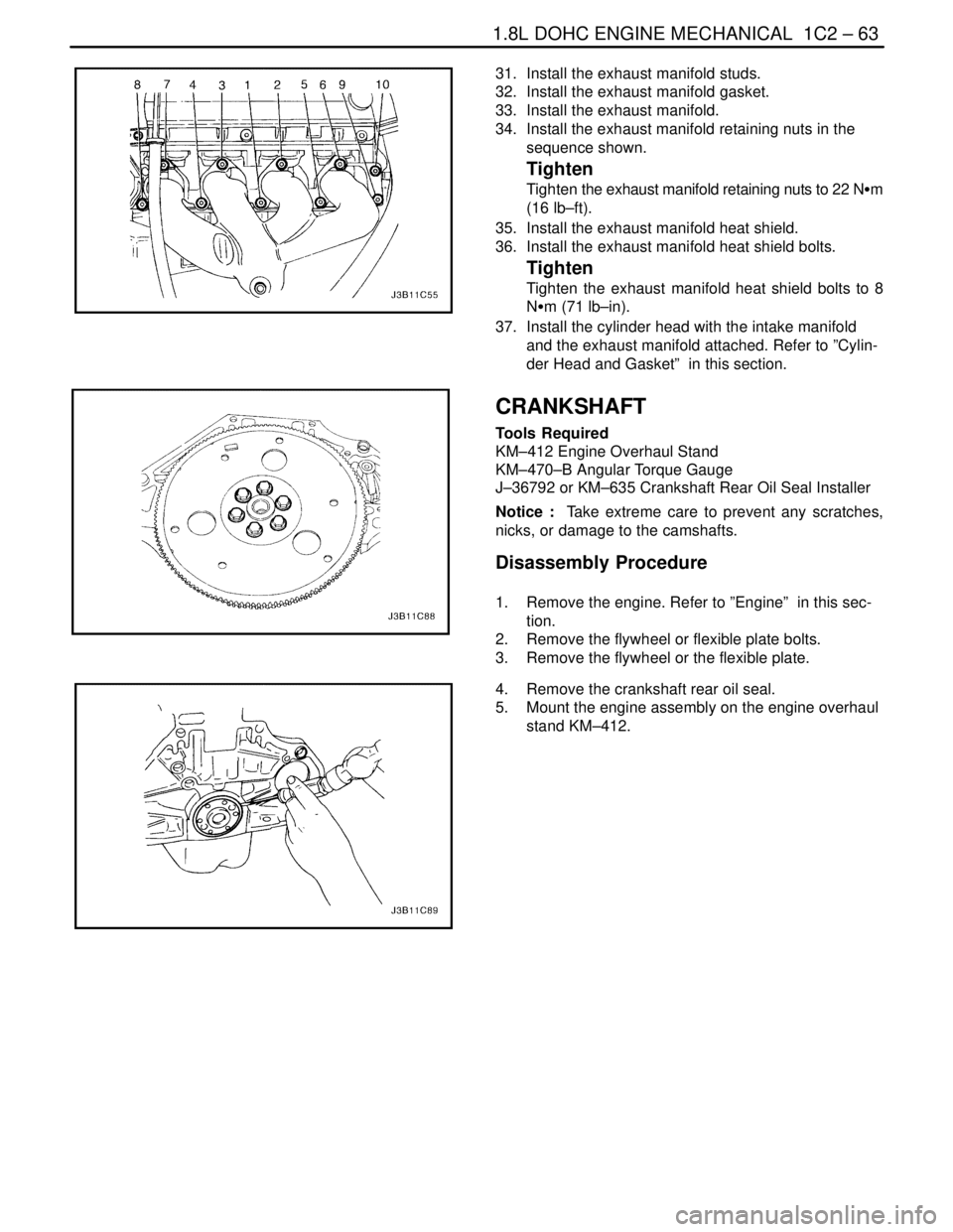
34. Install the exhaust manifold retaining nuts in the
sequence shown.
Tighten
Tighten the exhaust manifold retaining nuts to 22 NSm
(16 lb–ft).
35. Install the exhaust manifold heat shield.
36. Install the exhaust manifold heat shield bolts.
Tighten
Tighten the exhaust manifold heat shield bolts to 8
NSm (71 lb–in).
37. Install the cylinder head with the intake manifold
and the exhaust manifold attached. Refer to ”Cylin-
der Head and Gasket” in this section.
CRANKSHAFT
Tools Required
KM–412 Engine Overhaul Stand
KM–470–B Angular Torque Gauge
J–36792 or KM–635 Crankshaft Rear Oil Seal Installer
Notice : Take extreme care to prevent any scratches,
nicks, or damage to the camshafts.
Disassembly Procedure
1. Remove the engine. Refer to ”Engine” in this sec-
tion.
2. Remove the flywheel or flexible plate bolts.
3. Remove the flywheel or the flexible plate.
4. Remove the crankshaft rear oil seal.
5. Mount the engine assembly on the engine overhaul
stand KM–412.
Page 187 of 2643
1.8L DOHC ENGINE MECHANICAL 1C2 – 67
DAEWOO V–121 BL4
3. Install the crankshaft.
4. Install the lower crankshaft bearings in the bearing
caps.
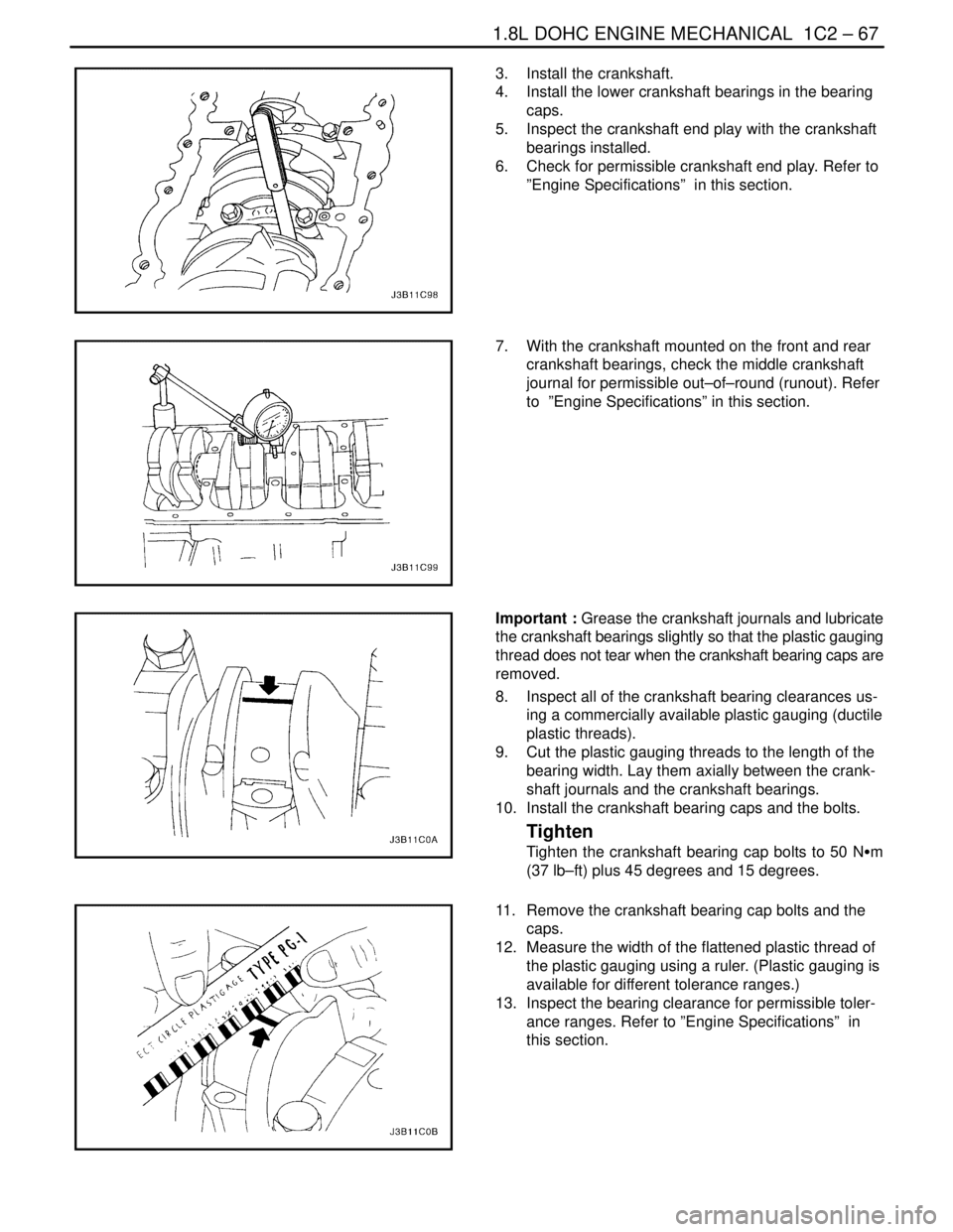
5. Inspect the crankshaft end play with the crankshaft
bearings installed.
6. Check for permissible crankshaft end play. Refer to
”Engine Specifications” in this section.
7. With the crankshaft mounted on the front and rear
crankshaft bearings, check the middle crankshaft
journal for permissible out–of–round (runout). Refer
to ”Engine Specifications” in this section.
Important : Grease the crankshaft journals and lubricate
the crankshaft bearings slightly so that the plastic gauging
thread does not tear when the crankshaft bearing caps are
removed.
8. Inspect all of the crankshaft bearing clearances us-
ing a commercially available plastic gauging (ductile
plastic threads).
9. Cut the plastic gauging threads to the length of the
bearing width. Lay them axially between the crank-
shaft journals and the crankshaft bearings.
10. Install the crankshaft bearing caps and the bolts.
Tighten
Tighten the crankshaft bearing cap bolts to 50 NSm
(37 lb–ft) plus 45 degrees and 15 degrees.
11. Remove the crankshaft bearing cap bolts and the
caps.
12. Measure the width of the flattened plastic thread of
the plastic gauging using a ruler. (Plastic gauging is
available for different tolerance ranges.)
13. Inspect the bearing clearance for permissible toler-
ance ranges. Refer to ”Engine Specifications” in
this section.
Page 188 of 2643
1C2 – 68I1.8L DOHC ENGINE MECHANICAL
DAEWOO V–121 BL4
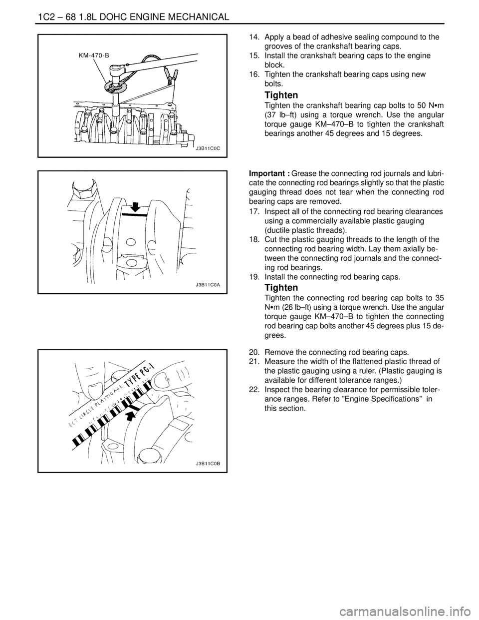
14. Apply a bead of adhesive sealing compound to the
grooves of the crankshaft bearing caps.
15. Install the crankshaft bearing caps to the engine
block.
16. Tighten the crankshaft bearing caps using new
bolts.
Tighten
Tighten the crankshaft bearing cap bolts to 50 NSm
(37 lb–ft) using a torque wrench. Use the angular
torque gauge KM–470–B to tighten the crankshaft
bearings another 45 degrees and 15 degrees.
Important : Grease the connecting rod journals and lubri-
cate the connecting rod bearings slightly so that the plastic
gauging thread does not tear when the connecting rod
bearing caps are removed.
17. Inspect all of the connecting rod bearing clearances
using a commercially available plastic gauging
(ductile plastic threads).
18. Cut the plastic gauging threads to the length of the
connecting rod bearing width. Lay them axially be-
tween the connecting rod journals and the connect-
ing rod bearings.
19. Install the connecting rod bearing caps.
Tighten
Tighten the connecting rod bearing cap bolts to 35
NSm (26 lb–ft) using a torque wrench. Use the angular
torque gauge KM–470–B to tighten the connecting
rod bearing cap bolts another 45 degrees plus 15 de-
grees.
20. Remove the connecting rod bearing caps.
21. Measure the width of the flattened plastic thread of
the plastic gauging using a ruler. (Plastic gauging is
available for different tolerance ranges.)
22. Inspect the bearing clearance for permissible toler-
ance ranges. Refer to ”Engine Specifications” in
this section.
Page 191 of 2643
1.8L DOHC ENGINE MECHANICAL 1C2 – 71
DAEWOO V–121 BL4
Notice : Take extreme care to prevent any scratches,
nicks or damage to the camshafts.
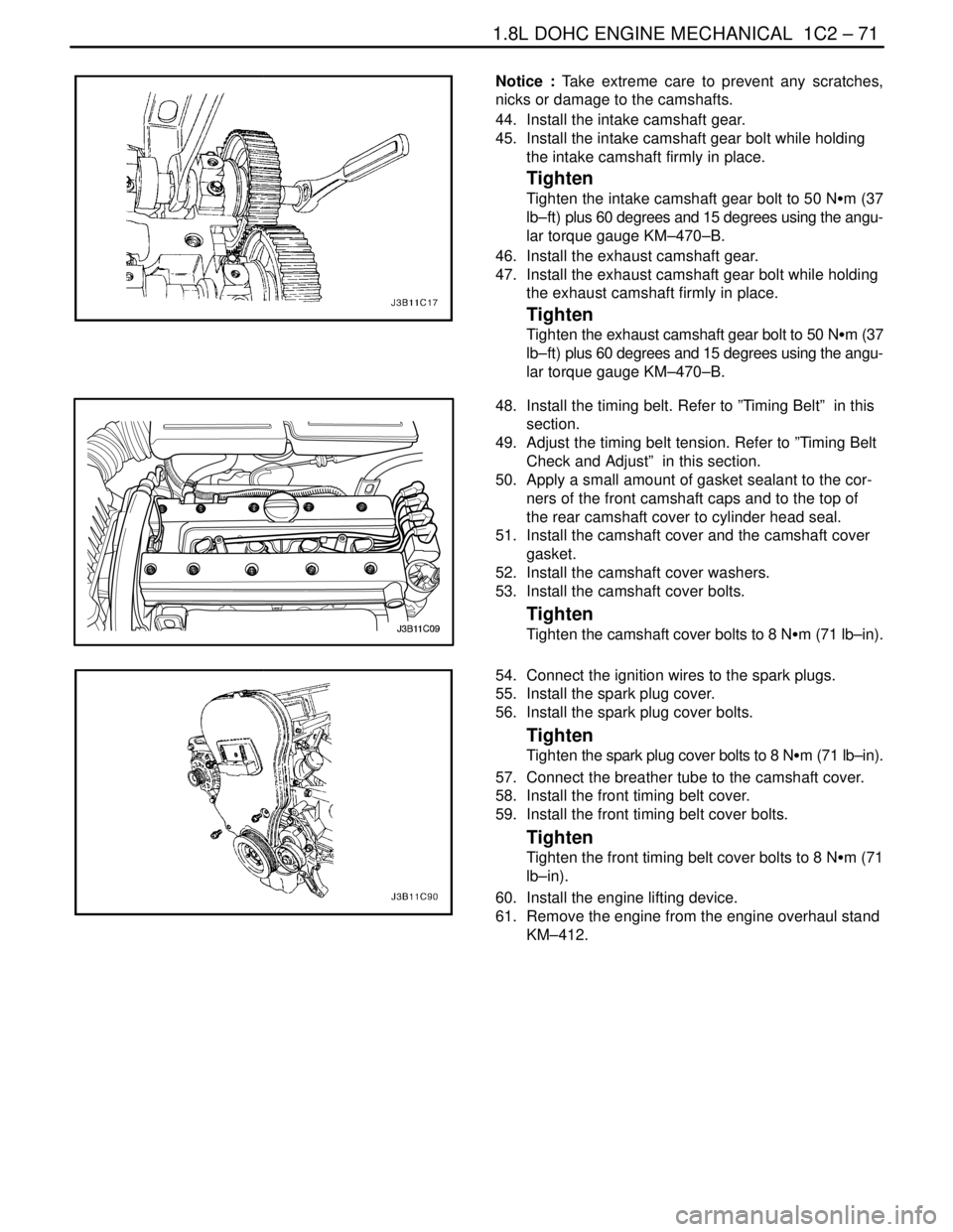
44. Install the intake camshaft gear.
45. Install the intake camshaft gear bolt while holding
the intake camshaft firmly in place.
Tighten
Tighten the intake camshaft gear bolt to 50 NSm (37
lb–ft) plus 60 degrees and 15 degrees using the angu-
lar torque gauge KM–470–B.
46. Install the exhaust camshaft gear.
47. Install the exhaust camshaft gear bolt while holding
the exhaust camshaft firmly in place.
Tighten
Tighten the exhaust camshaft gear bolt to 50 NSm (37
lb–ft) plus 60 degrees and 15 degrees using the angu-
lar torque gauge KM–470–B.
48. Install the timing belt. Refer to ”Timing Belt” in this
section.
49. Adjust the timing belt tension. Refer to ”Timing Belt
Check and Adjust” in this section.
50. Apply a small amount of gasket sealant to the cor-
ners of the front camshaft caps and to the top of
the rear camshaft cover to cylinder head seal.
51. Install the camshaft cover and the camshaft cover
gasket.
52. Install the camshaft cover washers.
53. Install the camshaft cover bolts.
Tighten
Tighten the camshaft cover bolts to 8 NSm (71 lb–in).
54. Connect the ignition wires to the spark plugs.
55. Install the spark plug cover.
56. Install the spark plug cover bolts.
Tighten
Tighten the spark plug cover bolts to 8 NSm (71 lb–in).
57. Connect the breather tube to the camshaft cover.
58. Install the front timing belt cover.
59. Install the front timing belt cover bolts.
Tighten
Tighten the front timing belt cover bolts to 8 NSm (71
lb–in).
60. Install the engine lifting device.
61. Remove the engine from the engine overhaul stand
KM–412.
Page 192 of 2643

1C2 – 72I1.8L DOHC ENGINE MECHANICAL
DAEWOO V–121 BL4
62. Install a new crankshaft rear oil seal using installer
J–36792 or KM–635.
63. Install the flywheel or flexible plate.
64. Install the flywheel or the flexible plate bolts.
Tighten
Tighten the flywheel bolts to 65 NSm (48 lb–ft). Use
the angular torque gauge KM–470–B to tighten the
flywheel bolts another 30 degrees plus 15 degrees.
For the automatic transmission, tighten the flexible
plate bolts to 45 NSm (33 lb–ft).
65. Install the engine. Refer to ”Engine” in this section.
CRANKSHAFT BEARINGS AND
CONNECTING ROD BEARINGS –
GAUGING PLASTIC
Tools Required
KM–470–B Angular Torque Gauge
Inspection Procedure – Crankshaft
1. Coat the crankshaft bearings with engine oil.
2. Install the upper crankshaft bearings into the engine
block crankshaft journals.
3. Install the lower crankshaft bearings into the crank-
shaft bearing caps.
4. Install the crankshaft.
5. Inspect the crankshaft end play with the crankshaft
bearings installed.
6. Check for permissible crankshaft end play. Refer to
”Engine Specifications” in this section.