2004 DAEWOO LACETTI remove seats
[x] Cancel search: remove seatsPage 103 of 2643
1C1 – 60I1.4L/1.6L DOHC ENGINE MECHANICAL
DAEWOO V–121 BL4
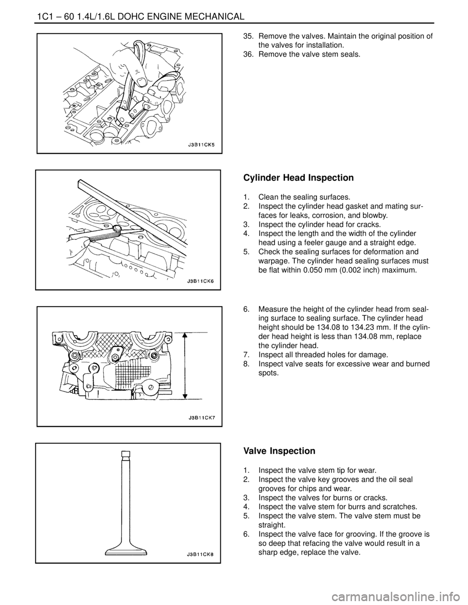
35. Remove the valves. Maintain the original position of
the valves for installation.
36. Remove the valve stem seals.
Cylinder Head Inspection
1. Clean the sealing surfaces.
2. Inspect the cylinder head gasket and mating sur-
faces for leaks, corrosion, and blowby.
3. Inspect the cylinder head for cracks.
4. Inspect the length and the width of the cylinder
head using a feeler gauge and a straight edge.
5. Check the sealing surfaces for deformation and
warpage. The cylinder head sealing surfaces must
be flat within 0.050 mm (0.002 inch) maximum.
6. Measure the height of the cylinder head from seal-
ing surface to sealing surface. The cylinder head
height should be 134.08 to 134.23 mm. If the cylin-
der head height is less than 134.08 mm, replace
the cylinder head.
7. Inspect all threaded holes for damage.
8. Inspect valve seats for excessive wear and burned
spots.
Valve Inspection
1. Inspect the valve stem tip for wear.
2. Inspect the valve key grooves and the oil seal
grooves for chips and wear.
3. Inspect the valves for burns or cracks.
4. Inspect the valve stem for burrs and scratches.
5. Inspect the valve stem. The valve stem must be
straight.
6. Inspect the valve face for grooving. If the groove is
so deep that refacing the valve would result in a
sharp edge, replace the valve.
Page 143 of 2643
1.8L DOHC ENGINE MECHANICAL 1C2 – 23
DAEWOO V–121 BL4
14. Loosen the camshaft bearing cap bolts in stages of
one–half to one turn.
15. Remove the camshaft bearing cap bolts from the
cylinder head.
16. Remove the camshafts.
17. Remove the seal ring from the camshafts.
Important : The camshaft must detach evenly from the
bearing seats in the front guide bearing.
18. Check the camshaft and bearing seats for wear and
replace them if necessary.
Installation Procedure
Notice : Take extreme care to prevent any scratches,
nicks or damage to the camshafts.
1. Lubricate the camshaft journals and the camshaft
caps with engine oil.
2. Install the intake camshaft.
3. Install the intake camshaft caps in their original
positions.
4. Install the intake camshaft cap bolts.
5. Install the exhaust camshaft.
6. Install the exhaust camshaft caps in their original
positions.
7. Install the exhaust camshaft cap bolts.
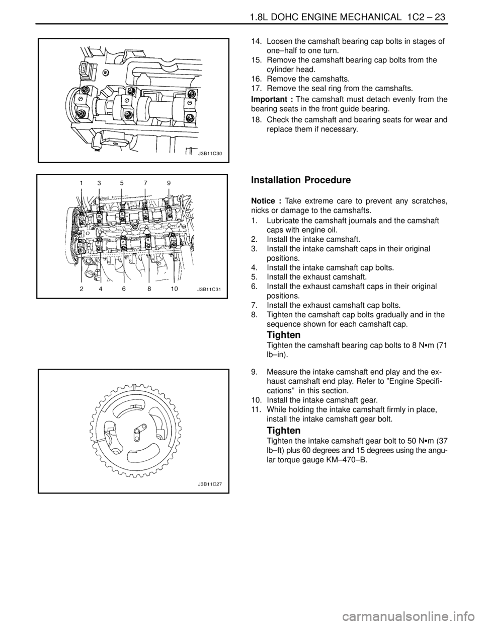
8. Tighten the camshaft cap bolts gradually and in the
sequence shown for each camshaft cap.
Tighten
Tighten the camshaft bearing cap bolts to 8 NSm (71
lb–in).
9. Measure the intake camshaft end play and the ex-
haust camshaft end play. Refer to ”Engine Specifi-
cations” in this section.
10. Install the intake camshaft gear.
11. While holding the intake camshaft firmly in place,
install the intake camshaft gear bolt.
Tighten
Tighten the intake camshaft gear bolt to 50 NSm (37
lb–ft) plus 60 degrees and 15 degrees using the angu-
lar torque gauge KM–470–B.
Page 178 of 2643
1C2 – 58I1.8L DOHC ENGINE MECHANICAL
DAEWOO V–121 BL4
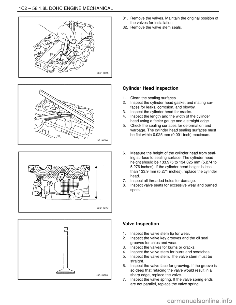
31. Remove the valves. Maintain the original position of
the valves for installation.
32. Remove the valve stem seals.
Cylinder Head Inspection
1. Clean the sealing surfaces.
2. Inspect the cylinder head gasket and mating sur-
faces for leaks, corrosion, and blowby.
3. Inspect the cylinder head for cracks.
4. Inspect the length and the width of the cylinder
head using a feeler gauge and a straight edge.
5. Check the sealing surfaces for deformation and
warpage. The cylinder head sealing surfaces must
be flat within 0.025 mm (0.001 inch) maximum.
6. Measure the height of the cylinder head from seal-
ing surface to sealing surface. The cylinder head
height should be 133.975 to 134.025 mm (5.274 to
5.276 inches). If the cylinder head height is less
than 133.9 mm (5.271 inches), replace the cylinder
head.
7. Inspect all threaded holes for damage.
8. Inspect valve seats for excessive wear and burned
spots.
Valve Inspection
1. Inspect the valve stem tip for wear.
2. Inspect the valve key grooves and the oil seal
grooves for chips and wear.
3. Inspect the valves for burns or cracks.
4. Inspect the valve stem for burrs and scratches.
5. Inspect the valve stem. The valve stem must be
straight.
6. Inspect the valve face for grooving. If the groove is
so deep that refacing the valve would result in a
sharp edge, replace the valve.
7. Inspect the valve spring. If the valve spring ends
are not parallel, replace the valve spring.
Page 181 of 2643
1.8L DOHC ENGINE MECHANICAL 1C2 – 61
DAEWOO V–121 BL4
4. Inspect the dimension for the valve seat width.
S Intake: 1.2 to 1.4 mm (0.047 to 0.055 inch).
S Exhaust: 1.4 to 1.8 mm (0.055 to 0.070 inch).
5. Inspect the assembly height of the intake valves
and the exhaust valves. If the dimension is exceed-
ed, install new valves. Inspect the assembly height
of the intake valves and the exhaust valves again. If
the valve assembly height is still too large despite
replacing the valves, replace the cylinder head.
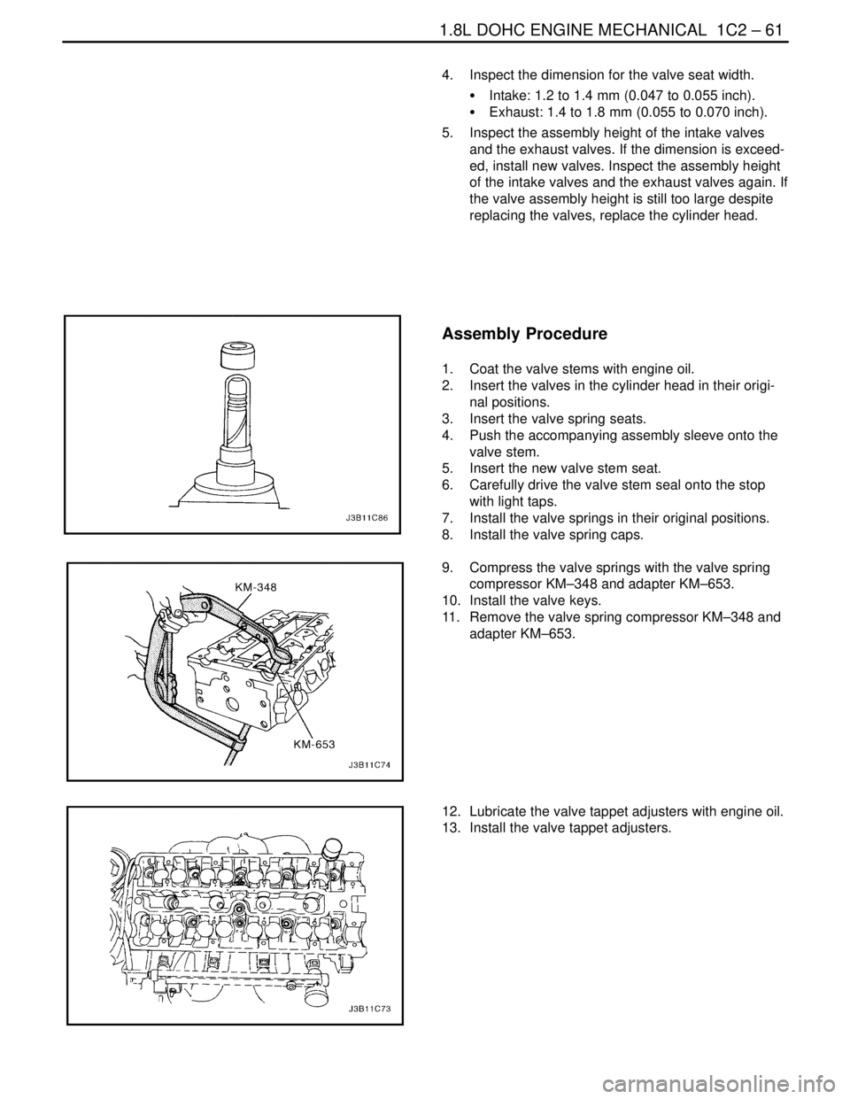
Assembly Procedure
1. Coat the valve stems with engine oil.
2. Insert the valves in the cylinder head in their origi-
nal positions.
3. Insert the valve spring seats.
4. Push the accompanying assembly sleeve onto the
valve stem.
5. Insert the new valve stem seat.
6. Carefully drive the valve stem seal onto the stop
with light taps.
7. Install the valve springs in their original positions.
8. Install the valve spring caps.
9. Compress the valve springs with the valve spring
compressor KM–348 and adapter KM–653.
10. Install the valve keys.
11. Remove the valve spring compressor KM–348 and
adapter KM–653.
12. Lubricate the valve tappet adjusters with engine oil.
13. Install the valve tappet adjusters.
Page 842 of 2643
1F – 596IENGINE CONTROLS
DAEWOO V–121 BL4
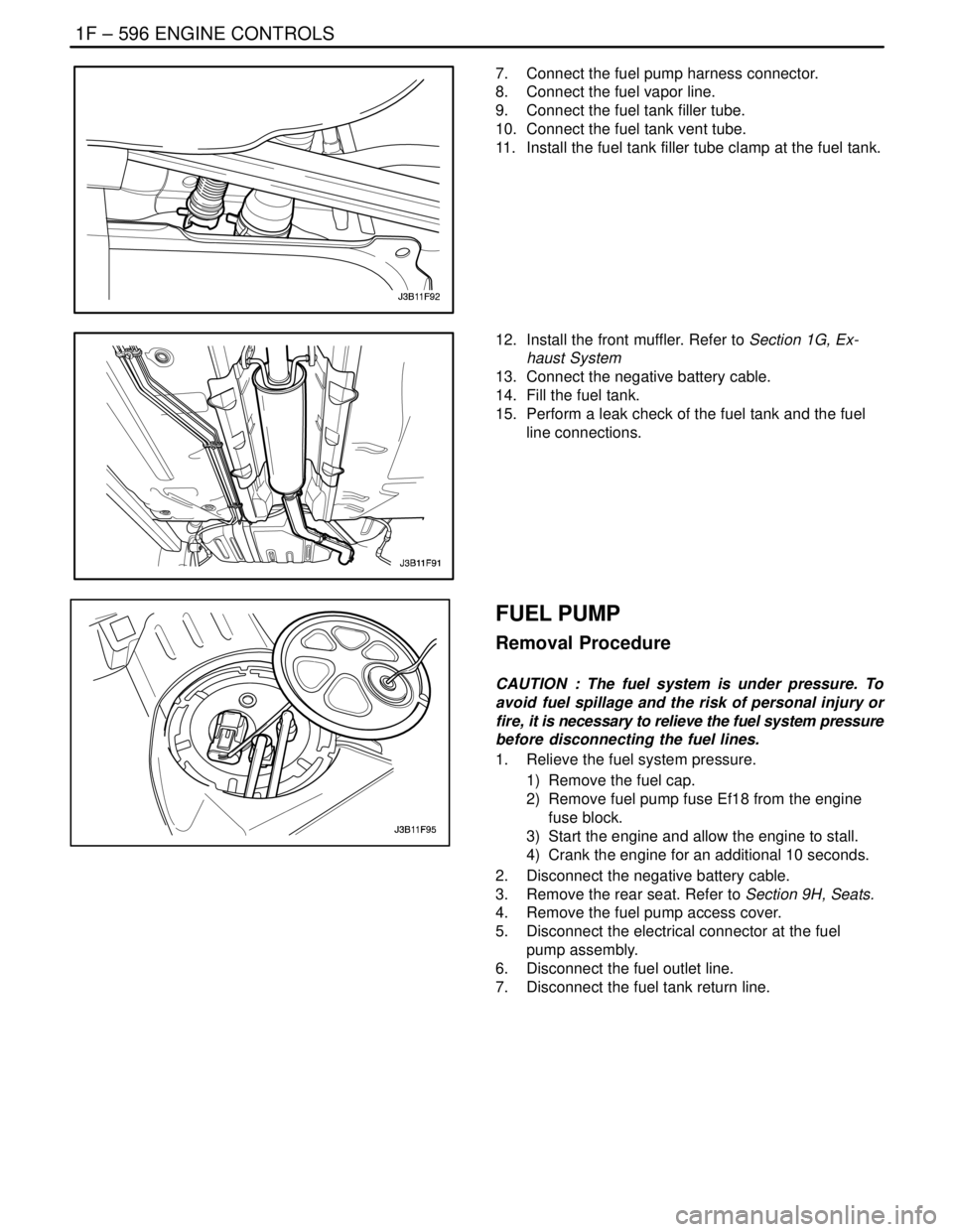
7. Connect the fuel pump harness connector.
8. Connect the fuel vapor line.
9. Connect the fuel tank filler tube.
10. Connect the fuel tank vent tube.
11. Install the fuel tank filler tube clamp at the fuel tank.
12. Install the front muffler. Refer to Section 1G, Ex-
haust System
13. Connect the negative battery cable.
14. Fill the fuel tank.
15. Perform a leak check of the fuel tank and the fuel
line connections.
FUEL PUMP
Removal Procedure
CAUTION : The fuel system is under pressure. To
avoid fuel spillage and the risk of personal injury or
fire, it is necessary to relieve the fuel system pressure
before disconnecting the fuel lines.
1. Relieve the fuel system pressure.
1) Remove the fuel cap.
2) Remove fuel pump fuse Ef18 from the engine
fuse block.
3) Start the engine and allow the engine to stall.
4) Crank the engine for an additional 10 seconds.
2. Disconnect the negative battery cable.
3. Remove the rear seat. Refer to Section 9H, Seats.
4. Remove the fuel pump access cover.
5. Disconnect the electrical connector at the fuel
pump assembly.
6. Disconnect the fuel outlet line.
7. Disconnect the fuel tank return line.
Page 843 of 2643

ENGINE CONTROLS 1F – 597
DAEWOO V–121 BL4
8. Turn the lock ring counterclockwise to clear the
tank tabs.
9. Remove the fuel pump assembly from the tank.
Installation Procedure
1. Clean the gasket mating surface on the fuel tank.
2. Position the new gasket in place.
3. Install the fuel pump into the fuel tank in the same
location as removed for ease of line and connector
installation.
4. Position the lock ring in place and turn it clockwise
until it contacts the tank stop.
5. Connect the fuel pump assembly connector.
6. Install the fuel pump outlet line.
7. Install the fuel tank return line.
8. Install the fuel pump access cover.
9. Connect the negative battery cable.
10. Perform an operational check of the fuel pump.
11. Install the rear seat. Refer to Section 9H, Seats.
FUEL FILTER
Removal Procedure
CAUTION : The fuel system is under pressure. To
avoid fuel spillage and the risk of personal injury or
fire, it is necessary to relieve the fuel system pressure
before disconnecting the fuel lines.
1. Relieve the fuel system pressure. Refer to ” Fuel
System Pressure Relief ” in this section.
2. Disconnect the negative battery cable.
3. Remove the fuel filter mounting bracket assembly
bolt.
4. Remove the fuel filter cover.
5. Disconnect the inlet/outlet fuel lines by moving the
line connector lock forward and pulling the hose off
of the fuel filter tube.
Page 970 of 2643
2E – 8ITIRES AND WHEELS
DAEWOO V–121 BL4
TIRE AND WHEEL
MATCH–MOUNTING
The tires and wheels are match–mounted at the assembly
plant. Match–mounting aligns the radially stiffest part of
the tire, or high spot, to the smallest radius, or low spot, of
the wheel.
The high spot of the tire is originally marked by a red paint
mark or an adhesive label on the outboard sidewall.
The low spot of the wheel will be at the location of the valve
stem.
Before dismounting a tire from its wheel, scribe a line on
the tire at the valve stem to assure that it is remounted in
the same position.
Replacement tires that are of original equipment quality
will have their high and low spot marked in the same man-
ner.
TIRE MOUNTING AND DISMOUNTING
Notice : Use a tire–changing machine to mount or dis-
mount the tires. Follow the equipment manufacturer’s in-
structions. Do not use hand tools or tire irons to change
tires. These tools may damage the beads or the wheel rim.
1. Clean the rim bead seats with a wire brush or
coarse steel wool to remove lubricants, old rubber,
and light rust. Before mounting or dismounting a
tire, lubricate the bead area well with an approved
tire lubricant.
CAUTION : To avoid serious injury, do not stand over
the tire when inflating it, because the bead may break
when it snaps over the safety hump. Do not exceed
275 kPa (40 psi) of air pressure in any tire if the beads
are not seated. If 275 kPa (40 psi) of air pressure will
not seat the beads, deflate the tire. Relubricate the
bead and reinflate the tire. Overinflation may cause
the bead to break and cause serious injury.
2. fter mounting the tire, inflate it until the beads are
seated. Never exceed 275 kPa (40 psi) to seat the
beads.
3. Install the valve core and inflate the tire to the prop-
er pressure. Make sure the locating ring outside of
the bead of the tire shows around the rim flanges of
the wheel on both sides. This positioning of the tire
will insure that the bead of the tire is seated.
Page 1579 of 2643
5A1 – 230IZF 4 HP 16 AUTOMATIC TRANSAXLE
DAEWOO V–121 BL4
4. Dismantle the oil pump gear, ring gear
5. Installation should follow the removal procedure in
the reverse order.
DIFFERENTIAL/SIDE SHAFT OUTER
RACE, BEARING SHIM
Disassembly and Assembly Procedure
1. Take out the outer race of the transaxle housing
side.
2. Remove the bearing shim.
3. Take out the outer race of the torque converter
housing side.
Installation Notice
S Heat the bearing seats well and insert bearing outer
rings with shim for differential and side shaft into
the transaxle housing.
IMPORTANT
MEASUREMENT/ADJUSTMENT
Tools Required
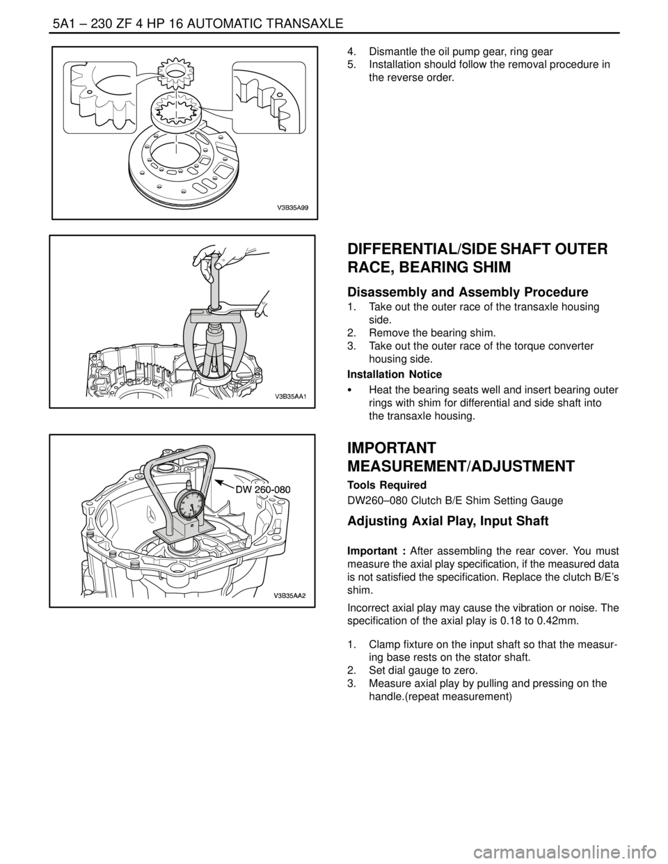
DW260–080 Clutch B/E Shim Setting Gauge
Adjusting Axial Play, Input Shaft
Important : After assembling the rear cover. You must
measure the axial play specification, if the measured data
is not satisfied the specification. Replace the clutch B/E’s
shim.
Incorrect axial play may cause the vibration or noise. The
specification of the axial play is 0.18 to 0.42mm.
1. Clamp fixture on the input shaft so that the measur-
ing base rests on the stator shaft.
2. Set dial gauge to zero.
3. Measure axial play by pulling and pressing on the
handle.(repeat measurement)