2004 DAEWOO LACETTI remove seats
[x] Cancel search: remove seatsPage 2458 of 2643
ROOF 9Q – 9
DAEWOO V–121 BL4
6. Remove the power sunroof control switch, if
equipped. Refer to ”Power Sunroof Control Switch”
in this section.
7. Remove the A–, B–, and C–pillar trim panels. Refer
to Section 9G, Interior Trim.
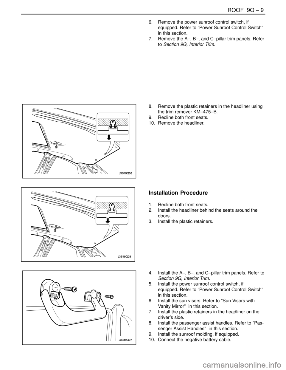
8. Remove the plastic retainers in the headliner using
the trim remover KM–475–B.
9. Recline both front seats.
10. Remove the headliner.
Installation Procedure
1. Recline both front seats.
2. Install the headliner behind the seats around the
doors.
3. Install the plastic retainers.
4. Install the A–, B–, and C–pillar trim panels. Refer to
Section 9G, Interior Trim.
5. Install the power sunroof control switch, if
equipped. Refer to ”Power Sunroof Control Switch”
in this section.
6. Install the sun visors. Refer to ”Sun Visors with
Vanity Mirror” in this section.
7. Install the plastic retainers in the headliner on the
driver’s side.
8. Install the passenger assist handles. Refer to ”Pas-
senger Assist Handles” in this section.
9. Install the sunroof molding, if equipped.
10. Connect the negative battery cable.
Page 2474 of 2643
BODY REAR END 9S – 3
DAEWOO V–121 BL4
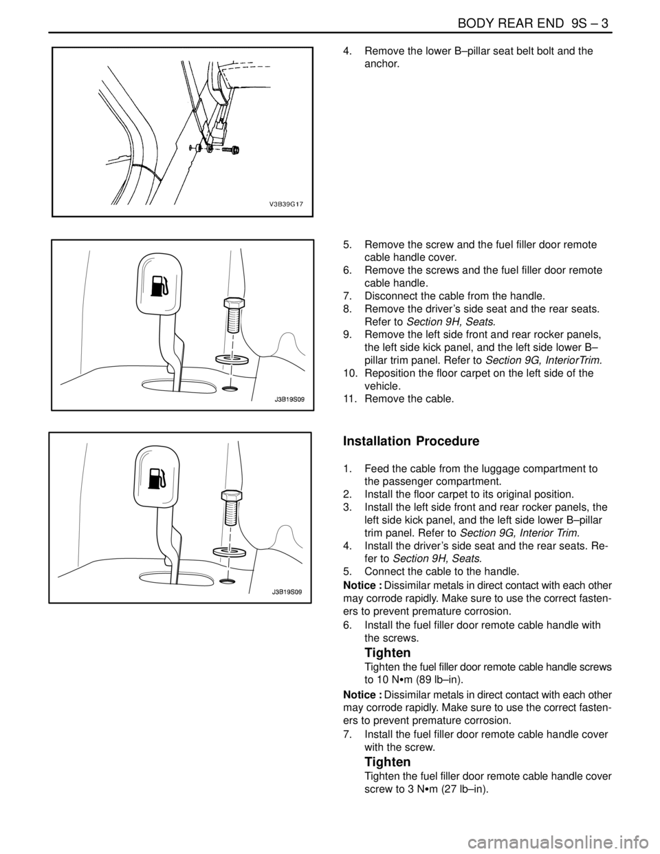
4. Remove the lower B–pillar seat belt bolt and the
anchor.
5. Remove the screw and the fuel filler door remote
cable handle cover.
6. Remove the screws and the fuel filler door remote
cable handle.
7. Disconnect the cable from the handle.
8. Remove the driver’s side seat and the rear seats.
Refer to Section 9H, Seats.
9. Remove the left side front and rear rocker panels,
the left side kick panel, and the left side lower B–
pillar trim panel. Refer to Section 9G, InteriorTrim.
10. Reposition the floor carpet on the left side of the
vehicle.
11. Remove the cable.
Installation Procedure
1. Feed the cable from the luggage compartment to
the passenger compartment.
2. Install the floor carpet to its original position.
3. Install the left side front and rear rocker panels, the
left side kick panel, and the left side lower B–pillar
trim panel. Refer to Section 9G, Interior Trim.
4. Install the driver’s side seat and the rear seats. Re-
fer to Section 9H, Seats.
5. Connect the cable to the handle.
Notice : Dissimilar metals in direct contact with each other
may corrode rapidly. Make sure to use the correct fasten-
ers to prevent premature corrosion.
6. Install the fuel filler door remote cable handle with
the screws.
Tighten
Tighten the fuel filler door remote cable handle screws
to 10 NSm (89 lb–in).
Notice : Dissimilar metals in direct contact with each other
may corrode rapidly. Make sure to use the correct fasten-
ers to prevent premature corrosion.
7. Install the fuel filler door remote cable handle cover
with the screw.
Tighten
Tighten the fuel filler door remote cable handle cover
screw to 3 NSm (27 lb–in).
Page 2510 of 2643
1–2 GENERAL INFORMATIONNUBIRA/LACETTI
1. GENERAL INSTRUCTION
This publication is designed to help you the body repair
technician with your specialized work. Vehicle bodywork
has changed a great deal over the years. As vehicles
have developed technically, vehicle bodywork has also
had to meet new requirements with design, changes to
reconcile apparently conflicting demands to name just a
few examples:
S strength and safety ; low weight
S spaciousness ; good aerodynamices
S high quality ; low price
.
The durability and ease of repair of the bodywork also
plays an important part.
.
Nowadays, the use of highly automated production
equipment makes it possible to maintain the tightest
tolerances and thus ensure a high level of quality.
.
When bodywork is damaged, the customer rightly ex-
pects it to be expertly repaired to the same quality stan-
dards.
.
At the same time, for his safety, the customer expects
you to have comprehensive knowledge of materials,
measuring and straightening methods, possible distor-
tion, optimum corrosion prevention and much more be-
sides.
.
This publication is designed to help you update your
knowledge and give you an idea of what you require to
rectify moderate or severe accident damage, for your
own safety and for the satisfaction of your customers.
2. IMPORTANT SAFETY NOTICE
2–1. BEFORE BEGINNING WORK
S Disconnect the battery to reduce the possibility of fire
caused by electrical shorts.
S Check for fuel leaks and repair as necessary.
S Remove the fuel tank and/or fuel lines if welding equip-
ment is to be used near the fuel system.
S Before welding, sanding or cutting, protect carpets and
seats with fire–proof covers.
S Follow standard safety practices when using toxic or
flammable liquids.
S Use standard safety equipment when spraying paint,
welding, cutting, sanding or grinding. Standard safety
equipment includes.
S Respirator and filter masks: Designed to filter out toxic
fumes, mist, dust or other airborn particles. Use a respi-
rator or filter mask designed to protect you from the haz-
ards of the particular job; some respirators, for example,
are designed to filter out only dust and airborn particles,
not toxic fumes.
S Safety goggles or glasses: Designed to protect your
eyes from projectiles, dust particles or splashing liquid.
S Gloves: Rubber gloves protect against corrosive chemi-
cals. Welding gloves protect against burns and abra-
sions caused by welding, sanding or grinding.
S Safety shoes: Non–slip soles protect against slipping.
Metal toe inserts protect against falling objects.
S Ear plugs: Protect eardrums from harmful noise levels.
.
2–2. DURING WORK
S Do not smoke while working near the fuel system.
S Deposit gas or solvent–soaked shop towels in an ap-
proved container.
S Brake lining contains asbestos, which can cause cancer.
Do not use an air hose to blow off brake assemblies: use
only an approved vacuum cleaner, and wear an ap-
proved filter mask or respirator.
S Always attach a safety cable when using a hydraulic ram
or a frame straightening table: do not stand in direct line
with the chains used on such equipment.
Page 2555 of 2643
NUBIRA/LACETTI ROOF, BACK PANEL AND REAR FLOOR PANEL 5–3
1–2. REPAIR PROCEDURE
1. Remove the related parts.
S Room lamp, door weatherstrip and pillar trims.
S Headlining and wiring harness.
S Wiper, cowl and windshield.
S Rear glass and others.
2. Pull out and straighten the damaged area to approxi-
mately the original shape.
Note : Use heat–resistant protective cover for protect
painting areas, seats, carpets and other parts.
S Attach the car to the frame straightener by tightening the
underbody clamps at the horizontal pinch welds.
S Before cutting off the roof panel, pull them out so that
they are restored to the original shape.
S Do not pull out more than necessary.
S Pull out and straighten the related damaged parts to
approximately their original shape.
Note : Make sure that the right and left pillars are parallel
with the windshield surface. Check the door for proper
opening and closing.
3. Keep the body, level.
S Jack up the body, and place safety stands at the four
designated places of the frame door opening.
4. Cut off the shaded areas of the roof panel.
S Cut the roof weld flanges with a hand saw and snips at
the roof panel and roof frames.
Fig. 2
S Using a chisel, pry off the roof panel along the bold lines
as shown.
S Center punch around the spot weld imprints of the roof
welded flange.
S Drill holes using the spot cutter.
S Using a chisel and a disc sander, pry off the welded
flange from the front, rear body pillar and roof panel.
S Level and finish the burrs of welded flanges with a disc
sander.CAUTION : To prevent eye injury, wear goggles or
safety glasses whenever sanding, cutting, or grind-
ing.
5. Peel off the sealer.
S Peel off the sealer with a steel spatula at the welding
areas of the frame door opening.
6. Mold damaged related parts.
S Use a hammer and dolly to mold damaged areas of the
front, rear body pillar inner and frame door opening.
S Even out the welding flanges with a hammer and dolly
for close fit with the roof panel welding flange.
S Fill any holes drilled by welding.
7. Set the new panels.
S Grind both sides of the welding section of the rail wind-
shield header, support roof panel, frame rear roof panel
and roof panel with a disc sander to remove the paint and
expose the steel plate.
CAUTION : To prevent eye injury, wear goggles or
safety glasses whenever sanding, cutting, or grind-
ing.
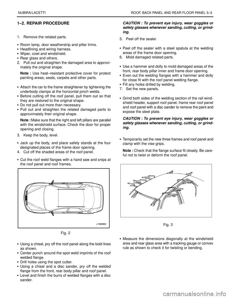
S Temporarily set the new three frames and roof panel and
clamp with the vise grips.
Note : Check that the flange surface fit closely. Be care-
ful not to twist or deform the roof panel.
Fig. 3
S Measure the dimensions diagonally at the windshield
area and rear glass area with a tracking gauge or convex
rule as shown to check it for twisting or bending.
Page 2568 of 2643
NUBIRA/LACETTI FRAME DOOR OPENING, DOOR AND SIDE PANEL OUTER 6–3
1–2. REPAIR PROCEDURE
1. Remove the related parts.
S Doors.
S Weather strips, pillar trims and related parts.
S Carpet.
S Seat belt assembly
S Door switch and wiring harness.
S Fuel pipe and brake oil pipe.
S Other related parts.
Note : Pull out and straighten the damaged area to
approximately the original shape.
2. Remove the related parts.
S Damage may extend to the inner roof frame, the inner
frame door opening and the floor. Determine the extent
of the damage first, so the frame can be pulled out prop-
erly.
Note : Use heat–resistant protective cover for protect
painting areas, seats, carpets and other parts.
S Pull out and straighten the damaged areas.
S Do not pull out more than necessary.
3. Cut and pry off the frame door opening.
S Check the damage on the frame door opening, then cut
the new frame door opening so it will overlap by
30mm(1.18in.) in the pillar, front and rear.
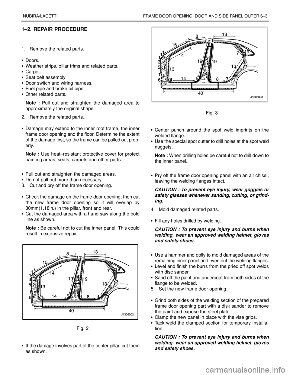
S Cut the damaged area with a hand saw along the bold
line as shown.
Note : Be careful not to cut the inner panel. This could
result in extensive repair.
Fig. 2
S If the damage involves part of the center pillar, cut them
as shown.
Fig. 3
S Center punch around the spot weld imprints on the
welded flange.
S Use the special spot cutter to drill holes at the spot weld
nuggets.
Note : When drilling holes be careful not to drill down to
the inner panel..
S Pry off the frame door opening panel with an air chisel,
leaving the welding flanges intact.
CAUTION : To prevent eye injury, wear goggles or
safety glasses whenever sanding, cutting, or grind-
ing.
4. Mold damaged related parts.
S Fill any holes drilled by welding.
CAUTION : To prevent eye injury and burns when
welding, wear an approved welding helmet, gloves
and safety shoes.
S Use a hammer and dolly to mold damaged areas of the
remaining inner panel and even out the welding flanges.
S Level and finish the burrs from the pried off spot welds
with disc sander.
S Sand off the paint and undercoat from both sides of the
flange to be welded.
5. Set the new frame door opening.
S Grind both sides of the welding section of the prepared
frame door opening part with a disk sander to remove
the paint and expose the steel plate.
S Clamp the new panel in place with the vise grips.
S Tack weld the clamped section for temporary installa-
tion.
CAUTION : To prevent eye injury and burns when
welding, wear an approved welding helmet, gloves
and safety shoes.
Page 2617 of 2643
9–14 SEALING, CAULKING AND DEADNER NUBIRA/LACETTI
2. DEADNER
2–1. GENERAL DESCRIPTION
.
Deadner is properly designed and applied for reduce the
vibration and noise. Also, it plays in maintaining the
structural rigidity of the panel.
.
2–2. REPAIR PROCEDURE
.
1. Remove the related parts.
S Seats, carpet.
S Trims, others.
.
2. Removal of the damaged deadner.
S Peel off the damaged deadner with a steel spatula, care-
fully.
.
3. Clean and dry.
S Before applying the deadner, thoroughly clean and dry
the areas to be applied.
.
4. Prelocation the new deadner on the panels to be ap-
plied.
.
Note : Avoid the parts mounting holes and service holes.
.
5. Adhension of deadner.
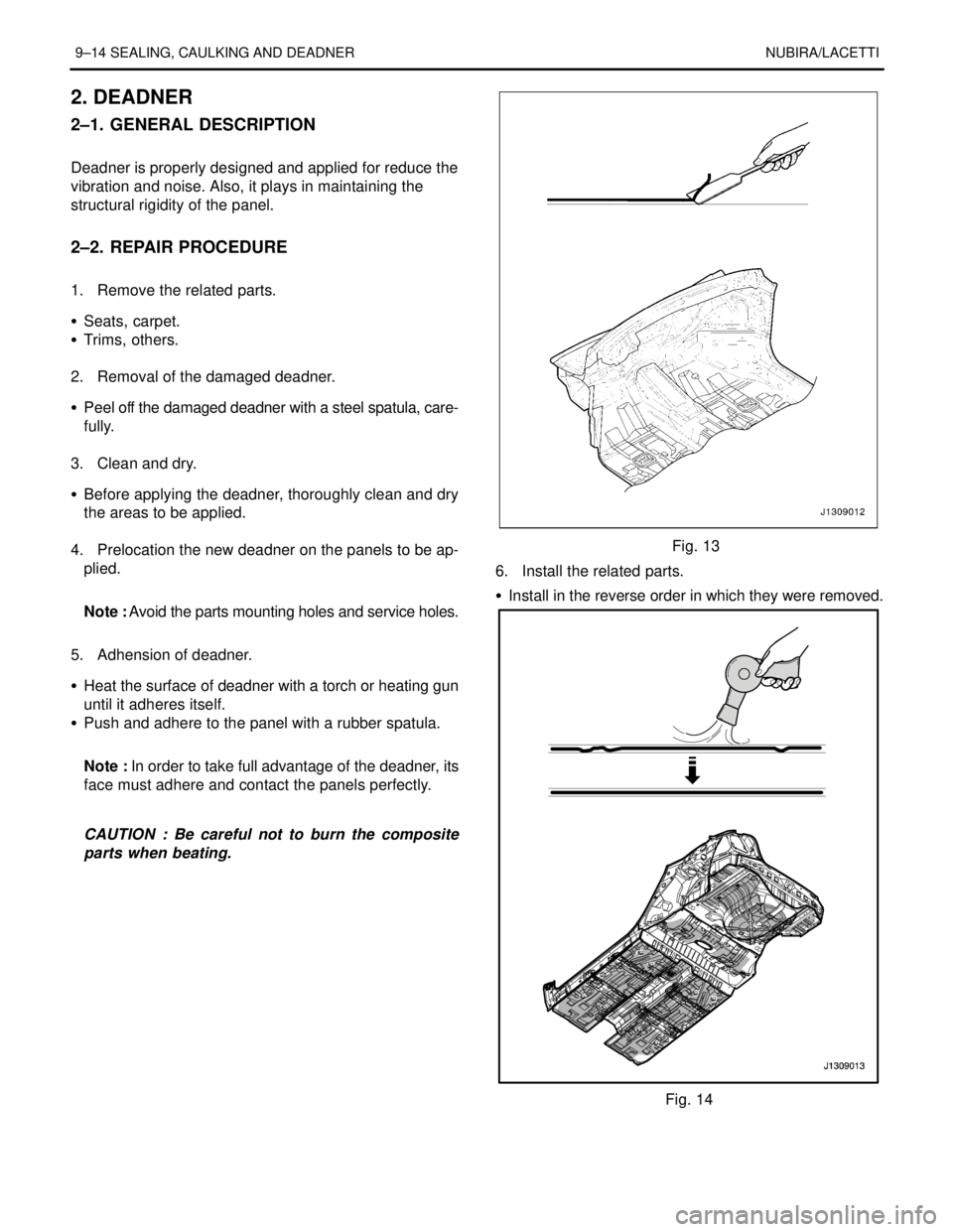
S Heat the surface of deadner with a torch or heating gun
until it adheres itself.
S Push and adhere to the panel with a rubber spatula.
.
Note : In order to take full advantage of the deadner, its
face must adhere and contact the panels perfectly.
.
CAUTION : Be careful not to burn the composite
parts when beating.
Fig. 13
6. Install the related parts.
S Install in the reverse order in which they were removed.
Fig. 14