Page 1850 of 2643
5B – 26IFIVE–SPEED MANUAL TRANSAXLE
DAEWOO V–121 BL4
UNIT REPAIR
MAJOR COMPONENT DISASSEMBLY
Tools Required
J–6125–B Slide Hammer
J–22888–20–A BearingPuller with J–22888–35 Puller
Legs
KM–553–A Fifth Gear Puller
J–36633 Snap Ring Retainer
KM–113–2 Base
J–42469 Shift Rod Remover
KM–552 Fixture
Disassembly Procedure
1. Remove the transaxle from the vehicle. Refer to
”Transaxle Assembly” in this section.
2. Remove the filler plug at the cover.
3. Remove the bolts from the gearshift lever cover.
4. Remove the gearshift lever cover.
Page 1872 of 2643
5B – 48IFIVE–SPEED MANUAL TRANSAXLE
DAEWOO V–121 BL4
HOUSING CASE
Disassembly Procedure
1. Remove the transaxle from the vehicle. Refer to
”Transaxle Assembly” in this section.
2. Remove the shift lever cover bolts and the shift le-
ver cover. Do not disassemble the shift lever cover.
3. Remove the transaxle cover bolts and the transaxle
cover.
4. Remove the bearing plate bolts and the bearing
plate, with the shafts attached. Do not disassemble
the shafts.
5. Remove the differential from the transaxle housing.
Do not disassemble the differential. Refer to ”Differ-
ential” in this section.
6. Remove the backup lamp switch from the transaxle
housing.
Page 1873 of 2643
FIVE–SPEED MANUAL TRANSAXLE 5B – 49
DAEWOO V–121 BL4
7. Remove the clutch–release bearing and the clutch–
release bearing guide. Refer to Section 5C, Clutch.
8. Remove the speedometer–driven gear bolt and the
speedometer–driven gear from the transaxle hous-
ing.
Assembly Procedure
1. Install the speedometer–driven gear bolt and the
speedometer–driven gear into the transaxle hous-
ing.
Tighten
Tighten the speedometer–driven gear bolt to 5 NSm
(44 lb–in)
2. Install the clutch–release bearing guide and the
clutch–release bearing. Refer to Section 5C,
Clutch.
3. Install the backup lamp switch into the transaxle
housing.
Tighten
Tighten the backup lamp switch to 20 NSm (15 lb–ft).
4. Install the differential into the transaxle housing.
Refer to ”Differential” in this section.
5. Install the bearing plate, with the shafts attached.
6. Install the bearing plate bolts.
Tighten
Tighten the bearing plate bolts to 22 NSm (16 lb–ft).
Page 1874 of 2643
5B – 50IFIVE–SPEED MANUAL TRANSAXLE
DAEWOO V–121 BL4
7. Install the transaxle cover and the transaxle cover
bolts.
Tighten
Tighten the transaxle cover bolts to 18 NSm (13 lb–ft).
8. Install the gearshift lever cover and the gearshift
lever cover bolts.
Tighten
Tighten the gearshift lever cover bolts to 22 NSm (16
lb–ft).
9. Install the transaxle into the vehicle. Refer to
”Transaxle Assembly” in this section.
DIFFERENTIAL
Tools Required
KM–520 Remover/Installer
KM–525 Installer
J–22888–20–A Bearing Puller with J–22888–35 Puller
Legs
KM–522 Installer
Disassembly Procedure
1. Remove the differential cover bolts, the differential
cover, and the differential cover gasket.
2. Remove the bearing–adjusting ring retainer plate
bolt and the bearing–adjusting ring retainer plate.
Page 1886 of 2643
5B – 62IFIVE–SPEED MANUAL TRANSAXLE
DAEWOO V–121 BL4
31. Bolt the gearshift lever cover to the fixture KM–552.
32. Position the fixture into the base KM–113–2.
33. Install the gearshift rod, the shift finger lever, and
the gearshift lever pin.
34. Install the snap ring, the bushing, the spring, and
the intermediate lever.
35. Remove the gearshift lever cover from the base
KM–113–2 and the fixture KM–552.
36. Shift the transaxle into NEUTRAL.
37. Install the gearshift lever cover and the gearshift
lever cover bolts.
Tighten
Tighten the gearshift lever cover bolts to 22 NSm (16
lb–ft).
38. Install the transaxle cover and the transaxle cover
bolts.
Tighten
Tighten the transaxle cover bolts to 18 NSm (13 lb–ft).
39. Install the transaxle into the vehicle. Refer to
”Transaxle Assembly” in this section.
Page 1888 of 2643

SECTION : 5C
CLUTCH
CAUTION : Disconnect the negative battery cable before removing or installing any electrical unit or when a tool
or equipment could easily come in contact with exposed electrical terminals. Disconnecting this cable will help
prevent personal injury and damage to the vehicle. The ignition must also be in LOCK unless otherwise noted.
TABLE OF CONTENTS
SPECIFICATIONS5C–1 . . . . . . . . . . . . . . . . . . . . . . . . . .
Fastener Tightening Specifications 5C–1. . . . . . . . . . .
SPECIAL TOOLS5C–2 . . . . . . . . . . . . . . . . . . . . . . . . . . .
Special Tools Table 5C–2. . . . . . . . . . . . . . . . . . . . . . . .
DIAGNOSIS5C–2 . . . . . . . . . . . . . . . . . . . . . . . . . . . . . . . .
Clutch Operation 5C–2. . . . . . . . . . . . . . . . . . . . . . . . . .
COMPONENT LOCATOR5C–4 . . . . . . . . . . . . . . . . . . . .
Clutch Components 5C–4. . . . . . . . . . . . . . . . . . . . . . . .
MAINTENANCE AND REPAIR5C–6 . . . . . . . . . . . . . . .
ON–VEHICLE SERVICE 5C–6. . . . . . . . . . . . . . . . . . . . .
Clutch Pedal 5C–6. . . . . . . . . . . . . . . . . . . . . . . . . . . . . . Clutch Pedal Adjustment 5C–7. . . . . . . . . . . . . . . . . . . .
Clutch Release Point Adjustment 5C–8. . . . . . . . . . . .
Air Bleeding 5C–8. . . . . . . . . . . . . . . . . . . . . . . . . . . . . . .
Pressure Plate and Clutch Disc 5C–8. . . . . . . . . . . . . .
Clutch Master Cylinder Assembly 5C–10. . . . . . . . . . .
Concentric Slave Cylinder 5C–12. . . . . . . . . . . . . . . . . .
GENERAL DESCRIPTION AND SYSTEM
OPERATION5C–14 . . . . . . . . . . . . . . . . . . . . . . . . . . . . .
Driving Members 5C–14. . . . . . . . . . . . . . . . . . . . . . . . .
Driven Members 5C–14. . . . . . . . . . . . . . . . . . . . . . . . . .
Operating Members 5C–14. . . . . . . . . . . . . . . . . . . . . . .
SPECIFICATIONS
FASTENER TIGHTENING SPECIFICATIONS
ApplicationNSmLb–FtLb–In
Clutch Master Cylinder nuts2216–
Concentric Slave Cylinder Retaining Bolts7–62
Concentric Slave Cylinder–to–Clutch Oil Pipe Screw1511–
Pressure Plate–to–Flywheel Bolts1511–
Page 1894 of 2643

CLUTCH 5C – 7
DAEWOO V–121 BL4
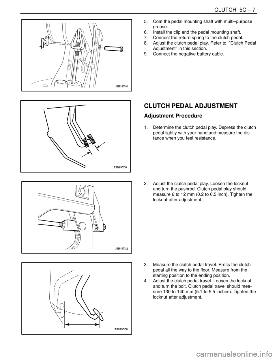
5. Coat the pedal mounting shaft with multi–purpose
grease.
6. Install the clip and the pedal mounting shaft.
7. Connect the return spring to the clutch pedal.
8. Adjust the clutch pedal play. Refer to ”Clutch Pedal
Adjustment” in this section.
9. Connect the negative battery cable.
CLUTCH PEDAL ADJUSTMENT
Adjustment Procedure
1. Determine the clutch pedal play. Depress the clutch
pedal lightly with your hand and measure the dis-
tance when you feel resistance.
2. Adjust the clutch pedal play. Loosen the locknut
and turn the pushrod. Clutch pedal play should
measure 6 to 12 mm (0.2 to 0.5 inch). Tighten the
locknut after adjustment.
3. Measure the clutch pedal travel. Press the clutch
pedal all the way to the floor. Measure from the
starting position to the ending position.
4. Adjust the clutch pedal travel. Loosen the locknut
and turn the bolt. Clutch pedal travel should mea-
sure 130 to 140 mm (5.1 to 5.5 inches). Tighten the
locknut after adjustment.
Page 1895 of 2643

5C – 8ICLUTCH
DAEWOO V–121 BL4
CLUTCH RELEASE POINT
ADJUSTMENT
Adjustment Procedure
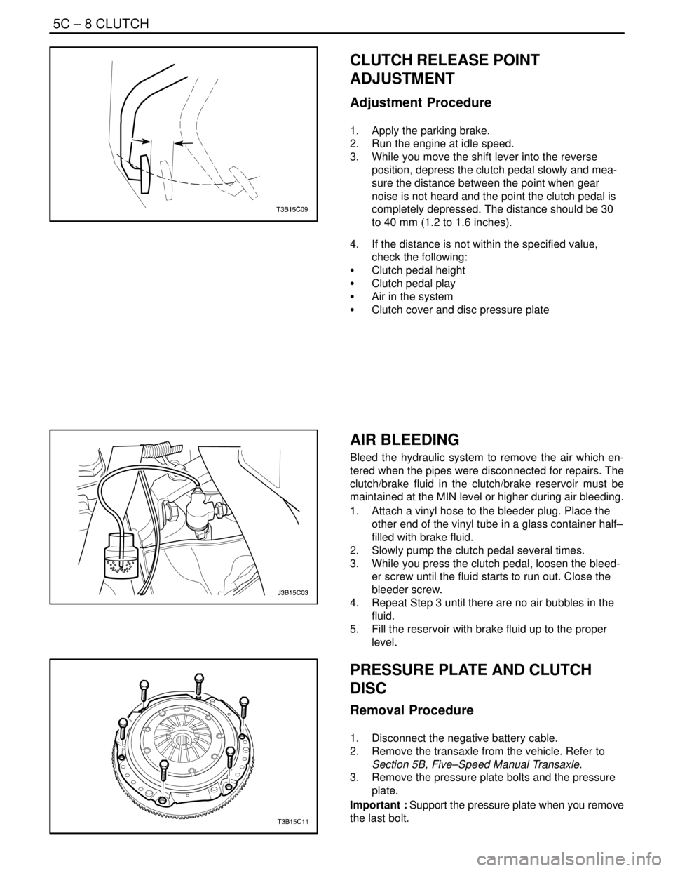
1. Apply the parking brake.
2. Run the engine at idle speed.
3. While you move the shift lever into the reverse
position, depress the clutch pedal slowly and mea-
sure the distance between the point when gear
noise is not heard and the point the clutch pedal is
completely depressed. The distance should be 30
to 40 mm (1.2 to 1.6 inches).
4. If the distance is not within the specified value,
check the following:
S Clutch pedal height
S Clutch pedal play
S Air in the system
S Clutch cover and disc pressure plate
AIR BLEEDING
Bleed the hydraulic system to remove the air which en-
tered when the pipes were disconnected for repairs. The
clutch/brake fluid in the clutch/brake reservoir must be
maintained at the MIN level or higher during air bleeding.
1. Attach a vinyl hose to the bleeder plug. Place the
other end of the vinyl tube in a glass container half–
filled with brake fluid.
2. Slowly pump the clutch pedal several times.
3. While you press the clutch pedal, loosen the bleed-
er screw until the fluid starts to run out. Close the
bleeder screw.
4. Repeat Step 3 until there are no air bubbles in the
fluid.
5. Fill the reservoir with brake fluid up to the proper
level.
PRESSURE PLATE AND CLUTCH
DISC
Removal Procedure
1. Disconnect the negative battery cable.
2. Remove the transaxle from the vehicle. Refer to
Section 5B, Five–Speed Manual Transaxle.
3. Remove the pressure plate bolts and the pressure
plate.
Important : Support the pressure plate when you remove
the last bolt.