2004 DAEWOO LACETTI Section 6
[x] Cancel search: Section 6Page 1965 of 2643

STEERING WHEEL AND COLUMN 6E – 11
DAEWOO V–121 BL4
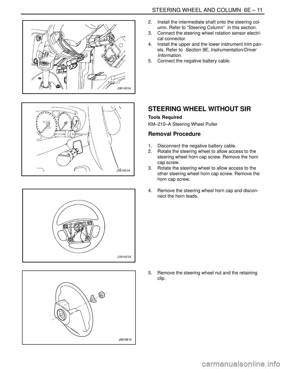
2. Install the intermediate shaft onto the steering col-
umn. Refer to ”Steering Column” in this section.
3. Connect the steering wheel rotation sensor electri-
cal connector.
4. Install the upper and the lower instrument trim pan-
els. Refer to Section 9E, Instrumentation/Driver
Information.
5. Connect the negative battery cable.
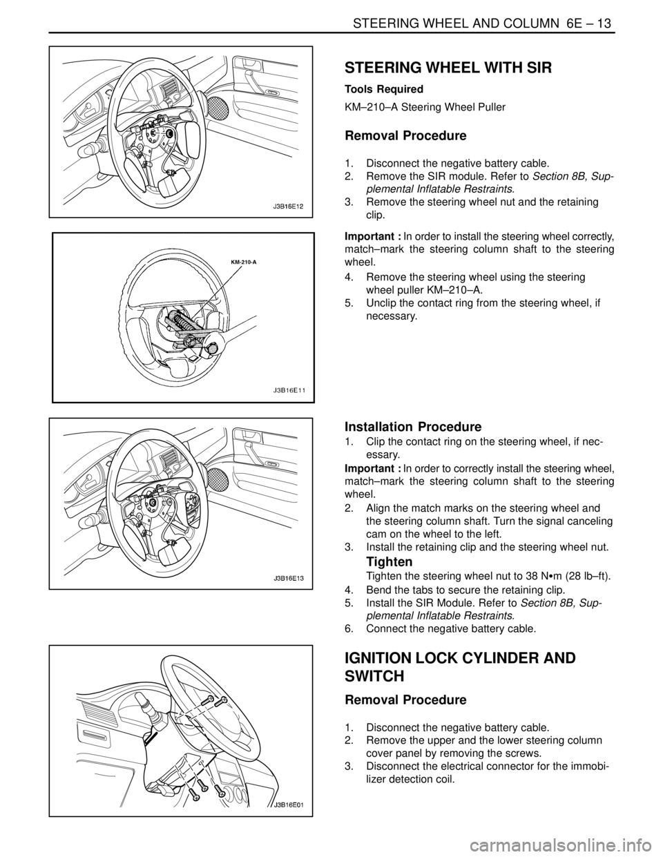
STEERING WHEEL WITHOUT SIR
Tools Required
KM–210–A Steering Wheel Puller
Removal Procedure
1. Disconnect the negative battery cable.
2. Rotate the steering wheel to allow access to the
steering wheel horn cap screw. Remove the horn
cap screw.
3. Rotate the steering wheel to allow access to the
other steering wheel horn cap screw. Remove the
horn cap screw.
4. Remove the steering wheel horn cap and discon-
nect the horn leads.
5. Remove the steering wheel nut and the retaining
clip.
Page 1967 of 2643

STEERING WHEEL AND COLUMN 6E – 13
DAEWOO V–121 BL4
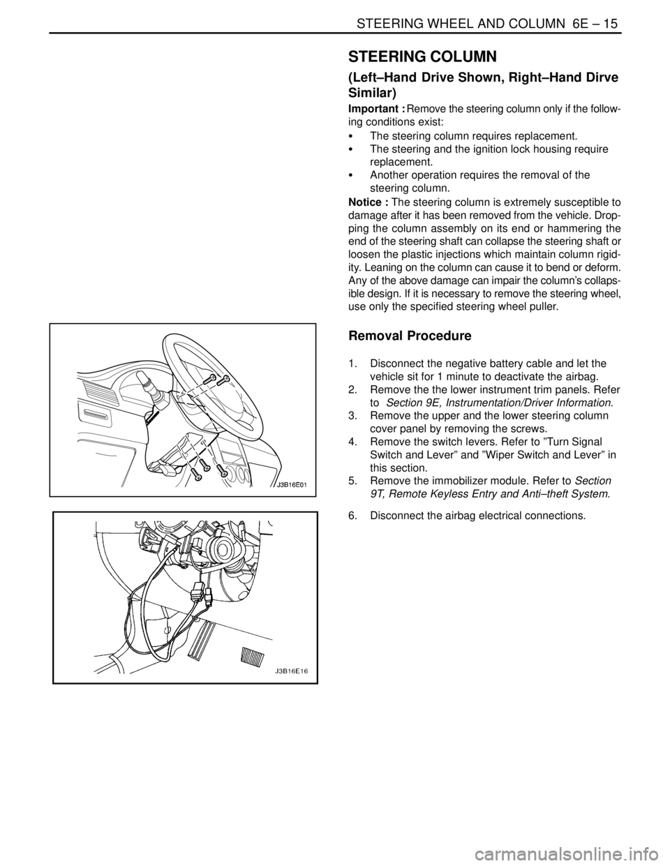
STEERING WHEEL WITH SIR
Tools Required
KM–210–A Steering Wheel Puller
Removal Procedure
1. Disconnect the negative battery cable.
2. Remove the SIR module. Refer to Section 8B, Sup-
plemental Inflatable Restraints.
3. Remove the steering wheel nut and the retaining
clip.
Important : In order to install the steering wheel correctly,
match–mark the steering column shaft to the steering
wheel.
4. Remove the steering wheel using the steering
wheel puller KM–210–A.
5. Unclip the contact ring from the steering wheel, if
necessary.
Installation Procedure
1. Clip the contact ring on the steering wheel, if nec-
essary.
Important : In order to correctly install the steering wheel,
match–mark the steering column shaft to the steering
wheel.
2. Align the match marks on the steering wheel and
the steering column shaft. Turn the signal canceling
cam on the wheel to the left.
3. Install the retaining clip and the steering wheel nut.
Tighten
Tighten the steering wheel nut to 38 NSm (28 lb–ft).
4. Bend the tabs to secure the retaining clip.
5. Install the SIR Module. Refer to Section 8B, Sup-
plemental Inflatable Restraints.
6. Connect the negative battery cable.
IGNITION LOCK CYLINDER AND
SWITCH
Removal Procedure
1. Disconnect the negative battery cable.
2. Remove the upper and the lower steering column
cover panel by removing the screws.
3. Disconnect the electrical connector for the immobi-
lizer detection coil.
Page 1969 of 2643

STEERING WHEEL AND COLUMN 6E – 15
DAEWOO V–121 BL4
STEERING COLUMN
(Left–Hand Drive Shown, Right–Hand Dirve
Similar)
Important : Remove the steering column only if the follow-
ing conditions exist:
S The steering column requires replacement.
S The steering and the ignition lock housing require
replacement.
S Another operation requires the removal of the
steering column.
Notice : The steering column is extremely susceptible to
damage after it has been removed from the vehicle. Drop-
ping the column assembly on its end or hammering the
end of the steering shaft can collapse the steering shaft or
loosen the plastic injections which maintain column rigid-
ity. Leaning on the column can cause it to bend or deform.
Any of the above damage can impair the column’s collaps-
ible design. If it is necessary to remove the steering wheel,
use only the specified steering wheel puller.
Removal Procedure
1. Disconnect the negative battery cable and let the
vehicle sit for 1 minute to deactivate the airbag.
2. Remove the the lower instrument trim panels. Refer
to Section 9E, Instrumentation/Driver Information.
3. Remove the upper and the lower steering column
cover panel by removing the screws.
4. Remove the switch levers. Refer to ”Turn Signal
Switch and Lever” and ”Wiper Switch and Lever” in
this section.
5. Remove the immobilizer module. Refer to Section
9T, Remote Keyless Entry and Anti–theft System.
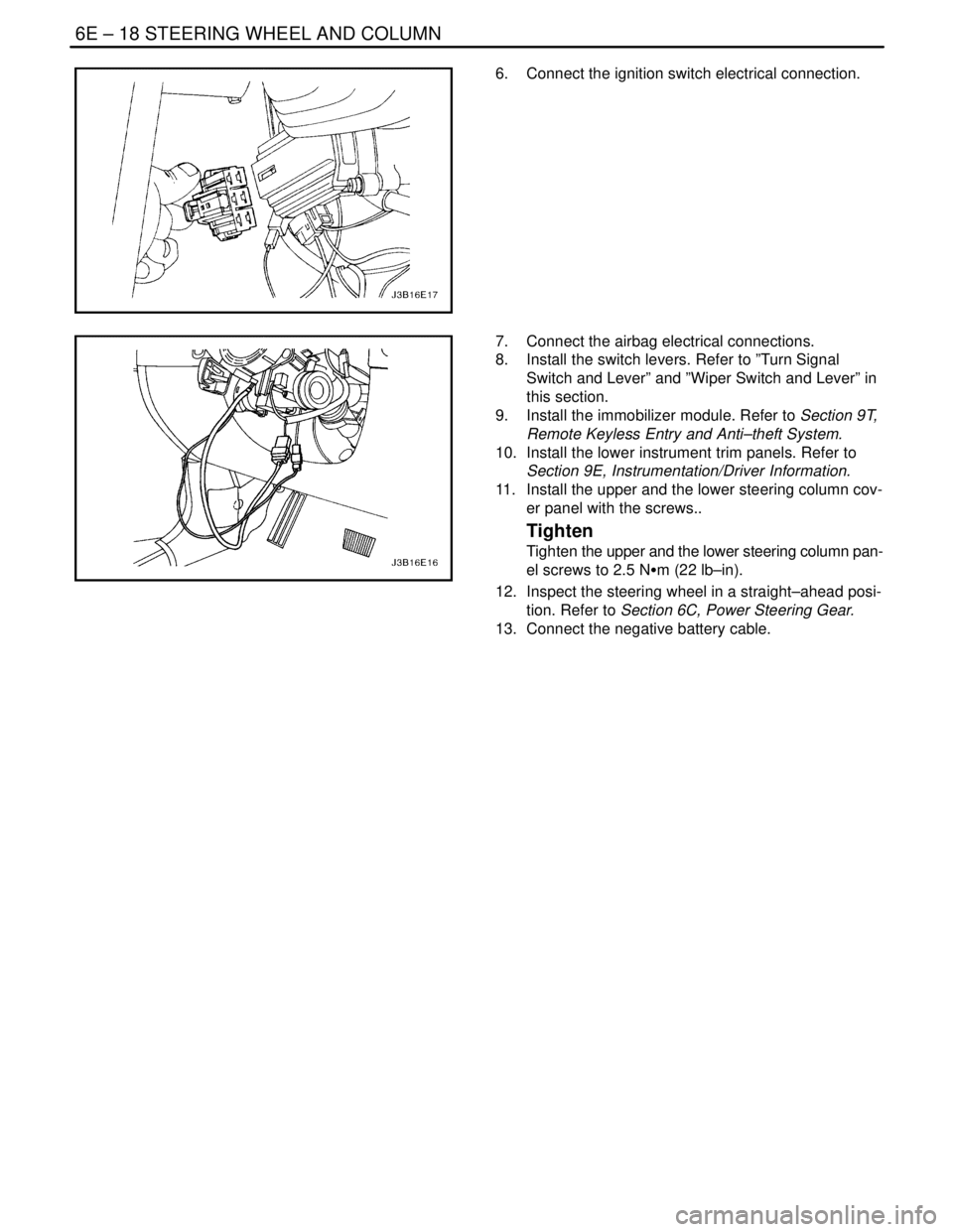
6. Disconnect the airbag electrical connections.
Page 1972 of 2643

6E – 18ISTEERING WHEEL AND COLUMN
DAEWOO V–121 BL4
6. Connect the ignition switch electrical connection.
7. Connect the airbag electrical connections.
8. Install the switch levers. Refer to ”Turn Signal
Switch and Lever” and ”Wiper Switch and Lever” in
this section.
9. Install the immobilizer module. Refer to Section 9T,
Remote Keyless Entry and Anti–theft System.
10. Install the lower instrument trim panels. Refer to
Section 9E, Instrumentation/Driver Information.
11. Install the upper and the lower steering column cov-
er panel with the screws..
Tighten
Tighten the upper and the lower steering column pan-
el screws to 2.5 NSm (22 lb–in).
12. Inspect the steering wheel in a straight–ahead posi-
tion. Refer to Section 6C, Power Steering Gear.
13. Connect the negative battery cable.
Page 1974 of 2643

6E – 20ISTEERING WHEEL AND COLUMN
DAEWOO V–121 BL4
GENERAL DESCRIPTION
AND SYSTEM OPERATION
STEERING WHEEL AND COLUMN
CAUTION : To ensure the energy–absorbing action of
the steering column, it is important to use only the
specified screws, bolts, and nuts, tightened to the
specified torque.
In addition to the steering function, the steering column
provides safety and security.
The energy–absorbing column is designed to compress in
a front–end collision to lessen the chance of driver injury.
The ignition switch and the lock are mounted on the col-
umn, allowing the ignition and steering operations to be
locked to inhibit theft of the car.
The column levers trigger the turn signals, the headlight
beams, and the windshield washer and wipers.The tilt steering column uses telescopic function to allow
the steering wheel to tilt up and down in and out. This en-
ables the driver to adjust the steering wheel to a comfort-
able position.
Notice : Apply a thin coat of lithium grease to all friction
points when reassembling.
The column may be disassembled and reassembled easi-
ly.IGNITION KEY REMINDER
The ignition key reminder alerts the driver that the key is
still in the ignition when the driver attempts to exit the ve-
hicle.
An internal switch in the ignition lock cylinder supplies bat-
tery voltage to the reminder chime module when all of the
following conditions are true:
S The key is in the ignition switch.
S The ignition is OFF.
S The driver’s door is open.
For information on removal and installation of the reminder
chime module, refer to Section 9E, Instrumentation/Driver
Information.
Page 1975 of 2643

SECTION : 7A
HEATING AND VENTILATION SYSTEM
CAUTION : Disconnect the negative battery cable before removing or installing any electrical unit or when a tool
or equipment could easily come in contact with exposed electrical terminals. Disconnecting this cable will help
prevent personal injury and damage to the vehicle. The ignition must also be in LOCK unless otherwise noted.
TABLE OF CONTENTS
SPECIFICATIONS7A–1 . . . . . . . . . . . . . . . . . . . . . . . . . .
Heater Temperature Specifications 7A–1. . . . . . . . . . .
Fastener Tightening Specifications 7A–1. . . . . . . . . . .
SCHEMATIC AND ROUTING DIAGRAMS7A–3 . . . . .
Non–A/C Diagrams 7A–3. . . . . . . . . . . . . . . . . . . . . . . .
Airflow – Typical 7A–4. . . . . . . . . . . . . . . . . . . . . . . . . . .
Airflow with Rear Heating Duct 7A–5. . . . . . . . . . . . . .
DIAGNOSIS7A–6 . . . . . . . . . . . . . . . . . . . . . . . . . . . . . . . .
HEATER SYSTEM 7A–6. . . . . . . . . . . . . . . . . . . . . . . . . .
Insufficient Heating or Defrosting 7A–6. . . . . . . . . . . . .
Blower Electrical 7A–9. . . . . . . . . . . . . . . . . . . . . . . . . . .
Improper Air delivery or No Mode Shift 7A–11. . . . . .
Too Much Heat 7A–13. . . . . . . . . . . . . . . . . . . . . . . . . . .
Controls 7A–15. . . . . . . . . . . . . . . . . . . . . . . . . . . . . . . . .
Blower Noise 7A–16. . . . . . . . . . . . . . . . . . . . . . . . . . . . . MAINTENANCE AND REPAIR7A–18 . . . . . . . . . . . . . .
ON–VEHICLE SERVICE 7A–18. . . . . . . . . . . . . . . . . . . .
Temperature Cable Adjustment 7A–18. . . . . . . . . . . . .
Temperature Control Cable 7A–18. . . . . . . . . . . . . . . . .
Control Assembly 7A–20. . . . . . . . . . . . . . . . . . . . . . . . .
Control Assembly Knob Lighting 7A–21. . . . . . . . . . . .
Heater/Air Distributor Case Assembly 7A–21. . . . . . .
Blower Motor 7A–23. . . . . . . . . . . . . . . . . . . . . . . . . . . . .
High–Blower Relay 7A–24. . . . . . . . . . . . . . . . . . . . . . . .
Blower Resistor 7A–25. . . . . . . . . . . . . . . . . . . . . . . . . .
Heater Hoses 7A–25. . . . . . . . . . . . . . . . . . . . . . . . . . . .
Heater Core 7A–26. . . . . . . . . . . . . . . . . . . . . . . . . . . . . .
GENERAL DESCRIPTION AND SYSTEM
OPERATION7A–28 . . . . . . . . . . . . . . . . . . . . . . . . . . . . .
Heating and Ventilation Systems 7A–28. . . . . . . . . . . .
SPECIFICATIONS
HEATER TEMPERATURE SPECIFICATIONS
Ambient Air TemperatureHeater Outlet Air Temperature
–18°C (0°F)54°C (129°F)
– 4°C (25°F)59°C (138°F)
10°C (50°F)64°C (147°F)
24°C (75°F)68°C (154°F)
FASTENER TIGHTENING SPECIFICATIONS
ApplicationNSmLb–FtLb–In
Blower Motor–to–A/C Assembly Screws1.2–11
Blower Motor Resistor Screws1.2–11
Blower Motor Retaining Screws1.2–11
Controller Retaining Screws2–18
Heater/Air Distributor Case Assembly Screw4–35
Page 1980 of 2643

7A – 6IHEATING AND VENTILATION SYSTEM
DAEWOO V–121 BL4
DIAGNOSIS
HEATER SYSTEM
INSUFFICIENT HEATING OR DEFROSTING
CAUTION : The cooling system is pressurized when hot. Injury can result from removing the surge tank cap be-
fore the engine is sufficiently cool.
Step
ActionValue(s)YesNo
1Verify the customer’s complaint.
Are the customer’s concerns verified?–Go to Step 2System OK
2Check the coolant level.
Is the coolant level correct?–Go to Step 4Go to Step 3
3Add coolant as needed.
Is the repair complete?–System OKGo to Step 4
4Check the timing belt for tension or damage.
Are the drive belts OK?–Go to Step 6Go to Step 5
5Correct any problem with the timing belt.
Is the repair complete?–System OKGo to Step 6
6Check the coolant hoses for leaks or kinks.
Are the coolant hoses OK?–Go to Step 8Go to Step 7
7Repair any problem with the coolant hoses.
Is the repair complete?–System OKGo to Step 8
8Check the surge tank cap. Refer to Section 2D, En-
gine Cooling.
Is the surge tank cap OK?–Go to Step 10Go to Step 9
9Repair or replace the surge tank cap as needed.
Is the repair complete?–System OKGo to Step 10
101. Turn the A/C switch OFF on vehicles equipped
with air conditioning (A/C).
2. Set the blower motor switch on maximum
speed.
3. Set the heater control to full hot.
4. Turn the ignition ON.
5. Check for airflow from the vent outlet.
Is there heavy airflow from the heater outlet?–Go to Step 11Go to Step 26
11Check for a change in the airflow at various blower
speeds.
Does the blower speed increase as the switch is
turned from 1 to 4.–Go to Step 12Go to ”Blower
Electrical
(Manual and
Non–A/C)”
121. Turn the A/C switch OFF.
2. Set the temperature lever to full hot.
3. Set the blower motor switch on maximum
speed.
4. With the engine sufficiently cool, remove the
surge tank cap.
5. Start the vehicle and idle the engine.
6. Watch for the flow of the coolant.
Is the coolant flow visible?–Go to Step 14Go to Step 13
Page 1982 of 2643

7A – 8IHEATING AND VENTILATION SYSTEM
DAEWOO V–121 BL4
StepNo Yes Value(s) Action
20Replace the thermostat. Refer to Section 2D, En-
gine Cooling.
Is the repair complete?–System OK–
21Reinstall the thermostat.
Is the repair complete?–System OK–
22Inspect the heater hoses for proper installation.
Are the heater hoses reversed?–Go to Step 23Go to Step 24
23Reinstall the heater hoses properly.
Is the repair complete?–System OK–
241. Back flush the heater core.
2. Drain the cooling system.
3. Replace the coolant.
4. Warm the engine to an average operating tem-
perature.
5. Feel the heater inlet hose and the heater outlet
hose.
Is the heater inlet hose hot and the heater outlet
hose warm?–System OKGo to Step 25
25Replace the heater core.
Is the repair complete?–System OK–
26Recheck the system using the ”Control Settings/
Correct Results” tests. Refer to ”Improper Air Deliv-
ery or No Mode Shift” in this section.
Is the repair complete?–System OKGo to Step 27
27Check for airflow from the defroster or the vent out-
lets.
Is there high airflow from the defroster or vent out-
lets?–Go to Step 28Go to Step 29
281. Check the heater door at the floor and the vent
door to get the proper airflow and to verify
proper operation.
2. Repair as required.
Is the repair complete?–System OK–
29Switch the mode knob to defrost.
Is the defroster airflow OK?–Go to Step 30Go to Step 31
301. Remove the heater outlet and check for ob-
structions.
2. Remove any obstructions in the heater outlet.
Is the repair complete?–System OK–
31Check for airflow change at various blower speeds.
Does the blower speed increase as the control is
turned from 1 to 4?–Go to Step 32Go to ”Blower
Electrical
(Manual and
Non–A/C)”
32Check for obstructions in the system at the blower
inlet and at the air filter, if the vehicle is equipped with
one.
Are there any obstructions?–Go to Step 33Go to Step 34
33Remove the obstructions in the system at the blower
inlet or replace a clogged filter.
Is the repair complete?–System OK–