Page 1942 of 2643
POWER STEERING GEAR 6C – 25
DAEWOO V–121 BL4
5. Install the cylinder end dust boot retaining clamps
with the installer KM–J–22610.
6. Install the tie rod end boot retaining clamps.
7. Reposition the adjusting nut to the marks on the
inner tie rod and install the outer tie rod by twisting
it onto the inner tie rod.
8. Perform a front toe adjustment. Refer to Section
2B, Wheel Alignment.
9. Tighten the adjusting nut.
Tighten
Tighten the outer tie rod adjusting nut to 64 NSm (47
lb–ft).
10. Install the rack bearing assembly into the rack and
pinion steering assembly. Refer to ”Rack Bearing”
in this section.
11. Install the valve and pinion assembly into the rack
and pinion steering assembly. Refer to ”Valve and
Pinion” in this section.
12. Install the rack and pinion steering assembly into
the vehicle. Refer to ”Rack and Pinion Assembly”
in this section.
Page 1943 of 2643
6C – 26IPOWER STEERING GEAR
DAEWOO V–121 BL4
STUB SHAFT SEALS AND UPPER
AND LOWER BEARING
Disassembly Procedure
1. Remove the rack and pinion steering assembly
from the vehicle. Refer to ”Rack and Pinion Assem-
bly” in this section.
2. Remove the dust cover from the lower end of the
housing.
Notice : If the stub shaft is not held, damage to the pinion
teeth will occur.
3. While holding the stub shaft with a wrench, remove
the locknut from the pinion.
4. With the gear centered, mark the location of the
stub shaft notch on the housing to aid in properly
installing the valve and pinion assembly.
5. Remove the stub shaft retaining ring and, using an
arbor press, press on the threaded end of the pin-
ion until it is possible to remove the pinion and
valve assembly from the housing.
Page 1945 of 2643
6C – 28IPOWER STEERING GEAR
DAEWOO V–121 BL4
2. Install the lower valve assembly bearing and the
bushing.
3. Center the rack in the housing.
4. Install the the valve assembly, the stub shaft bear-
ing annulus assembly and a new stub shaft dust
seal into the housing.
Important : When the valve and pinion assembly is fully
seated in the housing, be sure that the notch in the stub
shaft and the mark on the housing line up.
Notice : If the stub shaft is not held, damage to the pinion
teeth will occur.
5. While holding the stub shaft, install the locknut onto
the pinion shaft.
Tighten
Tighten the pinion locknut to 30 NSm (22 lb–ft).
6. Replace the dust cover onto the housing.
7. Install the rack and pinion steering assembly. Refer
to ”Rack and Pinion Assembly” in this section.
Page 1946 of 2643

POWER STEERING GEAR 6C – 29
DAEWOO V–121 BL4
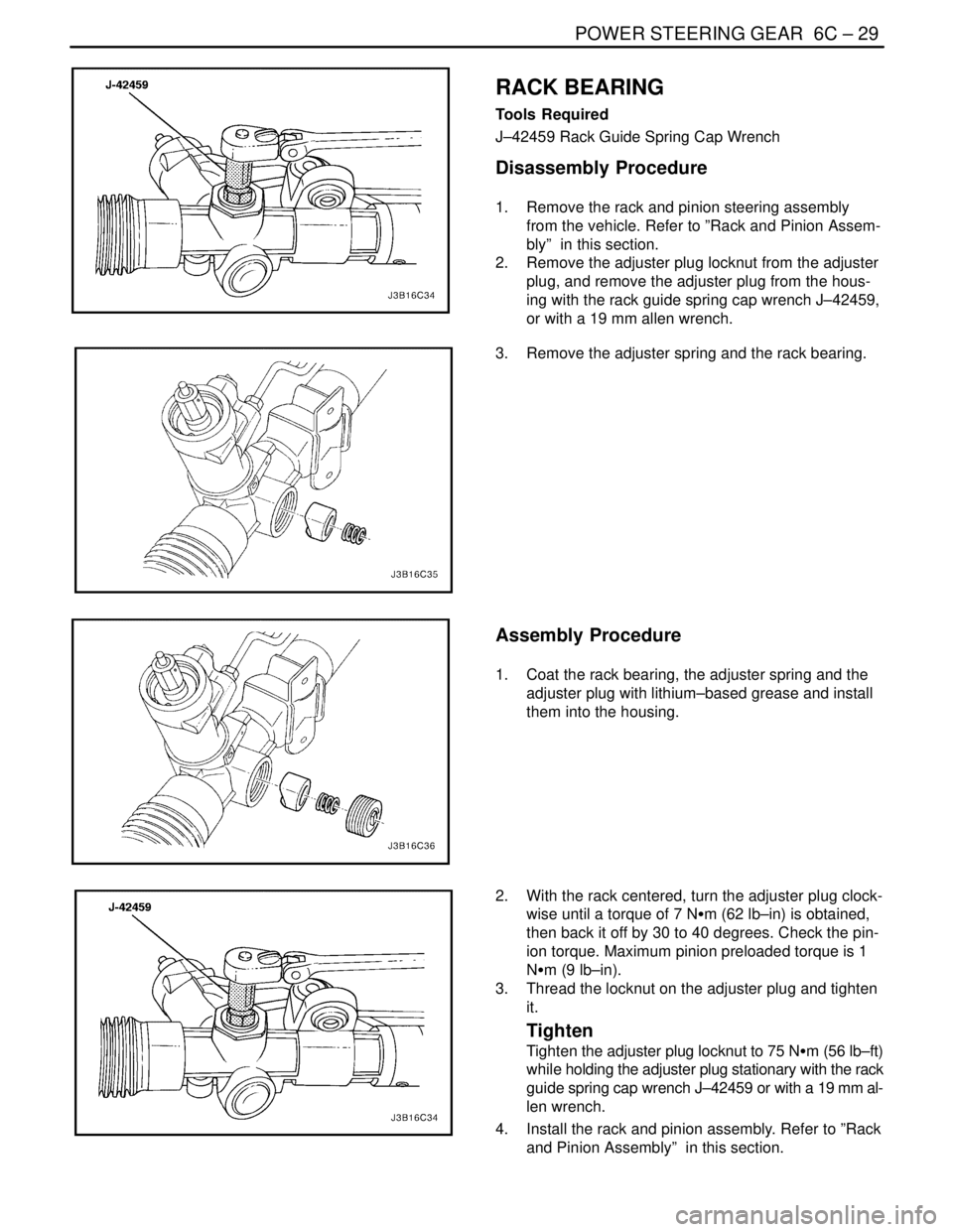
RACK BEARING
Tools Required
J–42459 Rack Guide Spring Cap Wrench
Disassembly Procedure
1. Remove the rack and pinion steering assembly
from the vehicle. Refer to ”Rack and Pinion Assem-
bly” in this section.
2. Remove the adjuster plug locknut from the adjuster
plug, and remove the adjuster plug from the hous-
ing with the rack guide spring cap wrench J–42459,
or with a 19 mm allen wrench.
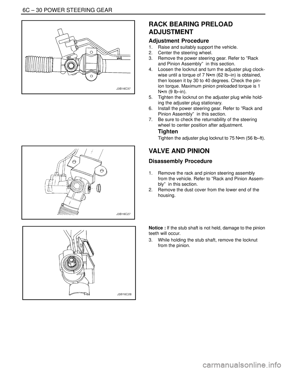
3. Remove the adjuster spring and the rack bearing.
Assembly Procedure
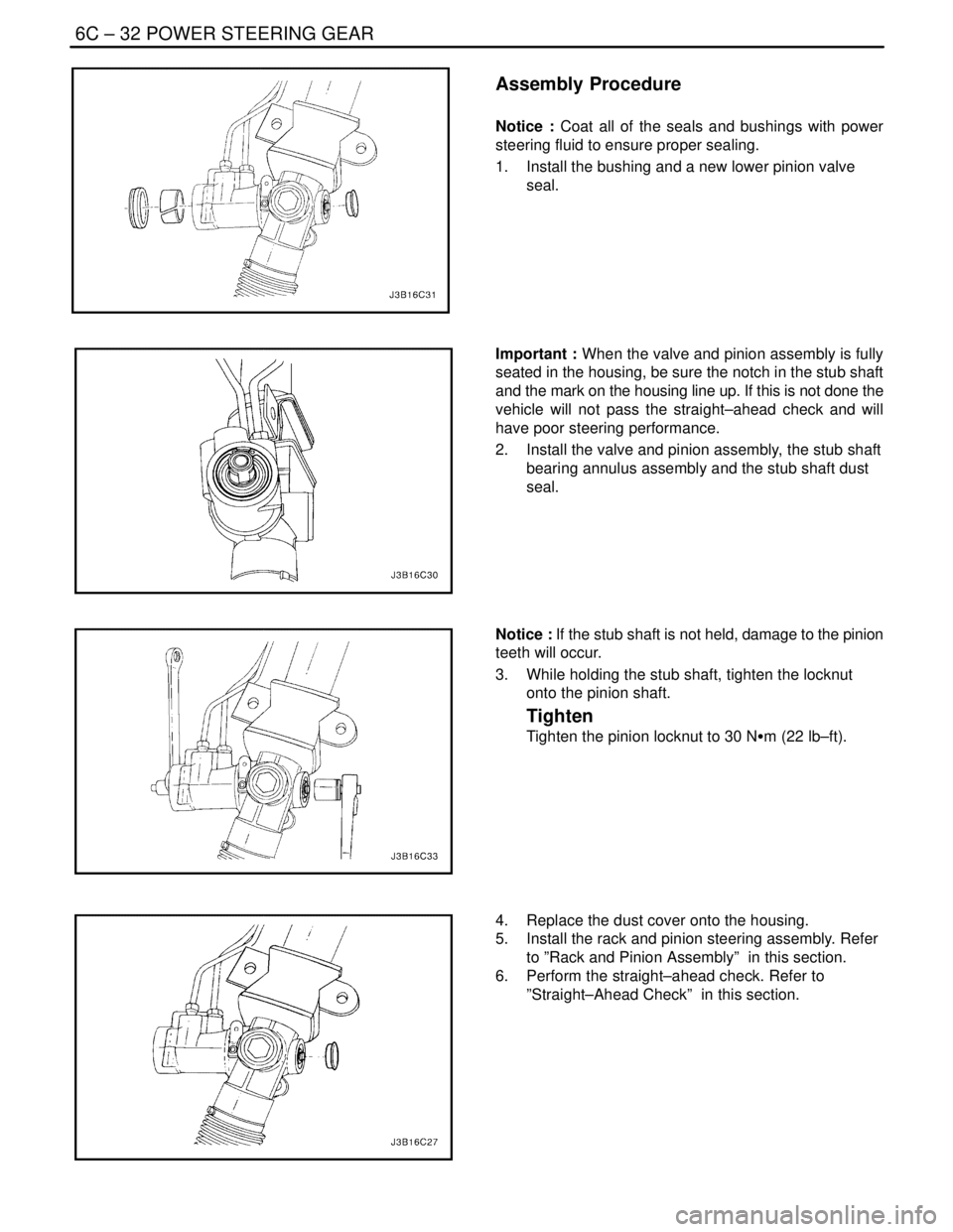
1. Coat the rack bearing, the adjuster spring and the
adjuster plug with lithium–based grease and install
them into the housing.
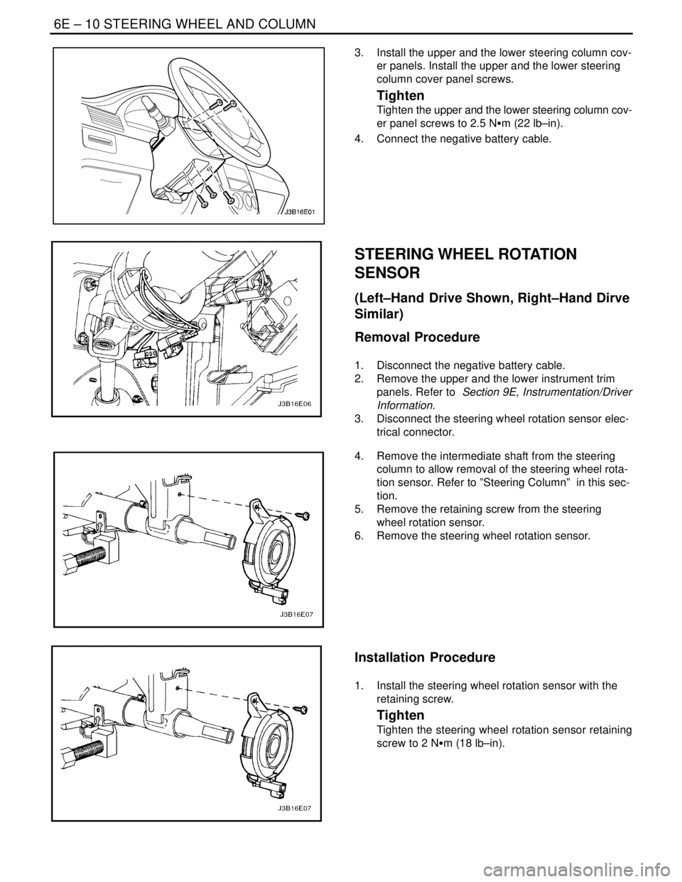
2. With the rack centered, turn the adjuster plug clock-
wise until a torque of 7 NSm (62 lb–in) is obtained,
then back it off by 30 to 40 degrees. Check the pin-
ion torque. Maximum pinion preloaded torque is 1
NSm (9 lb–in).
3. Thread the locknut on the adjuster plug and tighten
it.
Tighten
Tighten the adjuster plug locknut to 75 NSm (56 lb–ft)
while holding the adjuster plug stationary with the rack
guide spring cap wrench J–42459 or with a 19 mm al-
len wrench.
4. Install the rack and pinion assembly. Refer to ”Rack
and Pinion Assembly” in this section.
Page 1947 of 2643

6C – 30IPOWER STEERING GEAR
DAEWOO V–121 BL4
RACK BEARING PRELOAD
ADJUSTMENT
Adjustment Procedure
1. Raise and suitably support the vehicle.
2. Center the steering wheel.
3. Remove the power steering gear. Refer to ”Rack
and Pinion Assembly” in this section.
4. Loosen the locknut and turn the adjuster plug clock-
wise until a torque of 7 NSm (62 lb–in) is obtained,
then loosen it by 30 to 40 degrees. Check the pin-
ion torque. Maximum pinion preloaded torque is 1
NSm (9 lb–in).
5. Tighten the locknut on the adjuster plug while hold-
ing the adjuster plug stationary.
6. Install the power steering gear. Refer to ”Rack and
Pinion Assembly” in this section.
7. Be sure to check the returnability of the steering
wheel to center position after adjustment.
Tighten
Tighten the adjuster plug locknut to 75 NSm (56 lb–ft).
VALVE AND PINION
Disassembly Procedure
1. Remove the rack and pinion steering assembly
from the vehicle. Refer to ”Rack and Pinion Assem-
bly” in this section.
2. Remove the dust cover from the lower end of the
housing.
Notice : If the stub shaft is not held, damage to the pinion
teeth will occur.
3. While holding the stub shaft, remove the locknut
from the pinion.
Page 1949 of 2643

6C – 32IPOWER STEERING GEAR
DAEWOO V–121 BL4
Assembly Procedure
Notice : Coat all of the seals and bushings with power
steering fluid to ensure proper sealing.
1. Install the bushing and a new lower pinion valve
seal.
Important : When the valve and pinion assembly is fully
seated in the housing, be sure the notch in the stub shaft
and the mark on the housing line up. If this is not done the
vehicle will not pass the straight–ahead check and will
have poor steering performance.
2. Install the valve and pinion assembly, the stub shaft
bearing annulus assembly and the stub shaft dust
seal.
Notice : If the stub shaft is not held, damage to the pinion
teeth will occur.
3. While holding the stub shaft, tighten the locknut
onto the pinion shaft.
Tighten
Tighten the pinion locknut to 30 NSm (22 lb–ft).
4. Replace the dust cover onto the housing.
5. Install the rack and pinion steering assembly. Refer
to ”Rack and Pinion Assembly” in this section.
6. Perform the straight–ahead check. Refer to
”Straight–Ahead Check” in this section.
Page 1955 of 2643

SECTION : 6E
STEERING WHEEL AND COLUMN
CAUTION : Disconnect the negative battery cable before removing or installing any electrical unit or when a tool
or equipment could easily come in contact with exposed electrical terminals. Disconnecting this cable will help
prevent personal injury and damage to the vehicle. The ignition must also be in LOCK unless otherwise noted.
TABLE OF CONTENTS
SPECIFICATIONS6E–1 . . . . . . . . . . . . . . . . . . . . . . . . . .
Fastener Tightening Specifications 6E–1. . . . . . . . . . .
SPECIAL TOOLS6E–2 . . . . . . . . . . . . . . . . . . . . . . . . . . .
Special Tools Table 6E–2. . . . . . . . . . . . . . . . . . . . . . . .
DIAGNOSIS6E–2 . . . . . . . . . . . . . . . . . . . . . . . . . . . . . . . .
Steering Column Diagnosis 6E–2. . . . . . . . . . . . . . . . .
MAINTENANCE AND REPAIR6E–8 . . . . . . . . . . . . . . .
ON–VEHICLE SERVICE 6E–8. . . . . . . . . . . . . . . . . . . . .
Headlamp/Turn Signal Switch and Lever 6E–8. . . . . .
Wiper Switch and Lever 6E–9. . . . . . . . . . . . . . . . . . . . Steering Wheel Rotation Sensor 6E–10. . . . . . . . . . . .
Steering Wheel Without SIR 6E–11. . . . . . . . . . . . . . . .
Steering Wheel With SIR 6E–13. . . . . . . . . . . . . . . . . .
Ignition Lock Cylinder and Switch 6E–13. . . . . . . . . . .
Steering Column 6E–15. . . . . . . . . . . . . . . . . . . . . . . . . .
UNIT REPAIR 6E–19. . . . . . . . . . . . . . . . . . . . . . . . . . . . .
Tilt Steering Column 6E–19. . . . . . . . . . . . . . . . . . . . . .
GENERAL DESCRIPTION AND SYSTEM
OPERATION6E–20 . . . . . . . . . . . . . . . . . . . . . . . . . . . . .
Steering Wheel and Column 6E–20. . . . . . . . . . . . . . . .
Ignition Key Reminder 6E–20. . . . . . . . . . . . . . . . . . . . .
SPECIFICATIONS
FASTENER TIGHTENING SPECIFICATIONS
ApplicationNSmLb–FtLb–In
Ignition Switch Housing Shear Bolts11–97
Ignition Switch Retaining Screw2.5–22
Steering Column Jacket Assembly Front Bracket Bolts2216–
Steering Column Jacket Assembly Rear Bracket Nuts2216–
Steering Shaft Universal Joint Pinch Bolt2518–
Steering Wheel Horn Cap Screws4.5–40
Steering Wheel Nut3828–
Steering Wheel Rotation Sensor Retaining Screw2–18
Support Housing Screws1612–
Turn Signal Switch Housing Screws3–27
Upper and Lower Steering Column Cover Panel Screws2.5–22
Page 1964 of 2643

6E – 10ISTEERING WHEEL AND COLUMN
DAEWOO V–121 BL4
3. Install the upper and the lower steering column cov-
er panels. Install the upper and the lower steering
column cover panel screws.
Tighten
Tighten the upper and the lower steering column cov-
er panel screws to 2.5 NSm (22 lb–in).
4. Connect the negative battery cable.
STEERING WHEEL ROTATION
SENSOR
(Left–Hand Drive Shown, Right–Hand Dirve
Similar)
Removal Procedure
1. Disconnect the negative battery cable.
2. Remove the upper and the lower instrument trim
panels. Refer to Section 9E, Instrumentation/Driver
Information.
3. Disconnect the steering wheel rotation sensor elec-
trical connector.
4. Remove the intermediate shaft from the steering
column to allow removal of the steering wheel rota-
tion sensor. Refer to ”Steering Column” in this sec-
tion.
5. Remove the retaining screw from the steering
wheel rotation sensor.
6. Remove the steering wheel rotation sensor.
Installation Procedure
1. Install the steering wheel rotation sensor with the
retaining screw.
Tighten
Tighten the steering wheel rotation sensor retaining
screw to 2 NSm (18 lb–in).