Page 2319 of 2643
9E – 20IINSTRUMENTATION/DRIVER INFORMATION
DAEWOO V–121 BL4
Installation Procedure
1. Install the ashtray housing with screws.
2. Install the instrument panel center molding.
CIGAR LIGHTER
Removal Procedure
1. Remove the instrument panel center molding.
2. Disconnect the cigar lighter and ashtray lamp elec-
trical connector.
3. Remove the cigar lighter housing from the instru-
ment panel.
Installation Procedure
1. Install the cigar lighter housing to the instrument
panel.
2. Install the cigar lighter in the cigar lighter housing.
3. Connect the cigar lighter and ashtray lamp electri-
cal connector.
4. Install the instrument panel center molding.
GLOVE BOX
Removal Procedure
1. Remove the screws and the glove box.
Page 2320 of 2643
INSTRUMENTATION/DRIVER INFORMATION 9E – 21
DAEWOO V–121 BL4
Installation Procedure
1. Install the glove box with the screws.
NOTCHBACK DEPOSIT BOX
Removal Procedure
1. Remove the glove box.
2. Remove the screws and deposit box.
Installation Procedure
1. Install the deposit box with the screws.
2. Install the glove box.
NOTCHBACK DIGITAL CLOCK
Removal Procedure
1. Disconnect the negative battery cable.
2. Remove the center molding.
3. Disconnect the electrical connector.
4. Remove the screws and digital clock.
Page 2321 of 2643
9E – 22IINSTRUMENTATION/DRIVER INFORMATION
DAEWOO V–121 BL4
Installation Procedure
1. Install the digital clock with the screws.
2. Connect the electrical connector.
3. Install the center molding.
4. Connect the negative battery cable.
HATCHBACK DIGITAL CLOCK
Removal Procedure
1. Disconnect the negative battery cable.
2. Remove the instrument panel center upper cover.
3. Remove the screws and the clock.
Installation Procedure
1. Install the clock with the screws.
Tighten
Tighten the clock screws to 3 NSm (27 lb–in).
2. Install the instrument panel center upper cover.
3. Connect the negative battery cable.
Page 2322 of 2643
INSTRUMENTATION/DRIVER INFORMATION 9E – 23
DAEWOO V–121 BL4
INSTRUMENT CLUSTER
Removal Procedure
1. Disconnect the negative battery cable.
2. Remove the instrument cluster trim panel.
3. Remove the screws and the instrument cluster.
4. Disconnect the electrical connectors.
Installation Procedure
1. Connect the electrical connectors.
2. Install the instrument cluster with the screws.
Tighten
Tighten the instrument cluster screw to 4 NSm (35 lb–
in).
3. Install the instrument cluster trim panel.
4. Connect the negative battery cable.
INSTRUMENT CLUSTER DIMMER
SWITCH
Removal Procedure
1. Remove the instrument cluster dimmer switch as-
sembly.
2. Disconnect the electrical connectors.
Page 2323 of 2643

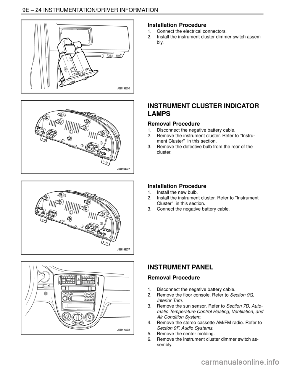
9E – 24IINSTRUMENTATION/DRIVER INFORMATION
DAEWOO V–121 BL4
Installation Procedure
1. Connect the electrical connectors.
2. Install the instrument cluster dimmer switch assem-
bly.
INSTRUMENT CLUSTER INDICATOR
LAMPS
Removal Procedure
1. Disconnect the negative battery cable.
2. Remove the instrument cluster. Refer to ”Instru-
ment Cluster” in this section.
3. Remove the defective bulb from the rear of the
cluster.
Installation Procedure
1. Install the new bulb.
2. Install the instrument cluster. Refer to ”Instrument
Cluster” in this section.
3. Connect the negative battery cable.
INSTRUMENT PANEL
Removal Procedure
1. Disconnect the negative battery cable.
2. Remove the floor console. Refer to Section 9G,
Interior Trim.
3. Remove the sun sensor. Refer to Section 7D, Auto-
matic Temperature Control Heating, Ventilation, and
Air Condition System.
4. Remove the stereo cassette AM/FM radio. Refer to
Section 9F, Audio Systems.
5. Remove the center molding.
6. Remove the instrument cluster dimmer switch as-
sembly.
Page 2324 of 2643
INSTRUMENTATION/DRIVER INFORMATION 9E – 25
DAEWOO V–121 BL4
7. Remove the instrument cluster trim panel. Refer to
”Instrument Cluster Trim Panel” in this section.
8. Remove the instrument cluster. Refer to ”Instru-
ment Cluster” in this section.
9. Remove the glove box and the glove box housing.
Refer to ”Glove Box” in this section.
10. Remove the knee bolster. Refer to Section 9G, In-
terior Trim.
11. Remove the screws and the instrument panel side
covers.
12. Remove the screw and the instrument panel fuse
block.
13. Remove the nuts and the bolts securing the steer-
ing column.
14. Disconnect the steering column electrical connec-
tor.
15. Lower the steering column.
16. Remove bolts and screws.
17. Remove the connecting pieces.
Page 2325 of 2643
9E – 26IINSTRUMENTATION/DRIVER INFORMATION
DAEWOO V–121 BL4
18. Remove the bolt securing the middle of the instru-
ment panel to the body.
19. Remove the instrument panel screws behind the
glove box brace.
20. Remove the bolts securing the sides of the instru-
ment panel to body.
21. Disconnect the instrument panel electrical connec-
tors.
22. Remove the instrument panel.
Installation Procedure
1. Position the instrument panel in the vehicle.
2. Connect the instrument panel electrical connectors.
Notice : Dissimilar metals in direct contact with each other
may corrode rapidly. Make sure to use the correct fasten-
ers to prevent premature corrosion.
3. Install the bolts securing the sides of the instrument
panel to the body.
Tighten
Tighten the instrument panel–to–body bolts to 22
NSm (16 lb–ft).
Page 2326 of 2643
INSTRUMENTATION/DRIVER INFORMATION 9E – 27
DAEWOO V–121 BL4
4. Install the instrument panel screws behind the glove
box brace.
5. Install the bolt securing the middle of the instrument
panel to the body.
Tighten
Tighten the instrument panel–to–body bolts to 22
NSm (16 lb–ft).
6. Install the connecting pieces with bolts and screws.
Tighten
Tighten the connecting pieces bolts to 22 NSm (16 lb–
ft).
7. Raise the steering column.
8. Connect the steering column electrical connector.
9. Install the nuts and the bolts securing the steering
column.
Tighten
Tighten the steering column nuts to 22 NSm (16 lb–ft).
Tighten the steering column bolts to 22 NSm (16 lb–ft).