2004 DAEWOO LACETTI driver
[x] Cancel search: driverPage 2327 of 2643
9E – 28IINSTRUMENTATION/DRIVER INFORMATION
DAEWOO V–121 BL4
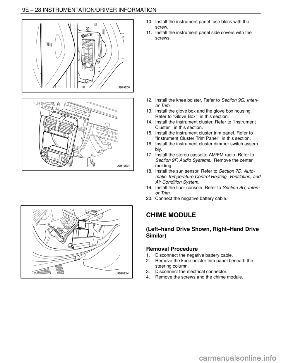
10. Install the instrument panel fuse block with the
screw.
11. Install the instrument panel side covers with the
screws.
12. Install the knee bolster. Refer to Section 9G, Interi-
or Trim.
13. Install the glove box and the glove box housing.
Refer to ”Glove Box” in this section.
14. Install the instrument cluster. Refer to ”Instrument
Cluster” in this section.
15. Install the instrument cluster trim panel. Refer to
”Instrument Cluster Trim Panel” in this section.
16. Install the instrument cluster dimmer switch assem-
bly.
17. Install the stereo cassette AM/FM radio. Refer to
Section 9F, Audio Systems. Remove the center
molding.
18. Install the sun sensor. Refer to Section 7D, Auto-
matic Temperature Control Heating, Ventilation, and
Air Condition System.
19. Install the floor console. Refer to Section 9G, Interi-
or Trim.
20. Connect the negative battery cable.
CHIME MODULE
(Left–hand Drive Shown, Right–Hand Drive
Similar)
Removal Procedure
1. Disconnect the negative battery cable.
2. Remove the knee bolster trim panel beneath the
steering column.
3. Disconnect the electrical connector.
4. Remove the screws and the chime module.
Page 2328 of 2643
INSTRUMENTATION/DRIVER INFORMATION 9E – 29
DAEWOO V–121 BL4
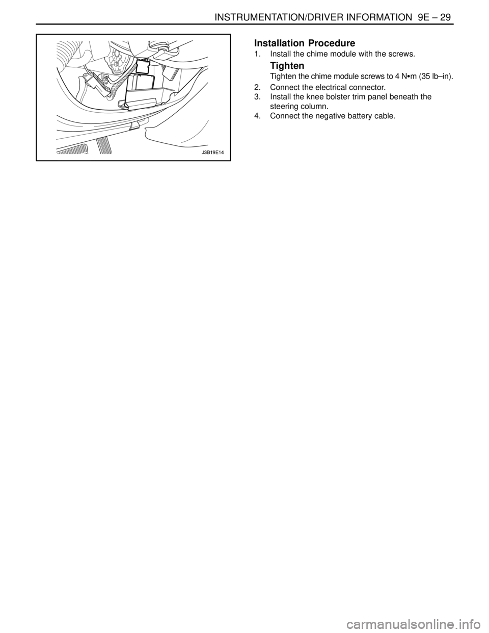
Installation Procedure
1. Install the chime module with the screws.
Tighten
Tighten the chime module screws to 4 NSm (35 lb–in).
2. Connect the electrical connector.
3. Install the knee bolster trim panel beneath the
steering column.
4. Connect the negative battery cable.
Page 2329 of 2643

9E – 30IINSTRUMENTATION/DRIVER INFORMATION
DAEWOO V–121 BL4
GENERAL DESCRIPTION
AND SYSTEM OPERATION
CIGAR LIGHTER
The cigar lighter is located in the front portion of the floor
console. To use the lighter, push it in completely. When the
lighter is hot, it will release itself from contact with the heat-
ing element. The lighter and the heating element can be
damaged if the lighter is not allowed to release itself fully
from the heating element.
ASHTRAY
The ashtray is located below the audio system. To access
the ashtray, pull it out from the center console. The ashtray
lamp will go on when the parking lamps or the headlamps
are turned on.
INSTRUMENT PANEL VENTS
The center and the side vents in the instrument panel can
be adjusted up and down and from side to side. The side
vents can also be aimed toward the side windows in order
to defog them.
GLOVE BOX
The glove box can be opened by pulling up on the latch
handle. The glove box must be removed in order to gain
access to the passenger’s side airbag module.
DIGTAL CLOCK
The digital clock is located in the instrument panel, above
the audio system. The clock is capable of a 12–hour or a
24–hour display.
INSTRUMENT CLUSTER
The instrument cluster is located above the steering col-
umn and in the instrument cluster trim panel. The instru-
ment cluster contains the instruments that provide the
driver with vehicle performance information. The instru-
ment cluster contains a speedometer, an odometer, a trip
odometer, a temperature gauge, a fuel gauge, and several
indicator lamps. For replacement of the indicator lamp
bulbs contained in the instrument cluster, refer to ”Instru-
ment Cluster Indicator Lamps Specifications” and”Instru-
ment Cluster Indicator Lamps” in this section.
SPEEDOMETER/ODOMETER/TRIP
ODOMETER
The speedometer measures the speed of the vehicle in
km/h (mph in some countries). It consists of an instrument
cluster gauge connected to the vehicle speed sensor
(VSS) on the transaxle output shaft.The odometer measures in kilometers (miles in some
countries) the total distance the vehicle has traveled since
it was manufactured. It consists of an instrument cluster
gauge connected to the VSS on the transaxle output shaft.
The trip odometer measures the distance the vehicle has
traveled since the odometer was last reset. It consists of
an instrument cluster gauge connected to the VSS on the
transaxle output shaft. The trip odometer can be reset to
zero at any time so that the driver can record the distance
traveled from any starting point.
FUEL GAUGE
The fuel gauge consists of an instrument cluster gauge
connected to a sending unit in the fuel tank.
The fuel gauge indicates the quantity of fuel in the tank
only when the ignition switch is turned to ON or ACC.
When the ignition is turned to LOCK or START, the pointer
may come to rest at any position.
TEMPERATURE GAUGE
The temperature gauge consists of an instrument cluster
gauge connected to a temperature sensor that is in con-
tact with the circulating engine coolant.
The temperature gauge indicates the temperature of the
coolant. Prolonged driving or idling in very hot weather
may cause the pointer to move beyond the center of the
gauge. The engine is overheating if the pointer moves into
the red zone at the upper limit of the gauge.
INSTRUMENT CLUSTER INDICATOR
LAMPS
The instrument cluster contains indicator lamps that indi-
cate the functioning of certain systems or the existence of
potential problems with the operation of the vehicle. The
indicator lamps are replaceable. For replacement of the in-
dicator lamps contained in the instrument cluster, refer to
”Instrument Cluster Indicator Lamps Specifications”
and”Instrument Cluster Indicator Lamps” in this section.
CHIME MODULE
The chime module is located above the instrument panel
fuse block and will sound in order to bring attention to one
or more of the following conditions:
S The lamps are on, the door is ajar, and the ignition
switch is not in ACC, ON, or START.
S The seat belt is unbuckled when the ignition switch
is in ON or START.
S The door is open when the ignition switch is in ON
or START.
S The key is left in the ignition switch when the igni-
tion is in LOCK and the door is open.
Page 2341 of 2643

SECTION : 9G
INTERIOR TRIM
CAUTION : Disconnect the negative battery cable before removing or installing any electrical unit or when a tool
or equipment could easily come in contact with exposed electrical terminals. Disconnecting this cable will help
prevent personal injury and damage to the vehicle. The ignition must also be in LOCK unless otherwise noted.
TABLE OF CONTENTS
SPECIFICATIONS9G–1 . . . . . . . . . . . . . . . . . . . . . . . . . .
Fastener Tightening Specifications 9G–1. . . . . . . . . . .
SPECIAL TOOLS9G–2 . . . . . . . . . . . . . . . . . . . . . . . . . . .
Special Tools Table 9G–2. . . . . . . . . . . . . . . . . . . . . . . .
MAINTENANCE AND REPAIR9G–3 . . . . . . . . . . . . . . .
ON–VEHICLE SERVICE 9G–3. . . . . . . . . . . . . . . . . . . . .
Front Door Trim Panel 9G–3. . . . . . . . . . . . . . . . . . . . . .
Rear Door Trim Panel 9G–4. . . . . . . . . . . . . . . . . . . . . .
A–pillar Trim Panel 9G–4. . . . . . . . . . . . . . . . . . . . . . . . .
Upper B–pillar Trim Panel 9G–5. . . . . . . . . . . . . . . . . . .
Lower B–pillar Trim Panel 9G–5. . . . . . . . . . . . . . . . . . .
C–pillar Trim Panel 9G–6. . . . . . . . . . . . . . . . . . . . . . . . .
Deck Lid Sill Plate Cover 9G–6. . . . . . . . . . . . . . . . . . .
Front Rocker Trim Panel 9G–7. . . . . . . . . . . . . . . . . . . .
Rear Rocker Trim Panel 9G–7. . . . . . . . . . . . . . . . . . . .
Front Wheelhouse Trim 9G–8. . . . . . . . . . . . . . . . . . . . .
Rear Wheelhouse Trim 9G–8. . . . . . . . . . . . . . . . . . . . .
Floor Console 9G–9. . . . . . . . . . . . . . . . . . . . . . . . . . . . . Floor Carpet 9G–10. . . . . . . . . . . . . . . . . . . . . . . . . . . . .
Luggage Compartment Rear Low Cover 9G–11. . . . .
Luggage Compartment Wheelhouse Trim
Panel 9G–12. . . . . . . . . . . . . . . . . . . . . . . . . . . . . . . . . .
Driver’s Side Knee Bolster 9G–12. . . . . . . . . . . . . . . . .
Hatchback Door Lower Garnish Molding 9G–13. . . . .
Hatchback Door Upper Garnish Molding 9G–14. . . . .
Luggage Compartment Wheelhouse Trim Panel
(HATCHBACK) 9G–14. . . . . . . . . . . . . . . . . . . . . . . . .
Luggage Compartment Rear Trim Panel 9G–14. . . . .
GENERAL DESCRIPTION AND SYSTEM
OPERATION9G–16 . . . . . . . . . . . . . . . . . . . . . . . . . . . . .
Interior Trim Panels 9G–16. . . . . . . . . . . . . . . . . . . . . . .
Pressure Relief Vent 9G–16. . . . . . . . . . . . . . . . . . . . . .
Floor Console 9G–16. . . . . . . . . . . . . . . . . . . . . . . . . . . .
Floor Carpet 9G–16. . . . . . . . . . . . . . . . . . . . . . . . . . . . .
Rear Compartment Security Cover
(HATCHBACK) 9G–16. . . . . . . . . . . . . . . . . . . . . . . . .
SPECIFICATIONS
FASTENER TIGHTENING SPECIFICATIONS
ApplicationNSmLb–FtLb–In
Door Trim Panel Screws2.5–22
Driver’s Side Knee Bolster Mounting Bolts10–89
Floor Console Screws2.5–22
Gearshift Housing Bolts8–70
Hood Latch Release Handle Mounting Screw3–27
Seat Belt Anchor Bolt3828–
Page 2352 of 2643
9G – 12IINTERIOR TRIM
DAEWOO V–121 BL4
LUGGAGE COMPARTMENT
WHEELHOUSE TRIM PANEL
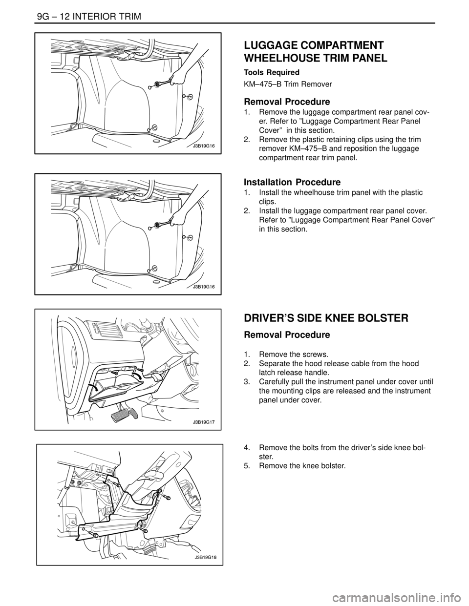
Tools Required
KM–475–B Trim Remover
Removal Procedure
1. Remove the luggage compartment rear panel cov-
er. Refer to ”Luggage Compartment Rear Panel
Cover” in this section.
2. Remove the plastic retaining clips using the trim
remover KM–475–B and reposition the luggage
compartment rear trim panel.
Installation Procedure
1. Install the wheelhouse trim panel with the plastic
clips.
2. Install the luggage compartment rear panel cover.
Refer to ”Luggage Compartment Rear Panel Cover”
in this section.
DRIVER’S SIDE KNEE BOLSTER
Removal Procedure
1. Remove the screws.
2. Separate the hood release cable from the hood
latch release handle.
3. Carefully pull the instrument panel under cover until
the mounting clips are released and the instrument
panel under cover.
4. Remove the bolts from the driver’s side knee bol-
ster.
5. Remove the knee bolster.
Page 2353 of 2643
INTERIOR TRIM 9G – 13
DAEWOO V–121 BL4
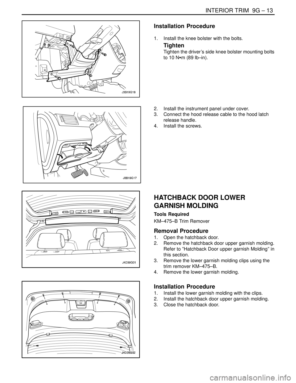
Installation Procedure
1. Install the knee bolster with the bolts.
Tighten
Tighten the driver’s side knee bolster mounting bolts
to 10 NSm (89 lb–in).
2. Install the instrument panel under cover.
3. Connect the hood release cable to the hood latch
release handle.
4. Install the screws.
HATCHBACK DOOR LOWER
GARNISH MOLDING
Tools Required
KM–475–B Trim Remover
Removal Procedure
1. Open the hatchback door.
2. Remove the hatchback door upper garnish molding.
Refer to ”Hatchback Door upper garnish Molding” in
this section.
3. Remove the lower garnish molding clips using the
trim remover KM–475–B.
4. Remove the lower garnish molding.
Installation Procedure
1. Install the lower garnish molding with the clips.
2. Install the hatchback door upper garnish molding.
3. Close the hatchback door.
Page 2363 of 2643
SEATS 9H – 7
DAEWOO V–121 BL4
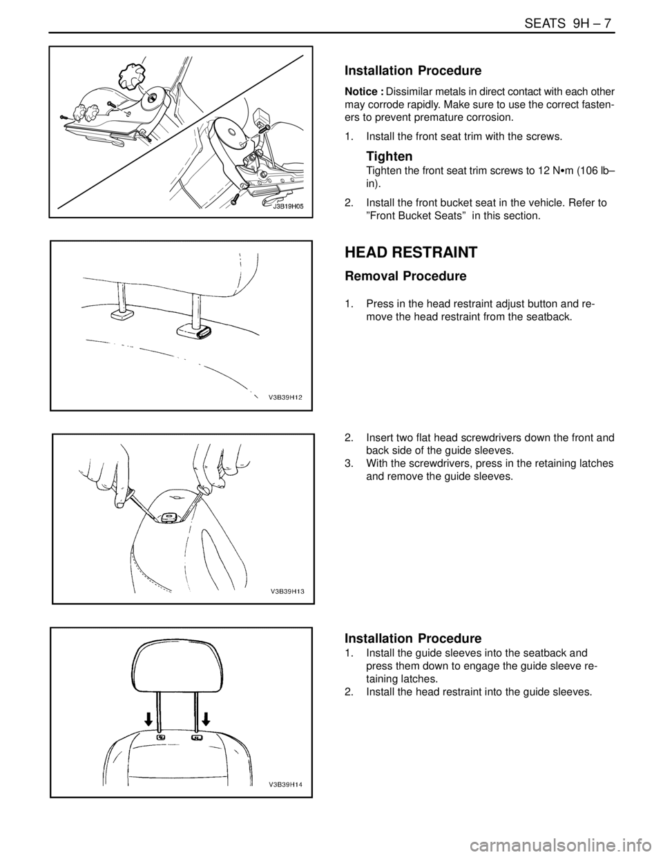
Installation Procedure
Notice : Dissimilar metals in direct contact with each other
may corrode rapidly. Make sure to use the correct fasten-
ers to prevent premature corrosion.
1. Install the front seat trim with the screws.
Tighten
Tighten the front seat trim screws to 12 NSm (106 lb–
in).
2. Install the front bucket seat in the vehicle. Refer to
”Front Bucket Seats” in this section.
HEAD RESTRAINT
Removal Procedure
1. Press in the head restraint adjust button and re-
move the head restraint from the seatback.
2. Insert two flat head screwdrivers down the front and
back side of the guide sleeves.
3. With the screwdrivers, press in the retaining latches
and remove the guide sleeves.
Installation Procedure
1. Install the guide sleeves into the seatback and
press them down to engage the guide sleeve re-
taining latches.
2. Install the head restraint into the guide sleeves.
Page 2368 of 2643

9H – 12ISEATS
DAEWOO V–121 BL4
GENERAL DESCRIPTION
AND SYSTEM OPERATION
SEATS
Do not attempt to change the designed seat position by al-
tering the designed seat adjuster–to–floor pan anchor pro-
visions or the seat adjuster–to–seat frame anchor provi-
sions. Changing the seat position could affect the
performance of the seat system.This vehicle is equipped with front bucket seats with sepa-
rate, adjustable head restraints, and a three–passenger
rear bench seat with an optional split folding rear seat. The
front bucket seats also have a recline, a height, and a lum-
bar adjustment. A power driver seat is optional. Seat cush-
ions and seatbacks have formed foam pads, which fit the
contours of the full panel seatback frame assembly and
the designed contour of the seat cushion frame.