2004 DAEWOO LACETTI driver
[x] Cancel search: driverPage 2375 of 2643
SECTION : 9J
WINDNOISE
TABLE OF CONTENTS
DIAGNOSIS9J–1 . . . . . . . . . . . . . . . . . . . . . . . . . . . . . . . . .
Windnoise Diagnosis 9J–1. . . . . . . . . . . . . . . . . . . . . . . .
MAINTENANCE AND REPAIR9J–2 . . . . . . . . . . . . . . . . ON–VEHICLE SERVICE 9J–2. . . . . . . . . . . . . . . . . . . . . .
Windnoise Repair 9J–2. . . . . . . . . . . . . . . . . . . . . . . . . . .
DIAGNOSIS
WINDNOISE DIAGNOSIS
CAUTION : An assistant should drive the vehicle
while the technician checks for the location of the
windnoise, in order to prevent personal injury or ve-
hicle damage.
A test drive in the vehicle is necessary to accurately deter-
mine the location of the windnoise. Often there is a primary
leak and secondary leaks. Failure to repair all leaks will
only reduce the windnoise, not eliminate it.
During the test drive the technician should bring the follow-
ing items to aid in determining the location of the wind-
noise.
S A mechanics stethoscope or vacuum hose
S Masking tape
S Strip caulk
S A china marking pencil
S A screwdriver
Perform the following steps in order to conduct the road
test:
1. Choose a route that includes smooth straight
streets that run in all four directions (north, south,
east, and west).
2. Choose streets with little traffic or noise that would
interfere with the test.
3. Drive the vehicle at the speeds at which the noise
was noticed by the customer or until the noise is
produced. Do not exceed legal speed limits.
4. The windnoise is external if any of the following
conditions occur:
S The windnoise is caused by the wind.S The windnoise can be heard with the door glass
lowered and while the vehicle is being driven.
S The windnoise is eliminated when tape is placed
over various moldings and gaps.
5. Internal windnoise is air leaving the vehicle and
should be repaired in the following manner.
S In order to locate the leak, tape off the body lock
pillar pressure relief valves. This will cause air
pressure to build up inside the vehicle and en-
hance the windnoise.
S Use a stethoscope or a vacuum hose to locate
the leak.
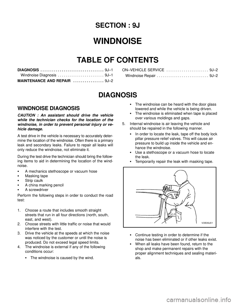
S Temporarily repair the leak with masking tape.
S Continue testing in order to determine if the
noise has been eliminated or if other leaks exist.
S When all leaks have been found, return to the
shop and make permanent repairs with the
proper alignment techniques and sealing materi-
als.
Page 2386 of 2643

GLASS AND MIRRORS 9L – 7
DAEWOO V–121 BL4
StepNo Yes Value(s) Action
101. Turn the ignition ON.
2. Check the voltage at terminal 8 (BRN) of the
electric control outside rearview mirror switch
connector.
Is the voltage equal to the specified value?11–14 vGo to Step 12 Go to Step 11
11Repair the open power supply circuit for the electric
control outside rearview mirror switch.
Is the repair complete?–System OK–
12Replace the electric control outside rearview mirror
switch.
Is the repair complete?–System OK–
131. On the side which has the inoperative mirror,
remove the black plastic escutcheon from the
trim panel side of the door.
2. Disconnect the electric control outside rearview
mirror electrical connector.
3. Turn the ignition ON.
4. At the electric control outside rearview mirror
connector, connect a voltmeter between termi-
nal 4 (GRY) and terminal 6 (LT GRN if testing
the driver side or PPL/WHT if testing the pas-
senger side).
5. Operate the in/out adjustment on the switch,
and record the voltage indicated in each switch
position.
6. Connect a voltmeter between terminal 4 (GRY)
and terminal 7 (LT GRN if testing the left side
or RED/WHT if testing the right side).
7. Operate the up/down adjustment on the switch,
and record the voltage indicated in each switch
position.
Does the voltmeter indicate the specified voltage for
each test, with the polarity reversing when the switch
is changed from in to out or up to down?11–14 vGo to Step 14 Go to Step 15
14Replace the electric control outside rearview mirror.
Is the repair complete?–System OK–
Page 2398 of 2643

GLASS AND MIRRORS 9L – 19
DAEWOO V–121 BL4
GENERAL DESCRIPTION
AND SYSTEM OPERATION
STATIONARY GLASS
Stationary glass consists of all the glass on the vehicle
which is immovable within its frame, such as the wind-
shield glass, the back glass, and the inside rearview mir-
ror.
ELECTRIC CONTROL HEATED
OUTSIDE REARVIEW MIRROR
The electric control for the heated outside rearview mirroris on the driver’s side door. The mirror defogger is acti-
vated by the rear window defogger switch.
INSIDE REARVIEW MIRROR
The rearview mirror pivots at the ball–and–socket mirror
pivot and can be manually adjusted up/down and left/right.
FOLDING MIRROR UNIT
The folding mirror system is automatically folding the mir-
ror in parking state.
Page 2449 of 2643

DOORS 9P – 29
DAEWOO V–121 BL4
GENERAL DESCRIPTION
AND SYSTEM OPERATION
DOOR LOCK STRIKER
The front and the rear door lock strikers each consist of a
striker with two screws threaded into a floating cage plate
in the B–pillars and the C–pillars. The door is secured in
the closed position when the door lock fork snaps over and
engages the striker.
CHILDPROOF REAR DOOR LOCK
The childproof rear door locks help prevent passengers,
especially children, from opening the rear doors of the ve-
hicle from the inside.
To activate the locks, move the levers of both rear doors
to the lock position. Then, close both doors. The rear pas-
sengers will be unable to open the doors from inside of the
vehicle.
To deactivate the locks, unlock the door from the inside of
the vehicle and open the door from the outside. Move the
lever to the unlock position. The rear door will now work
normally.
POWER DOOR LOCKS
The power door locks use a solenoid that is contained in
each door lock assembly. The door locks are activated by
the actuator on the inside door handle or by the lock cylin-
der on the driver’s side door only. When the driver’s side
door is locked or unlocked by the actuator or the lock cylin-
der, all doors are locked or unlocked accordingly.
POWER WINDOWS
The power windows are controlled by electrical switches
on the door panels and are operated by a motor at each
window regulator. Each door has a switch to control its
window, and the driver’s side door has four switches to
control all door windows on the vehicle. The windows are
lowered by pressing the switch and raised by pulling up on
the switch. The window will stop movement when the
switch is released or when the window is completely open
or closed.
The driver’s side window opens automatically. By pressing
and releasing the switch, the driver ’s side window will low-
er and will stop only when the switch is activated again, or
when the window is completely open.
The driver’s side door control also contains a window lock
button that will prevent the operation of the front passen-
ger door or the rear door windows when pressed.
Page 2457 of 2643
9Q – 8IROOF
DAEWOO V–121 BL4
Installation Procedure
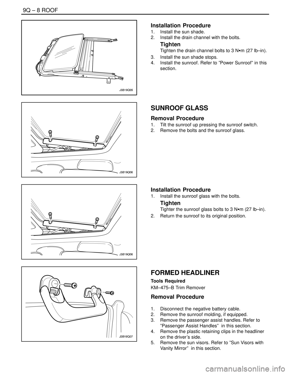
1. Install the sun shade.
2. Install the drain channel with the bolts.
Tighten
Tighten the drain channel bolts to 3 NSm (27 lb–in).
3. Install the sun shade stops.
4. Install the sunroof. Refer to ”Power Sunroof” in this
section.
SUNROOF GLASS
Removal Procedure
1. Tilt the sunroof up pressing the sunroof switch.
2. Remove the bolts and the sunroof glass.
Installation Procedure
1. Install the sunroof glass with the bolts.
Tighten
Tighter the sunroof glass bolts to 3 NSm (27 lb–in).
2. Return the sunroof to its original position.
FORMED HEADLINER
Tools Required
KM–475–B Trim Remover
Removal Procedure
1. Disconnect the negative battery cable.
2. Remove the sunroof molding, if equipped.
3. Remove the passenger assist handles. Refer to
”Passenger Assist Handles” in this section.
4. Remove the plastic retaining clips in the headliner
on the driver’s side.
5. Remove the sun visors. Refer to ”Sun Visors with
Vanity Mirror” in this section.
Page 2458 of 2643
ROOF 9Q – 9
DAEWOO V–121 BL4
6. Remove the power sunroof control switch, if
equipped. Refer to ”Power Sunroof Control Switch”
in this section.
7. Remove the A–, B–, and C–pillar trim panels. Refer
to Section 9G, Interior Trim.
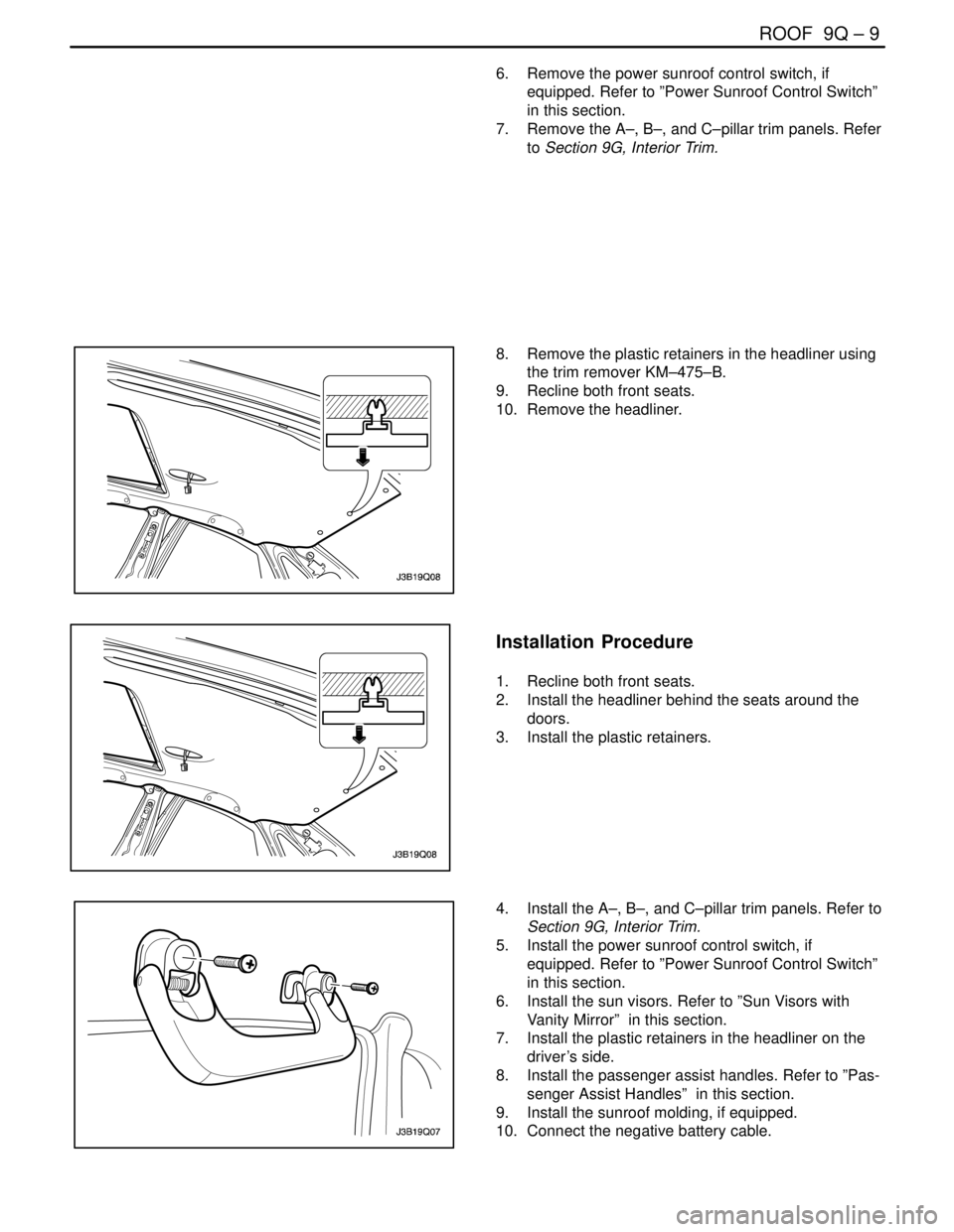
8. Remove the plastic retainers in the headliner using
the trim remover KM–475–B.
9. Recline both front seats.
10. Remove the headliner.
Installation Procedure
1. Recline both front seats.
2. Install the headliner behind the seats around the
doors.
3. Install the plastic retainers.
4. Install the A–, B–, and C–pillar trim panels. Refer to
Section 9G, Interior Trim.
5. Install the power sunroof control switch, if
equipped. Refer to ”Power Sunroof Control Switch”
in this section.
6. Install the sun visors. Refer to ”Sun Visors with
Vanity Mirror” in this section.
7. Install the plastic retainers in the headliner on the
driver’s side.
8. Install the passenger assist handles. Refer to ”Pas-
senger Assist Handles” in this section.
9. Install the sunroof molding, if equipped.
10. Connect the negative battery cable.
Page 2467 of 2643
9R – 6IBODY FRONT END
DAEWOO V–121 BL4
Installation Procedure
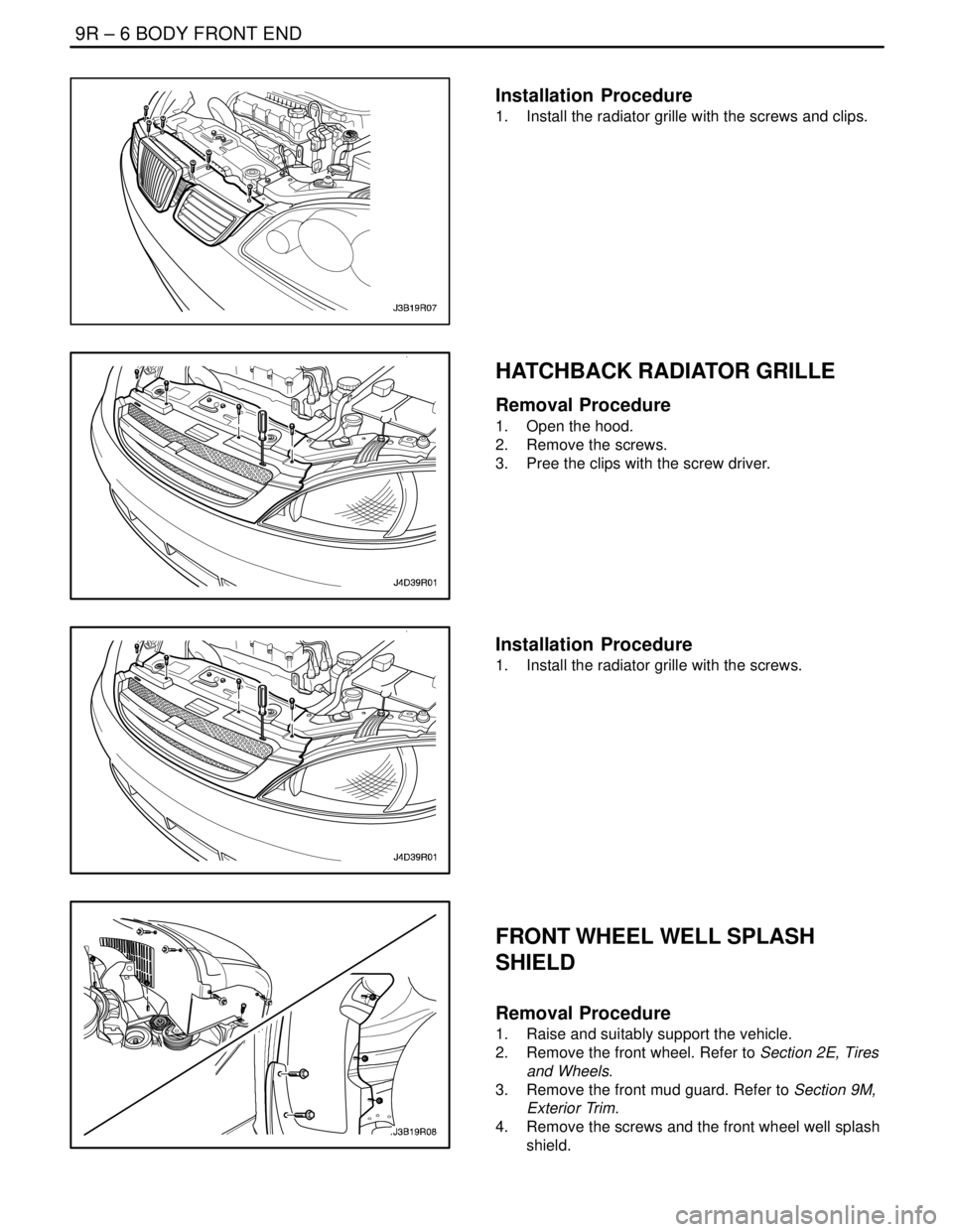
1. Install the radiator grille with the screws and clips.
HATCHBACK RADIATOR GRILLE
Removal Procedure
1. Open the hood.
2. Remove the screws.
3. Pree the clips with the screw driver.
Installation Procedure
1. Install the radiator grille with the screws.
FRONT WHEEL WELL SPLASH
SHIELD
Removal Procedure
1. Raise and suitably support the vehicle.
2. Remove the front wheel. Refer to Section 2E, Tires
and Wheels.
3. Remove the front mud guard. Refer to Section 9M,
Exterior Trim.
4. Remove the screws and the front wheel well splash
shield.
Page 2474 of 2643
BODY REAR END 9S – 3
DAEWOO V–121 BL4
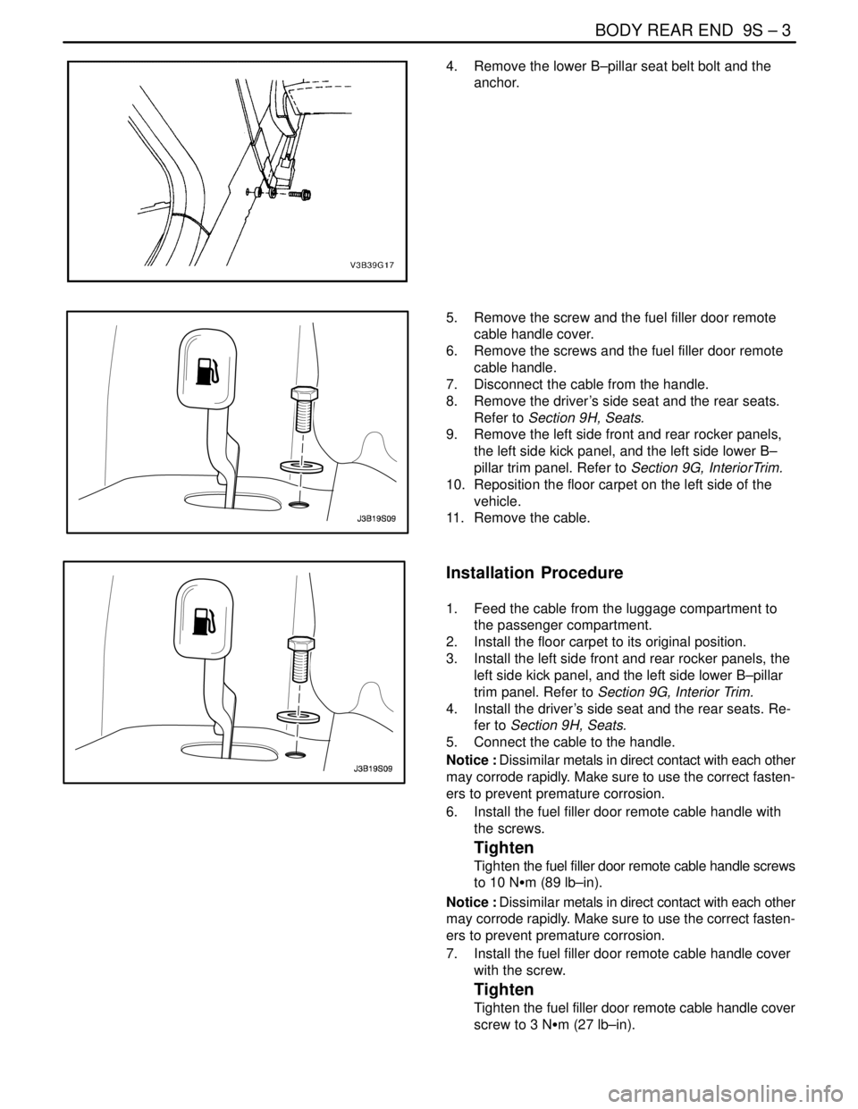
4. Remove the lower B–pillar seat belt bolt and the
anchor.
5. Remove the screw and the fuel filler door remote
cable handle cover.
6. Remove the screws and the fuel filler door remote
cable handle.
7. Disconnect the cable from the handle.
8. Remove the driver’s side seat and the rear seats.
Refer to Section 9H, Seats.
9. Remove the left side front and rear rocker panels,
the left side kick panel, and the left side lower B–
pillar trim panel. Refer to Section 9G, InteriorTrim.
10. Reposition the floor carpet on the left side of the
vehicle.
11. Remove the cable.
Installation Procedure
1. Feed the cable from the luggage compartment to
the passenger compartment.
2. Install the floor carpet to its original position.
3. Install the left side front and rear rocker panels, the
left side kick panel, and the left side lower B–pillar
trim panel. Refer to Section 9G, Interior Trim.
4. Install the driver’s side seat and the rear seats. Re-
fer to Section 9H, Seats.
5. Connect the cable to the handle.
Notice : Dissimilar metals in direct contact with each other
may corrode rapidly. Make sure to use the correct fasten-
ers to prevent premature corrosion.
6. Install the fuel filler door remote cable handle with
the screws.
Tighten
Tighten the fuel filler door remote cable handle screws
to 10 NSm (89 lb–in).
Notice : Dissimilar metals in direct contact with each other
may corrode rapidly. Make sure to use the correct fasten-
ers to prevent premature corrosion.
7. Install the fuel filler door remote cable handle cover
with the screw.
Tighten
Tighten the fuel filler door remote cable handle cover
screw to 3 NSm (27 lb–in).