2004 DAEWOO LACETTI driver
[x] Cancel search: driverPage 2190 of 2643

8B – 86ISUPPLEMENTAL INFLATABLE RESTRAINTS (SIR)
DAEWOO V–121 BL4
J3B18B07
18191 2
SDM Driver
Side Airbag
ModulePassenger
Side Airbag
Module
WHT/
YEL
BLK/
WHTPNK/
WHTBRN/
WHT BLKDK GRN/
YEL
RED/
YEL WHT/
DK BLU DK GRN/
DK BLU
6
G202
20
1 1
2425C301
16
45
17
Driver
Side Airbag
Sensor12
21
1 246
Passenger
Side Airbag
Sensor
DIAGNOSTIC TROUBLE CODE (DTC) 87
PASSENGER SIDE AIRBAG SENSOR FAILURE
Circuit Description
When the ignition switch is turned to ON, the sensing and
diagnostic module(SDM) will perform turn–on test to diag-
nose critical malfunctions within SDM itself.
Upon passing these test ignition and deployment loop volt-ages are measured to ensure that they are within their nor-
mal voltage ranges. The SDM monitors the voltages at the
driver low and the passenger low to detect shorts to
ground or voltage in the deploy loops.
DTC 87 Will Set When
S The the passenger side airbag sensor is inopera-
tive.
Page 2195 of 2643
SUPPLEMENTAL INFLATABLE RESTRAINTS (SIR) 8B – 91
DAEWOO V–121 BL4
Important : If the vehicle interior has been exposed to ex-
tensive water intrusion such as water leaks, driving
through high water, flooding or other causes, then the
SDM and SDM connector may need to be replaced. With
the ignition OFF, inspect the area of SDM, including the
carpet. If any significant soaking or evidence of previous
soaking is detected, the water must be removed, the water
damage repaired and the SDM and SDM connector must
be replaced. Before attempting any of these repairs, the
SRS must be disabled. Refer to ”Disabling the SIR” in this
section.
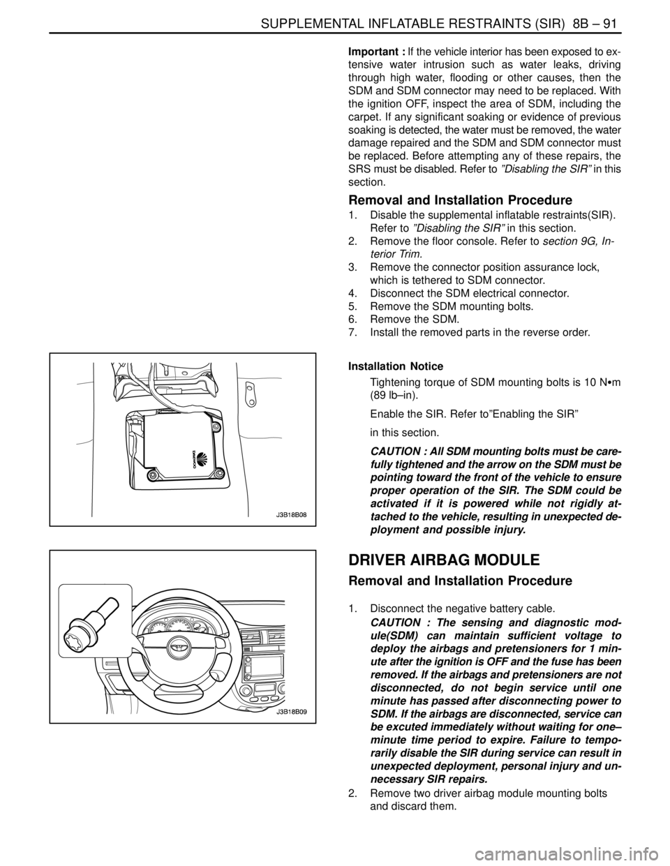
Removal and Installation Procedure
1. Disable the supplemental inflatable restraints(SIR).
Refer to ”Disabling the SIR” in this section.
2. Remove the floor console. Refer to section 9G, In-
terior Trim.
3. Remove the connector position assurance lock,
which is tethered to SDM connector.
4. Disconnect the SDM electrical connector.
5. Remove the SDM mounting bolts.
6. Remove the SDM.
7. Install the removed parts in the reverse order.
Installation Notice
Tightening torque of SDM mounting bolts is 10 NSm
(89 lb–in).
Enable the SIR. Refer to”Enabling the SIR”
in this section.
CAUTION : All SDM mounting bolts must be care-
fully tightened and the arrow on the SDM must be
pointing toward the front of the vehicle to ensure
proper operation of the SIR. The SDM could be
activated if it is powered while not rigidly at-
tached to the vehicle, resulting in unexpected de-
ployment and possible injury.
0
DRIVER AIRBAG MODULE
Removal and Installation Procedure
1. Disconnect the negative battery cable.
CAUTION : The sensing and diagnostic mod-
ule(SDM) can maintain sufficient voltage to
deploy the airbags and pretensioners for 1 min-
ute after the ignition is OFF and the fuse has been
removed. If the airbags and pretensioners are not
disconnected, do not begin service until one
minute has passed after disconnecting power to
SDM. If the airbags are disconnected, service can
be excuted immediately without waiting for one–
minute time period to expire. Failure to tempo-
rarily disable the SIR during service can result in
unexpected deployment, personal injury and un-
necessary SIR repairs.
2. Remove two driver airbag module mounting bolts
and discard them.
Page 2196 of 2643

8B – 92ISUPPLEMENTAL INFLATABLE RESTRAINTS (SIR)
DAEWOO V–121 BL4
3. Remove the connector from the driver airbag mod-
ule.
4. Remove the driver airbag module.
CAUTION : When handling an airbag module, al-
ways keep the top the unit facing upward. This
leaves room for the airbag to expand if the mod-
ule unexpectedly deploys. Without room for ex-
pansion, a module suddenly propelled toward a
person or object can cause injury or vehicle dam-
age.
5. Installation should follow the removal procedure in
the reverse order.
Installation Notice
Tightening torque of the driver airbag module mount-
ing bolt is 8 NSm (71 lb–in).
CLOCK SPRING
Removal and Installation Procedure
CAUTION : The sensing and diagnostic mod-
ule(SDM) can maintain sufficient voltage to
deploy the airbags and pretensioners for 1 min-
ute after the ignition is OFF and the fuse has been
removed. If the airbags and pretensioners are not
disconnected, do not begin service until one
minute has passed after disconnecting power to
SDM. If the airbags are disconnected, service can
be excuted immediately without waiting for one–
minute time period to expire. Failure to tempo-
rarily disable the SIR during service can result in
unexpected deployment, personal injury and un-
necessary SIR repairs.
1. Disconnect the negative battery cable.
2. Remove the driver airbag module. Refer to ”Driver
airbag module” in this section.
3. Remove the steering wheel. Refer to Section 6E,
Steering Wheel and Column.
4. Remove the screws from the upper and lower
steering column covers. And remove the covers.
Page 2197 of 2643
SUPPLEMENTAL INFLATABLE RESTRAINTS (SIR) 8B – 93
DAEWOO V–121 BL4
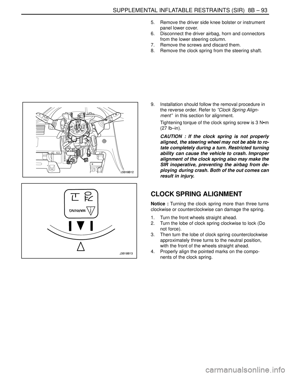
5. Remove the driver side knee bolster or instrument
panel lower cover.
6. Disconnect the driver airbag, horn and connectors
from the lower steering column.
7. Remove the screws and discard them.
8. Remove the clock spring from the steering shaft.
9. Installation should follow the removal procedure in
the reverse order. Refer to ”Clock Spring Align-
ment” in this section for alignment.
Tightening torque of the clock spring screw is 3 NSm
(27 lb–in).
CAUTION : If the clock spring is not properly
aligned, the steering wheel may not be able to ro-
tate completely during a turn. Restricted turning
ability can cause the vehicle to crash. Improper
alignment of the clock spring also may make the
SIR inoperative, preventing the airbag from de-
ploying during crash. Both of the out comes can
result in injury.
CLOCK SPRING ALIGNMENT
Notice : Turning the clock spring more than three turns
clockwise or counterclockwise can damage the spring.
1. Turn the front wheels straight ahead.
2. Turn the lobe of clock spring clockwise to lock (Do
not force).
3. Then turn the lobe of clock spring counterclockwise
approximately three turns to the neutral position,
with the front of the wheels straight ahead.
4. Properly align the pointed marks on the compo-
nents of the clock spring.
Page 2198 of 2643
8B – 94ISUPPLEMENTAL INFLATABLE RESTRAINTS (SIR)
DAEWOO V–121 BL4
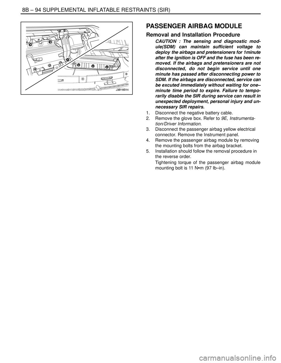
PASSENGER AIRBAG MODULE
Removal and Installation Procedure
CAUTION : The sensing and diagnostic mod-
ule(SDM) can maintain sufficient voltage to
deploy the airbags and pretensioners for 1minute
after the ignition is OFF and the fuse has been re-
moved. If the airbags and pretensioners are not
disconnected, do not begin service until one
minute has passed after disconnecting power to
SDM. If the airbags are disconnected, service can
be excuted immediately without waiting for one–
minute time period to expire. Failure to tempo-
rarily disable the SIR during service can result in
unexpected deployment, personal injury and un-
necessary SIR repairs.
1. Disconnect the negative battery cable.
2. Remove the glove box. Refer to 9E, Instrumenta-
tion/Driver Information.
3. Disconnect the passenger airbag yellow electrical
connector. Remove the Instrument panel.
4. Remove the passenger airbag module by removing
the mounting bolts from the airbag bracket.
5. Installation should follow the removal procedure in
the reverse order.
Tightening torque of the passenger airbag module
mounting bolt is 11 NSm (97 lb–in).
Page 2200 of 2643

8B – 96ISUPPLEMENTAL INFLATABLE RESTRAINTS (SIR)
DAEWOO V–121 BL4
Deployment Procedure
CAUTION : The sensing and diagnostic mod-
ule(SDM) can maintain sufficient voltage to
deploy the airbags and pretensioners for 1 min-
ute after the ignition is OFF and the fuse has been
removed. If the airbags and pretensioners are not
disconnected, do not begin service until one
minute has passed after disconnecting power to
SDM. If the airbags are disconnected, service can
be executed immediately without waiting for
one–minute time period to expire. Failure to tem-
porarily disable the SIR during service can result
in unexpected deployment, personal injury and
unnecessary SIR repairs.
1. Disconnect both battery cables and place the bat-
tery at least 10 meters (33 feet) from the vehicle.
2. Remove the driver side knee bolster or instrument
panel lower cover from the steering column. Refer
to Section 9G, Interior Trim.
3. At the lower steering column, cut the two wires
leading from the supplemental inflatable re-
straints(SIR) harness to the clock spring.
4. Strip 13mm(0.5 inch) of the insulation from the end
of the wires leading to the clock spring.
5. Use two additional wires, each at least 10 me-
ters(33 feet) long, to reach from the deployment
battery to the inflator module.
6. Strip 13mm(0.5 inch) of the insulation from the end
of these two additional wires.
7. Twist the two wires together at one end.
8. Place the twisted ends of the two wires near the
deployment battery. Do not connect the wires to the
battery at this time.
9. Using the free ends of the 10 meters(33 feet) wires
leading to the clock spring, make two splices, one
at each wires from the airbag modules.
10. Wrap the wires with insulation tape.
11. Now that the free ends of the 10 meters(33 feet)
wires are spliced to the airbag module wires, and
the ends that are twisted together are near the de-
ployment battery. Clear the area.
12. Untwist the wires that near the deployment battery.
13. Touch one wire to the positive battery terminal and
touch the other wire to the negative battery termi-
nal. The airbag will deploy.
14. Repeat this procedure for the passenger airbag,
side airbags and pretensioners.
15. Using proper precautions, dispose of the deployed
airbags/pretensioners. Refer to ”Deployed Airbag
Module Disposal Procedure” in this section.
Page 2204 of 2643
8B – 100ISUPPLEMENTAL INFLATABLE RESTRAINTS (SIR)
DAEWOO V–121 BL4
GENERAL DESCRIPTION
AND SYSTEM OPERATION
SUPPLEMENTAL INFLATABLE
RESTRAINTS(SIR)
The supplemental inflatable restraints(SIR) is a safety de-
vice used in conjunction with the seat belt. The air bag
does not replace the fuction of the seatbelt. The driver and
the passengers must always fasten their seat belts and
adjust them for a proper fit.
The SIR is designed to protect the driver and the front seat
passenger in the event of a significant frontal impact to the
vehicle. The airbags deploy if the force is applied from a
direction within 30 degrees of the vehicle’s center line.
The SIR system consists of a
S Driver airbag module
S Driver side airbag module
S Passenger airbag module
S Passenger side airbag module
S Driver’s and front passenger’s seat belt pretension-
ers(and load limiter for some model).
S Sensing and diagnostic module(SDM)
S Clock spring.
S Wire harness and connectors.
S AIRBAG indicator on the instrument cluster.
S Side airbag sensor
AIRBAG MODULES
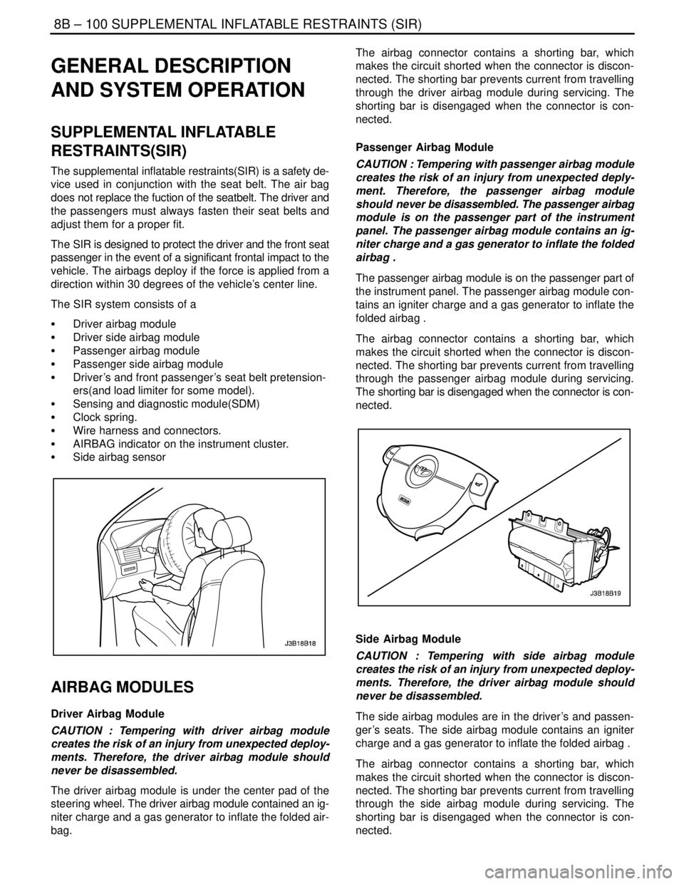
Driver Airbag Module
CAUTION : Tempering with driver airbag module
creates the risk of an injury from unexpected deploy-
ments. Therefore, the driver airbag module should
never be disassembled.
The driver airbag module is under the center pad of the
steering wheel. The driver airbag module contained an ig-
niter charge and a gas generator to inflate the folded air-
bag.The airbag connector contains a shorting bar, which
makes the circuit shorted when the connector is discon-
nected. The shorting bar prevents current from travelling
through the driver airbag module during servicing. The
shorting bar is disengaged when the connector is con-
nected.
Passenger Airbag Module
CAUTION : Tempering with passenger airbag module
creates the risk of an injury from unexpected deply-
ment. Therefore, the passenger airbag module
should never be disassembled. The passenger airbag
module is on the passenger part of the instrument
panel. The passenger airbag module contains an ig-
niter charge and a gas generator to inflate the folded
airbag .
The passenger airbag module is on the passenger part of
the instrument panel. The passenger airbag module con-
tains an igniter charge and a gas generator to inflate the
folded airbag .
The airbag connector contains a shorting bar, which
makes the circuit shorted when the connector is discon-
nected. The shorting bar prevents current from travelling
through the passenger airbag module during servicing.
The shorting bar is disengaged when the connector is con-
nected.
Side Airbag Module
CAUTION : Tempering with side airbag module
creates the risk of an injury from unexpected deploy-
ments. Therefore, the driver airbag module should
never be disassembled.
The side airbag modules are in the driver’s and passen-
ger’s seats. The side airbag module contains an igniter
charge and a gas generator to inflate the folded airbag .
The airbag connector contains a shorting bar, which
makes the circuit shorted when the connector is discon-
nected. The shorting bar prevents current from travelling
through the side airbag module during servicing. The
shorting bar is disengaged when the connector is con-
nected.
Page 2205 of 2643
SUPPLEMENTAL INFLATABLE RESTRAINTS (SIR) 8B – 101
DAEWOO V–121 BL4
FRONT SEAT BELT
PRETENSIONERS
CAUTION : Tempering with seat belt pretensioner
creates the risk of an injury from unexpected deploy-
ment. Therefore, the driver airbag module should
never be disassembled.
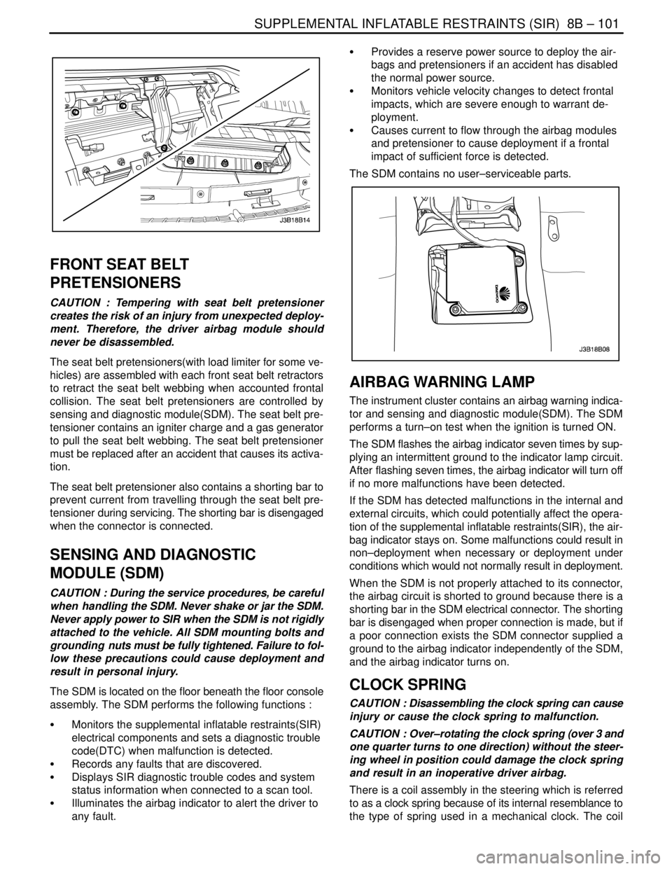
The seat belt pretensioners(with load limiter for some ve-
hicles) are assembled with each front seat belt retractors
to retract the seat belt webbing when accounted frontal
collision. The seat belt pretensioners are controlled by
sensing and diagnostic module(SDM). The seat belt pre-
tensioner contains an igniter charge and a gas generator
to pull the seat belt webbing. The seat belt pretensioner
must be replaced after an accident that causes its activa-
tion.
The seat belt pretensioner also contains a shorting bar to
prevent current from travelling through the seat belt pre-
tensioner during servicing. The shorting bar is disengaged
when the connector is connected.
SENSING AND DIAGNOSTIC
MODULE (SDM)
CAUTION : During the service procedures, be careful
when handling the SDM. Never shake or jar the SDM.
Never apply power to SIR when the SDM is not rigidly
attached to the vehicle. All SDM mounting bolts and
grounding nuts must be fully tightened. Failure to fol-
low these precautions could cause deployment and
result in personal injury.
The SDM is located on the floor beneath the floor console
assembly. The SDM performs the following functions :
S Monitors the supplemental inflatable restraints(SIR)
electrical components and sets a diagnostic trouble
code(DTC) when malfunction is detected.
S Records any faults that are discovered.
S Displays SIR diagnostic trouble codes and system
status information when connected to a scan tool.
S Illuminates the airbag indicator to alert the driver to
any fault.S Provides a reserve power source to deploy the air-
bags and pretensioners if an accident has disabled
the normal power source.
S Monitors vehicle velocity changes to detect frontal
impacts, which are severe enough to warrant de-
ployment.
S Causes current to flow through the airbag modules
and pretensioner to cause deployment if a frontal
impact of sufficient force is detected.
The SDM contains no user–serviceable parts.
AIRBAG WARNING LAMP
The instrument cluster contains an airbag warning indica-
tor and sensing and diagnostic module(SDM). The SDM
performs a turn–on test when the ignition is turned ON.
The SDM flashes the airbag indicator seven times by sup-
plying an intermittent ground to the indicator lamp circuit.
After flashing seven times, the airbag indicator will turn off
if no more malfunctions have been detected.
If the SDM has detected malfunctions in the internal and
external circuits, which could potentially affect the opera-
tion of the supplemental inflatable restraints(SIR), the air-
bag indicator stays on. Some malfunctions could result in
non–deployment when necessary or deployment under
conditions which would not normally result in deployment.
When the SDM is not properly attached to its connector,
the airbag circuit is shorted to ground because there is a
shorting bar in the SDM electrical connector. The shorting
bar is disengaged when proper connection is made, but if
a poor connection exists the SDM connector supplied a
ground to the airbag indicator independently of the SDM,
and the airbag indicator turns on.
CLOCK SPRING
CAUTION : Disassembling the clock spring can cause
injury or cause the clock spring to malfunction.
CAUTION : Over–rotating the clock spring (over 3 and
one quarter turns to one direction) without the steer-
ing wheel in position could damage the clock spring
and result in an inoperative driver airbag.
There is a coil assembly in the steering which is referred
to as a clock spring because of its internal resemblance to
the type of spring used in a mechanical clock. The coil