2004 DAEWOO LACETTI Mirrors
[x] Cancel search: MirrorsPage 5 of 2643

v
TABLE OF CONTENTS
Section 0B General Information
Section 1 Engine
Section 1A General Engine Information
Section 1C1 1.4L/1.6L DOHC Engine Mechanical
Section 1C2 1.8L DOHC Engine Mechanical
Section 1D Engine Cooling
Section 1E Engine Electrical
Section 1F Engine Controls
Section 1G Engine Exhaust
Section 2 Suspension
Section 2A Suspension Diagnosis
Section 2B Wheel Alignment
Section 2C Front Suspension
Section 2D Rear Suspension
Section 2E Tires and Wheels
Section 3 Driveline/Axle
Section 3A Automatic Transaxle Drive Axle
Section 3B Manual Transaxle Drive Axle
Section 4 Brakes
Section 4A Hydraulic Brakes
Section 4B Master Cylinder
Section 4C Power Booster
Section 4D Front Disc Brakes
Section 4E1 Rear Disc Brakes
Section 4E2 Rear Drum Brakes
Section 4F Antilock Brake System
Section 4G Parking Brake
Section 5 Transmission/Transaxle
Section 5A1 ZF 4HP16 Automatic Transaxle
Section 5A2 AISIN Automatic Transaxle
Section 5B Five-Speed Manual Transaxle
Section 5C Clutch
Section 6 Steering
Section 6A Power Steering System
Section 6B Power Steering PumpSection 6C Power Steering Gear
Section 6E Steering Wheel and Column
Section 7 Heating, Ventilation, and Air
Conditioning (HVAC)
Section 7A Heating and Ventilation System
Section 7B Manual Control Heating, Ventilation,
and Air Conditioning System
Section 7D Automatic Temperature Control HVAC
Section 8 Restraints
Section 8A Seat Belts
Section 8B Supplemental Inflatable Restraints
(SIR)
Section 9 Body and Accessories
Section 9A Body Wiring System
Section 9B Lighting Systems
Section 9C Horns
Section 9D Wipers/Washer Systems
Section 9E Instrumentation/Driver Information
Section 9F Audio Systems
Section 9G Interior Trim
Section 9H Seats
Section 9I Waterleaks
Section 9J Windnoise
Section 9K Squeaks and Rattles
Section 9L Glass and Mirrors
Section 9M Exterior Trim
Section 9N Frame and Underbody
Section 9O Bumpers and Fascias
Section 9P Doors
Section 9Q Roof
Section 9R Body Front End
Section 9S Body Rear End
Section 9T1 Remote Keyless Entry and Anti–Theft
System
Section 9T2 Immobilizer Anti–Theft System
Page 2095 of 2643

7D – 40IAUTOMATIC TEMPERATURE CONTROL HEATING, VENTILATION, AND AIR CONDITIONING SYSTEM
DAEWOO V–121 BL4
GENERAL DESCRIPTION
AND SYSTEM OPERATION
GENERAL INFORMATION
THE V5 SYSTEM
Refer to Section 7B, Manual Control Heating, Ventilation,
and Air Conditioning System,for general information de-
tails for the following:
S System Components – Functional.
S The V5 A/C System.
S V5 Compressor – Description of Operation.
S V5 Compressor – General Description.
SYSTEM COMPONENTS–CONTROL
Controller
The operation of the A/C system is controlled by the
switches on the control head. This console–mounted
heating and ventilation system contains the following
knobs and display:
Temperature Control Push Knobs
1. Raise the temperature of the air entering the ve-
hicle by pressing the top switch, with the red arrow
pointing upward.
2. Lower the temperature by pressing the bottom
switch, with the blue arrow pointing downward.
3. Actuate the air mix door by an electric motor.
4. Vary the mix of the air passing through the heater
core with the air bypassing the core.
Each press of a switch changes the set temperature by in-
crements of 0.5°C (1°F). This is shown in the temperature
window on the function display.
The Function Display
This is an LCD display indicating the status of the control
settings selected. Starting from the left end of the display,
the sections are as follows:
1. Temperature setting – Indicates the temperature set
with the temperature control knob.
2. Auto status – Indicates whether the system is oper-
ating in the full auto mode or the manual mode.
3. Defroster icon – Indicates manual selection of full
defrost mode.
4. Mode – Indicated by icon, the mode chosen by the
system in auto (or by the operator in manual) is
shown by an illumination arrow indicating the air
path.
5. A/C – A snowflake icon indicating whether the A/C
is ON or OFF.
6. Fan speed – Indicates the fan speed by illuminating
a bar based on the segment at the front, for low
speed, and adding additional segments in order up
to the fifth, for high speed.Eight Additional Push Knobs
1. Full defrost – Causes the mode motors to direct all
air to the windshield and aide window outlets for
maximum defrosting.
2. Air intake – Switches between fresh air intake, the
default, and recirculating air. Airflow arrows on the
display indicate the mode in effect.
3. Full Auto Switch – Maintains the set temperature
automatically. In this mode, the fully automatic tem-
perature control (FATC) system controls the follow-
ing:
S The air mix door motor.
S The mode door motor.
S The blower motor speed.
S The inlet air door motor.
S A/C ON/OFF.
4. OFF Switch – Turns the automatic air conditioning
and fan control off.
5. Mode Switch – Allows manual selection of the air-
flow direction.
S Selection is shown on the function display.
S Each time the mode switch is pressed, the next
function is displayed.
6. A/C Switch – Allows manual selection and control
of the air conditioning function.
7. Fan Control Switch – Allows manual selection
among five fan speeds.
8. Defogger Switch – Turns on the electric defogging
heater in the rear window and the outside rearview
mirrors, if the vehicle is equipped with heated mir-
rors.
Pressure Transducer
Pressure transducer switching incorporates the functions
of the high–pressure and the low–pressure cutout
switches along with the fan cycling switch. The pressure
transducer is located in the high–side liquid refrigerant line
behind the right strut tower, between the right strut tower
and the fire wall. The output from this pressure transducer
goes to the electronic control module (ECM), which con-
trols the compressor function based on the pressure sig-
nal.
Wide–Open Throttle (WOT) Compressor
Cutoff
During full–throttle acceleration, the throttle position sen-
sor (TPS) sends a signal to the ECM, which then controls
the compressor clutch.
High RPM Cutoff
As engine rpm approaches the maximum limit, the ECM
will disengage the compressor clutch until the engine
slows to a lower rpm.
Page 2376 of 2643

9J – 2IWINDNOISE
DAEWOO V–121 BL4
MAINTENANCE AND REPAIR
ON–VEHICLE SERVICE
WINDNOISE REPAIR
Windnoise leak repairs are very similar to waterleak re-
pairs. Refer to Section 9I, Waterleaks. The actual proce-
dure depends on the type of seal being repaired.
Leaks around the door opening weatherstrips do not al-
ways indicate a faulty weatherstrip. A door or window ad-
justment may resolve the condition. Refer to Section 9P,
Doors or Section 9L, Glass and Mirrors.
Page 2380 of 2643

SECTION : 9L
GLASS AND MIRRORS
CAUTION : Disconnect the negative battery cable before removing or installing any electrical unit or when a tool
or equipment could easily come in contact with exposed electrical terminals. Disconnecting this cable will help
prevent personal injury and damage to the vehicle. The ignition must also be in LOCK unless otherwise noted.
TABLE OF CONTENTS
SPECIFICATIONS9L–2 . . . . . . . . . . . . . . . . . . . . . . . . . . .
Fastener Tightening Specifications 9L–2. . . . . . . . . . . .
SPECIAL TOOLS9L–2 . . . . . . . . . . . . . . . . . . . . . . . . . . . .
Special Tools Table 9L–2. . . . . . . . . . . . . . . . . . . . . . . . .
SCHEMATIC AND ROUTING DIAGRAMS9L–3 . . . . . .
Defogger System 9L–3. . . . . . . . . . . . . . . . . . . . . . . . . . .
Electric Control OSRV (Outside Rear View)
Mirror System 9L–4. . . . . . . . . . . . . . . . . . . . . . . . . . . .
DIAGNOSIS9L–5 . . . . . . . . . . . . . . . . . . . . . . . . . . . . . . . . .
Testing Rear Window Defogger Grid Line 9L–5. . . . . .
Outside Rearview Mirror Defoggers 9L–5. . . . . . . . . . .
Electric Control Outside Rearview Mirrors 9L–6. . . . . .
Folding Mirror Unit 9L–8. . . . . . . . . . . . . . . . . . . . . . . . . .
MAINTENANCE AND REPAIR9L–10 . . . . . . . . . . . . . . .
ON–VEHICLE SERVICE 9L–10. . . . . . . . . . . . . . . . . . . . .
Windshield 9L–10. . . . . . . . . . . . . . . . . . . . . . . . . . . . . . . . Rear Window Glass 9L–11. . . . . . . . . . . . . . . . . . . . . . . .
Rear Window Defogger Grid Line Repair 9L–13. . . . . .
Rear Window Defogger Braided Lead Wire
Repair 9L–15. . . . . . . . . . . . . . . . . . . . . . . . . . . . . . . . . .
Front Door Glass 9L–15. . . . . . . . . . . . . . . . . . . . . . . . . .
Rear Door Glass 9L–16. . . . . . . . . . . . . . . . . . . . . . . . . . .
Rear Door Quarter Glass 9L–16. . . . . . . . . . . . . . . . . . .
Inside Rearview Mirror 9L–17. . . . . . . . . . . . . . . . . . . . .
Outside Rearview Mirrors 9L–18. . . . . . . . . . . . . . . . . . .
Folding Mirrors Unit 9L–18. . . . . . . . . . . . . . . . . . . . . . . .
GENERAL DESCRIPTION AND SYSTEM
OPERATION9L–19 . . . . . . . . . . . . . . . . . . . . . . . . . . . . . .
Stationary Glass 9L–19. . . . . . . . . . . . . . . . . . . . . . . . . . .
Electric Control Heated Outside Rearview
Mirror 9L–19. . . . . . . . . . . . . . . . . . . . . . . . . . . . . . . . . .
Inside Rearview Mirror 9L–19. . . . . . . . . . . . . . . . . . . . .
Folding Mirror Unit 9L–19. . . . . . . . . . . . . . . . . . . . . . . . .
Page 2381 of 2643

9L – 2IGLASS AND MIRRORS
DAEWOO V–121 BL4
SPECIFICATIONS
FASTENER TIGHTENING SPECIFICATIONS
ApplicationNSmLb–FtLb–In
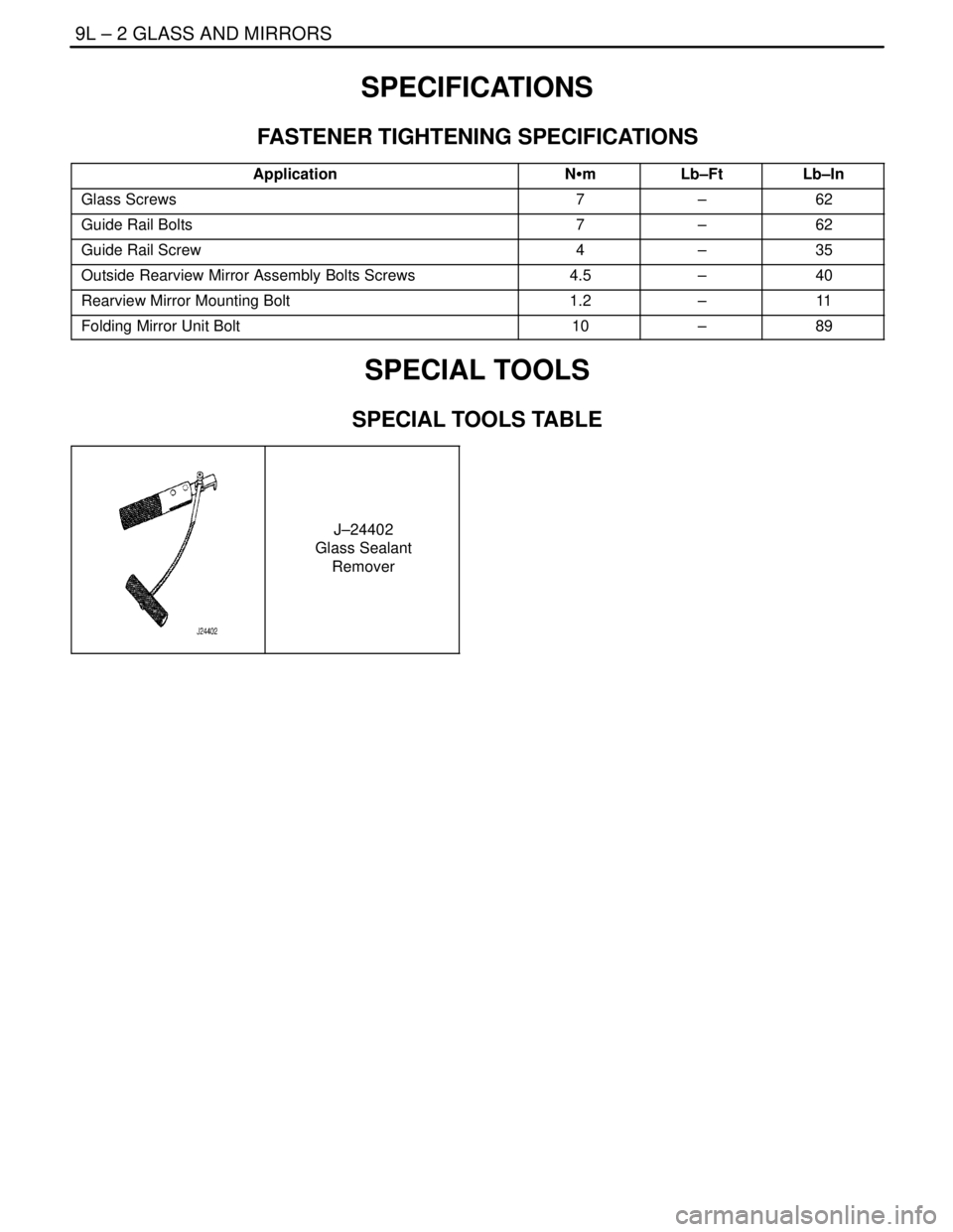
Glass Screws7–62
Guide Rail Bolts7–62
Guide Rail Screw4–35
Outside Rearview Mirror Assembly Bolts Screws4.5–40
Rearview Mirror Mounting Bolt1.2–11
Folding Mirror Unit Bolt10–89
SPECIAL TOOLS
SPECIAL TOOLS TABLE
J–24402
Glass Sealant
Remover
Page 2382 of 2643

GLASS AND MIRRORS 9L – 3
DAEWOO V–121 BL4
SCHEMATIC AND ROUTING DIAGRAMS
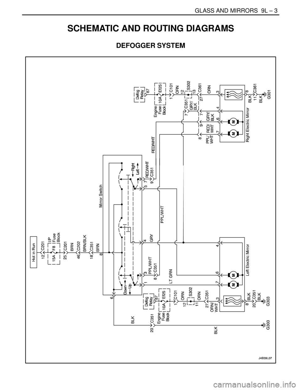
DEFOGGER SYSTEM
Page 2383 of 2643

9L – 4IGLASS AND MIRRORS
DAEWOO V–121 BL4
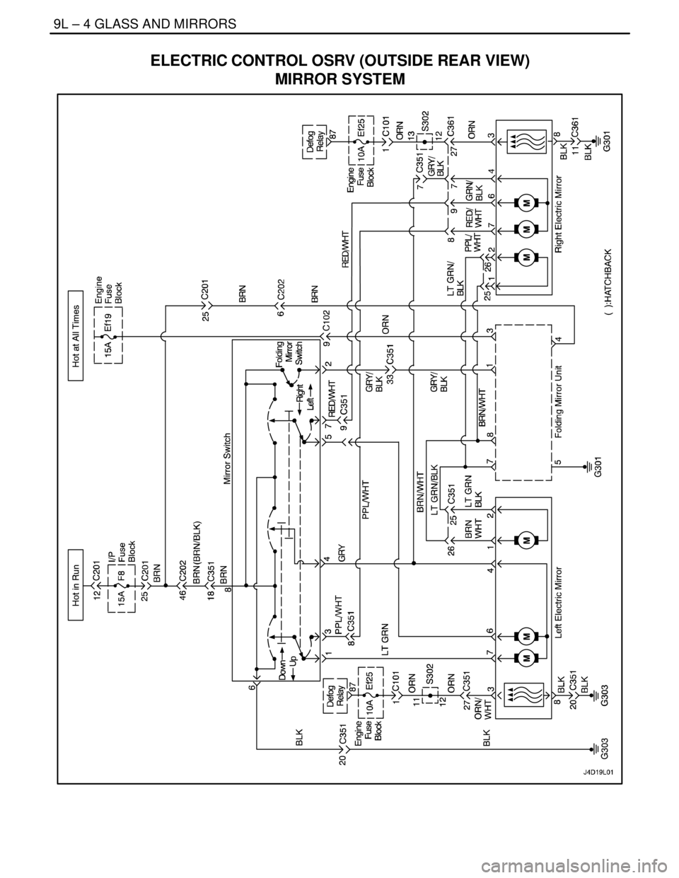
ELECTRIC CONTROL OSRV (OUTSIDE REAR VIEW)
MIRROR SYSTEM
Page 2384 of 2643

GLASS AND MIRRORS 9L – 5
DAEWOO V–121 BL4
DIAGNOSIS
TESTING REAR WINDOW
DEFOGGER GRID LINE
If it has been observed during use that a grid line is inop-
erative, the following procedure can be used to find the
break. If none of the grid lines is operating, a full system
diagnosis should be completed before attempting to repair
the grid lines.
1. Turn the ignition ON.
2. Turn the rear window defogger on.
3. From the inside of the vehicle, connect a voltmeter
to each end of a grid line. The voltmeter will indi-
cate battery voltage if the grid line is open.
Notice : Use care when touching the voltmeter leads to a
grid line. If the leads are roughly applied, the grid line may
be scratched, resulting in an open circuit.4. If a grid line is found to be open, move a voltmeter
lead from one side of the grid line and retest at a
point nearer to the other side of the window. Contin-
ue to retest, each time bringing one of the voltmeter
leads closer to the opposite side of the window
from where it was originally placed. The break in
the grid line is at the point where the voltmeter be-
gins reading 0 volts instead of battery voltage.
5. Use a marking crayon to lightly mark the break
point on the rear window. Mark the glass instead of
marking directly on the grid line, and make the
mark far enough from the grid line so that it can
easily be removed without disturbing the repair.
6. Use a grid line repair kit to fix the break in the grid
line. Refer to ”Rear Window Defogger Grid Line
Repair” in this section.
OUTSIDE REARVIEW MIRROR DEFOGGERS
StepActionValue(s)YesNo
1Check the rear window defogger.
Does the rear window defogger work?–Go to Step 4 Go to Step 2
2Repair the rear window defogger before proceeding
with the outside rearview mirror diagnosis.
Is the repair complete?–Go to Step 3–
3Test the outside rearview mirror defoggers.
Does the repair of the rear window defogger system
also fix the problem with the outside rearview mirror
defoggers?–System OKGo to Step 4
4Check fuse Ef25.
Is fuse Ef25 blown?–Go to Step 5 Go to Step 6
51. Check for a short circuit and repair it, if neces-
sary.
2. Replace the fuse.
Is the repair complete?–System OK–
61. On the side of the vehicle which has the mal-
functioning outside rearview mirror defogger,
remove the black plastic escutcheon from the
trim panel side of the door.
2. Disconnect the outside rearview mirror electri-
cal connector.
3. Turn the ignition ON.
4. Turn on the defogger.
5. Use a voltmeter to backprobe terminal 3 (ORN)
at the outside rearview mirror electrical connec-
tor.
Does the voltmeter indicate the specified value?11–14 v Go to Step 8 Go to Step 7
7Repair the open circuit between fuse Ef25 and the
outside rearview mirror connector.
Is the repair complete?–System OK–