Page 1777 of 2643
AISIN AUTOMATIC TRANSAXLE 5A2 – 187
DAEWOO V–121 BL4
15. Using a small screwdriver, remove the O–ring from
the forward clutch drum.
16. Using a small screwdriver, remove the O–ring from
the intermediate shaft sub–assembly.
Inspection Procedure
1. Check to see if the sliding surface of the disc, plate
flange are worn or burnt. If necessary, replace
them.
S If the lining of the disc is peeling off or discol-
ored, or even if a part of the printed number is
defaced, replace all discs.
S Before assembling new discs, soak them in ATF
for at least 15 minutes.
2. Using vernier calipers, measure the free length of
the spring together with the spring seat.
S Standard free length: 24.04 mm (0.9465 in.)
Page 1779 of 2643
AISIN AUTOMATIC TRANSAXLE 5A2 – 189
DAEWOO V–121 BL4
5. Install the forward clutch return spring and clutch
balancer.
Notice : Be careful not to damage the lip seal of forward
clutch return spring.
6. Place brake/clutch spring compressor DW240–020
and forward clutch adapter DW240–030 on the
clutch balancer and compress the piston return
spring.
7. Using a snap ring expander, install the snap ring.
Notice : Stop the press when the clutch balancer is low-
ered to the place 1–2 mm (0.039–0.078 in.) from the snap
ring groove, preventing the clutch balancer from being de-
formed.
Notice : Do not expand the snap ring excessively.
8. Install the 3 plates, 3 discs and flange.
S Install in order: P � D � P � D � P � D – F
(P = Plate, D = Disc, F = Flange)
9. Using a screwdriver, install the snap ring.
10. Check that the end gap of the snap ring is not
aligned with one of the cutouts.
Page 1780 of 2643

5A2 – 190IAISIN AUTOMATIC TRANSAXLE
DAEWOO V–121 BL4
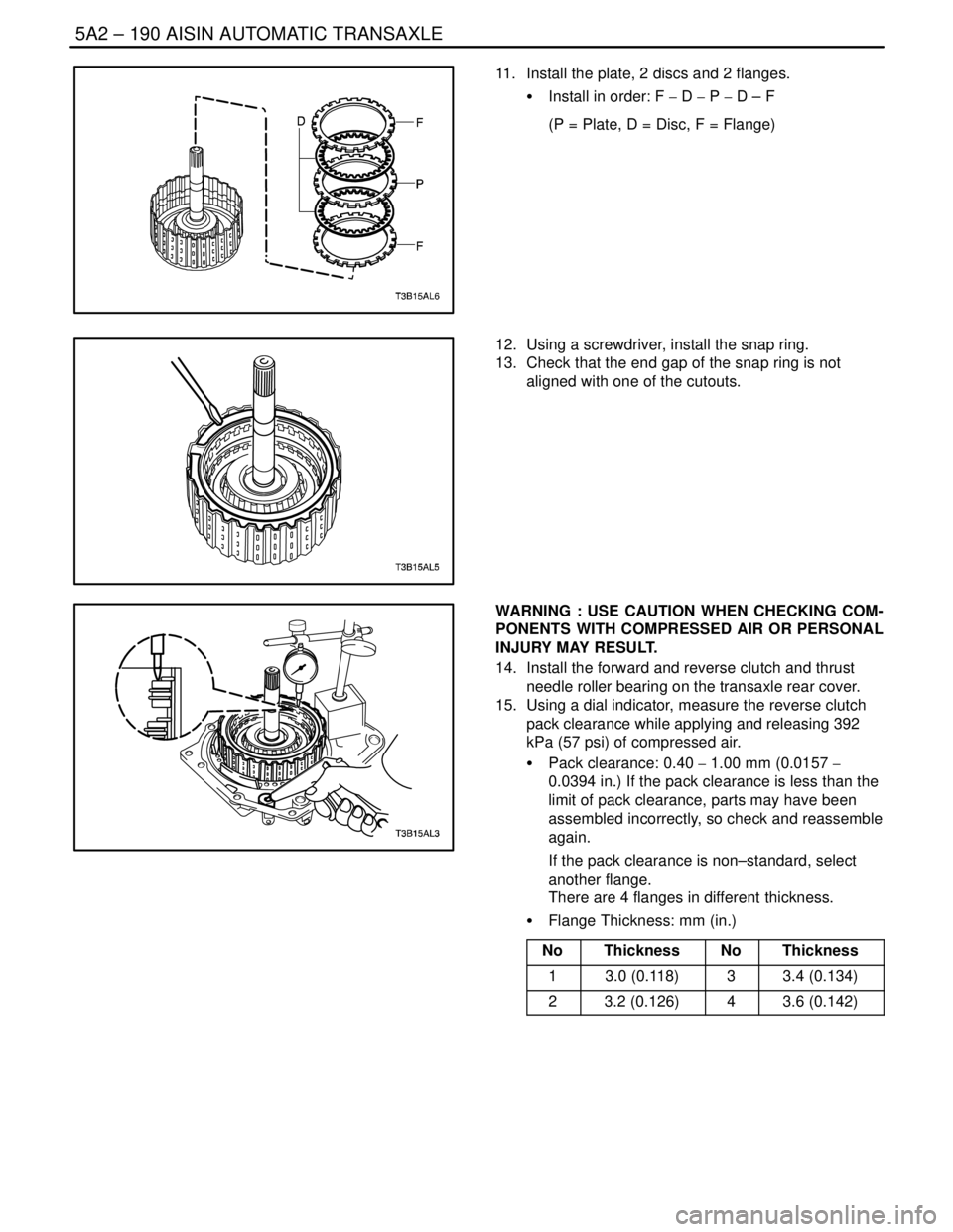
11. Install the plate, 2 discs and 2 flanges.
S Install in order: F � D � P � D – F
(P = Plate, D = Disc, F = Flange)
12. Using a screwdriver, install the snap ring.
13. Check that the end gap of the snap ring is not
aligned with one of the cutouts.
WARNING : USE CAUTION WHEN CHECKING COM-
PONENTS WITH COMPRESSED AIR OR PERSONAL
INJURY MAY RESULT.
14. Install the forward and reverse clutch and thrust
needle roller bearing on the transaxle rear cover.
15. Using a dial indicator, measure the reverse clutch
pack clearance while applying and releasing 392
kPa (57 psi) of compressed air.
S Pack clearance: 0.40 � 1.00 mm (0.0157 �
0.0394 in.) If the pack clearance is less than the
limit of pack clearance, parts may have been
assembled incorrectly, so check and reassemble
again.
If the pack clearance is non–standard, select
another flange.
There are 4 flanges in different thickness.
S Flange Thickness: mm (in.)
No
ThicknessNoThickness
13.0 (0.118)33.4 (0.134)
23.2 (0.126)43.6 (0.142)
Page 1801 of 2643
AISIN AUTOMATIC TRANSAXLE 5A2 – 211
DAEWOO V–121 BL4
9. Using a driver, remove the oil seal from the trans-
axle housing.
Notice : Be careful not to damage the transaxle housing
when removing the oil seal using a driver.
10. Using a suitable puller, remove the side bearing
outer race of transaxle housing.
11. Using a driver, remove the oil seal of transaxle
case.
Notice : Be careful not to damage the transaxle case
when removing the oil seal using a driver.
12. Using transaxle case side bearing outer race adapt-
er DW240–150 and adapter handle DW240–170,
remove the transaxle case side bearing outer race
and shim.
Page 1808 of 2643

5A2 – 218IAISIN AUTOMATIC TRANSAXLE
DAEWOO V–121 BL4
GENERAL DESCRIPTION
AND SYSTEM OPERATION
TRANSAXLE DESCRIPTION
The new automatic transmission is an electronically con-
trolled 4–speed automatic transmission with Lock–up
mechanism.
The transmission is mainly composed of the torque con-
verter with lock up clutch, newly developed 4–speed plan-
etary gear unit, the hydraulic control system and the elec-
tric control system.
ELECTRONICAL COMPONENTS
Transmission Control Module (TCM)
The TCM primarily controls shift points and lockup en-
gagement. It is located on the driver side under the instru-
ment panel.
The transmission is controlled by an electronic shift sys-
tem. The Transmission Control Module (TCM) processes
input signals. From the information received, the TCM
controls the transmission hydraulic system.
The electronic shift system consists of the following :
S Transmission control module (TCM)
S Shift solenoids (SS1 and SS2)
S Pressure control solenoid (PCS)
S Lockup solenoid
S Input shaft speed (ISS) sensor
S Output shaft speed (OSS) sensor
S Transmission Fluid Temperature (TFT) sensor
S Transmission Range (TR) Switch
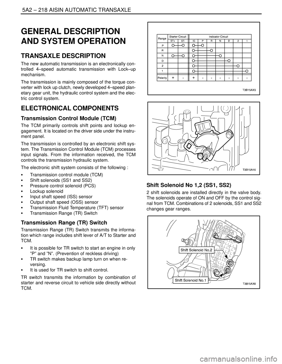
Transmission Range (TR) Switch
Transmission Range (TR) Switch transmits the informa-
tion which range includes shift lever of A/T to Starter and
TCM.
S It is possible for TR switch to start an engine in only
”P” and ”N”. (Prevention of reckless driving)
S TR switch makes backup lamp turn on when re-
versing.
S It is used for TR switch to shift control.
TR switch transmits the information by combination of
starter and reverse circuit to vehicle side directly without
TCM.
Shift Solenoid No 1,2 (SS1, SS2)
2 shift solenoids are installed directly in the valve body.
The solenoids operate of ON and OFF by the control sig-
nal from TCM. Combinations of 2 solenoids, SS1 and SS2
changes gear ranges.
Page 1889 of 2643
5C – 2ICLUTCH
DAEWOO V–121 BL4
SPECIAL TOOLS
SPECIAL TOOLS TABLE
J–42474
Clutch Arbor
DIAGNOSIS
CLUTCH OPERATION
Intermittent Clutch Operation
ChecksAction
Check for the driver improperly operating the vehicle.Correct the driver’s operation of the vehicle as necessary.
Check for the improper clutch pedal play.Adjust the clutch pedal play.
Check for the insufficient oil or the leak at oil pressure line.Repair the leak or add the oil.
Check for a warped or worn clutch disc.Replace the clutch disc.
Check for worn splines on the input shaft.Repair or Replace the splines on the input shaft.
Check for a weak diaphragm spring.Replace the pressure plate.
Clutch Slipping
ChecksAction
Check for a stuck concentric slave cylinder.Replace the concentric slave cylinder.
Check for improper return of clutch oil.Perform the air bleeding.
Check for a worn clutch disc or oil contamination.Replace the clutch disc.
Check for a warped pressure plate.Replace the pressure plate.
Page 1926 of 2643

POWER STEERING GEAR 6C – 9
DAEWOO V–121 BL4
StepNo Yes Value(s) Action
23Repair the open, short to ground, short to B+, or poor
terminal contact between terminal 14 of the SSPS
control module connector and terminal 2 of the
steering wheel rotation sensor connector.
Is the repair complete?–System OK–
241. Turn the ignition OFF.
2. Connect the SSPS control module.
3. Connect the steering wheel rotation sensor.
4. Turn the ignition ON.
5. Backprobe with a voltmeter from terminal 5 on
the control module connector to the ground.
6. Rotate the steering wheel quickly in both direc-
tions.
Does the voltage show an increase and decrease
from the specified value?� 3 VGo to Step 25Go to Step 26
25Replace the SSPS control module.
Is the repair complete?–System OK–
26Replace the steering wheel rotation sensor.
Is the repair complete?–System OK–
SPEED SENSITIVE POWER STEERING SYSTEM
OPERATING WITH DECREASED ASSIST AT ALL TIMES
StepActionValue(s)YesNo
1Check the speedometer.
Is speedometer inoperative?–Go to
Section5,
TransaxleGo to Step 2
2Disconnect the EVO solenoid actuator at the power
steering pump.
Is the symptom still present?–Go to
Section 6A,
Power Steering
SystemGo to Step 3
3Replace the speed sensitive poser steering (SSPS)
control module.
Is repair complete?–System OK–
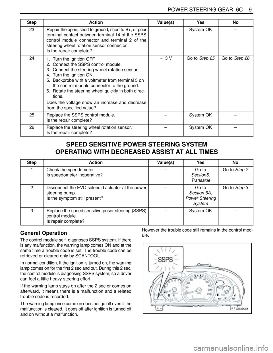
General Operation
The control module self–diagnoses SSPS system. If there
is any malfunction, the warning lamp comes ON and at the
same time a trouble code is set. The trouble code can be
retrieved or cleared only by SCANTOOL.
In normal condition, If the ignition is turned on, the warning
lamp comes on for the first 2 sec and out. During this 2 sec,
the control module is diagnosing SSPS system, so a driver
can feel a little heavy steering effort.
If the warning lamp stays on after the 2 sec or comes on
afterward, it means there is a malfunction and a related
trouble code is recorded.
The warning lamp once come on does not go off even if the
malfunction is cleared. It goes off after ignition is turned off
and on without a malfunction.However the trouble code still remains in the control mod-
ule.
Page 1940 of 2643
POWER STEERING GEAR 6C – 23
DAEWOO V–121 BL4
8. Push back the plastic retainer protecting the con-
nection between the inner tie rod and the power
steering gear rack.
9. Counterhold the pinion–side inner tie rod and re-
move the cylinder–side inner tie rod.
10. Place a rag over the rack, counterhold the rack as-
sembly on the teeth with a wrench, and remove the
pinion–side inner tie rod.
Important : The retaining ring can be released by insert-
ing a small screwdriver through the hole in the side of the
housing.
11. Remove the bulkhead inner cylinder retaining ring
the bulkhead inner cylinder and the rack.