2004 DAEWOO LACETTI driver
[x] Cancel search: driverPage 1950 of 2643

POWER STEERING GEAR 6C – 33
DAEWOO V–121 BL4
GENERAL DESCRIPTION
AND SYSTEM OPERATION
POWER RACK AND PINION
The power rack and pinion steering system has a rotary
control valve that directs hydraulic fluid coming from the
hydraulic pump to one side or the other side of the rack pis-
ton. The integral rack piston is attached to the rack. The
rack piston converts hydraulic pressure to a linear force
that moves the rack left or right. That force is then trans-
mitted through the tie rods to the steering knuckles, which
turn the wheels.
If power rack and pinion steering is not available, manual
rack and pinion control is used; however, with this system,
more steering effort is required. The movement of the
steering wheel is transferred to the pinion. The rotary
movement of the pinion is then transferred through the pin-
ion threads, which mesh with teeth on the rack, thereby
causing the rack to move in a linear direction.
A vane–type of hydraulic pump provides hydraulic pres-
sure for both steering systems.
SPEED SENSITIVE POWER
STEERING SYSTEM
The speed sensitive power steering (SSPS) system varies
the driver effort required to steer as the vehicle speed
changes. At low speeds, the system provides maximum
power assist for easy turning and parking maneuvers. At
higher speeds, the steering power is reduced to provide
the driver with firmer steering and directional stability. The
SSPS system accomplishes this by reducing the amount
of power steering fluid flow from the power steering pump
to the power steering gear as the vehicle speed increases.
When the vehicle is stationary, the SSPS system provides
maximum fluid flow to the steering gear. As the vehicle
speed increases, the fluid flow to the steering gear is de-
creased.
Control Module
The SSPS control module processes the vehicle speed in-
formation from the engine control module (ECM) and uses
the steering wheel rotation sensor to provide a control sig-
nal to the electronic variable orifice (EVO) actuator located
on the power steering pump.
Electronic Variable Orifice (EVO) Actuator
The electronic variable orifice (EVO) actuator is located on
the power steering pump and contains a solenoid– oper-
ated pintle valve. Fluid leaving the pump passes through
an orifice in the actuator tip. When the EVO actuator is
powered by the SSPS control module, the pintle moves
into the orifice and reduces the power steering fluid flow.As the vehicle speed increases, current from the SSPS
control module increases, and the pintle blocks more and
more of the orifice.
Steering Wheel Rotation Sensor
The steering wheel rotation sensor is located at the end of
the steering column housing and is used to send a signal
to the controller when abrupt or evasive steering maneu-
vers are needed.
Power Steering Pressure Hose
SSPS vehicles have a specific pressure hose assembly
which includes an in–line check valve in the rack and pin-
ion assembly. This reduces the amount of steering wheel
”kick” when driving over irregular road surfaces while oper-
ating at speeds with reduced flow rate and pressure.
Power Rack and Pinion
Except for differences in valve machining, the design of
the SSPS power rack and pinion assembly is the same as
for the a non–SSPS system. The steering wheel move-
ment is transferred to the pinion via the intermediate shaft.
The pinion moves the rack left or right through meshing the
pinion and the rack teeth. The force is then transmitted
through the tie rods and steering knuckle to steer the
wheels.
The power rack and pinion steering system has a rotary
control valve which directs the hydraulic fluid from the
power steering pump to one side or the other side of the
rack piston. The piston is attached to the rack and uses hy-
draulic pressure to move the rack left or right. The rotary
control valve regulates the degree of assist by responding
to the driver’s torque input.
If hydraulic assist is not available, manual control is main-
tained. However, under this condition, more steering effort
is required.
Power Steering Pump
The standard vane–type pump, which provides hydraulic
pressure for the system, incorporates a special discharge
fitting to hold the EVO actuator.
System Operation
System operation originates with input from the vehicle
speed sensor via the engine control module to the SSPS
control module. The SSPS control module sends a signal
to the SSPS actuator to vary the rate of fluid flow output
by the power steering pump.
Circuit Operation
The SSPS system uses inputs from the speed sensor and
steering wheel rotation sensor to the SSPS controller to
determine the desired amount of power steering assist.
The SSPS control module constantly compares the
amount of current flowing through the EVO actuator to the
desired current it has calculated. The EVO actuator has a
pintle that moves in and out of an orifice, regulating power
Page 1951 of 2643
6C – 34IPOWER STEERING GEAR
DAEWOO V–121 BL4
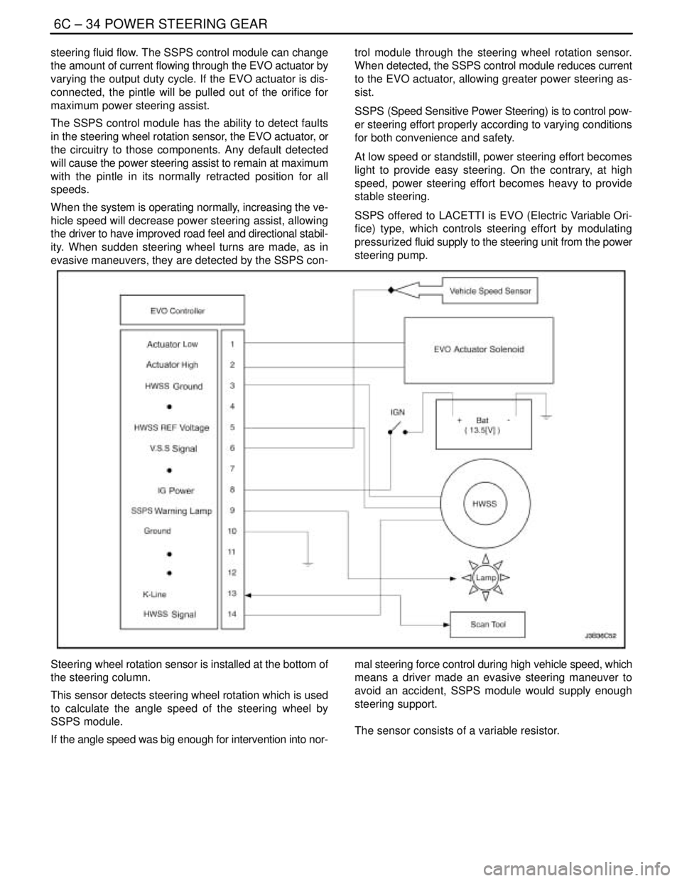
steering fluid flow. The SSPS control module can change
the amount of current flowing through the EVO actuator by
varying the output duty cycle. If the EVO actuator is dis-
connected, the pintle will be pulled out of the orifice for
maximum power steering assist.
The SSPS control module has the ability to detect faults
in the steering wheel rotation sensor, the EVO actuator, or
the circuitry to those components. Any default detected
will cause the power steering assist to remain at maximum
with the pintle in its normally retracted position for all
speeds.
When the system is operating normally, increasing the ve-
hicle speed will decrease power steering assist, allowing
the driver to have improved road feel and directional stabil-
ity. When sudden steering wheel turns are made, as in
evasive maneuvers, they are detected by the SSPS con-trol module through the steering wheel rotation sensor.
When detected, the SSPS control module reduces current
to the EVO actuator, allowing greater power steering as-
sist.
SSPS (Speed Sensitive Power Steering) is to control pow-
er steering effort properly according to varying conditions
for both convenience and safety.
At low speed or standstill, power steering effort becomes
light to provide easy steering. On the contrary, at high
speed, power steering effort becomes heavy to provide
stable steering.
SSPS offered to LACETTI is EVO (Electric Variable Ori-
fice) type, which controls steering effort by modulating
pressurized fluid supply to the steering unit from the power
steering pump.
Steering wheel rotation sensor is installed at the bottom of
the steering column.
This sensor detects steering wheel rotation which is used
to calculate the angle speed of the steering wheel by
SSPS module.
If the angle speed was big enough for intervention into nor-mal steering force control during high vehicle speed, which
means a driver made an evasive steering maneuver to
avoid an accident, SSPS module would supply enough
steering support.
The sensor consists of a variable resistor.
Page 1964 of 2643
6E – 10ISTEERING WHEEL AND COLUMN
DAEWOO V–121 BL4
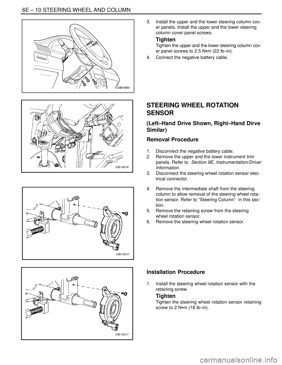
3. Install the upper and the lower steering column cov-
er panels. Install the upper and the lower steering
column cover panel screws.
Tighten
Tighten the upper and the lower steering column cov-
er panel screws to 2.5 NSm (22 lb–in).
4. Connect the negative battery cable.
STEERING WHEEL ROTATION
SENSOR
(Left–Hand Drive Shown, Right–Hand Dirve
Similar)
Removal Procedure
1. Disconnect the negative battery cable.
2. Remove the upper and the lower instrument trim
panels. Refer to Section 9E, Instrumentation/Driver
Information.
3. Disconnect the steering wheel rotation sensor elec-
trical connector.
4. Remove the intermediate shaft from the steering
column to allow removal of the steering wheel rota-
tion sensor. Refer to ”Steering Column” in this sec-
tion.
5. Remove the retaining screw from the steering
wheel rotation sensor.
6. Remove the steering wheel rotation sensor.
Installation Procedure
1. Install the steering wheel rotation sensor with the
retaining screw.
Tighten
Tighten the steering wheel rotation sensor retaining
screw to 2 NSm (18 lb–in).
Page 1965 of 2643
STEERING WHEEL AND COLUMN 6E – 11
DAEWOO V–121 BL4
2. Install the intermediate shaft onto the steering col-
umn. Refer to ”Steering Column” in this section.
3. Connect the steering wheel rotation sensor electri-
cal connector.
4. Install the upper and the lower instrument trim pan-
els. Refer to Section 9E, Instrumentation/Driver
Information.
5. Connect the negative battery cable.
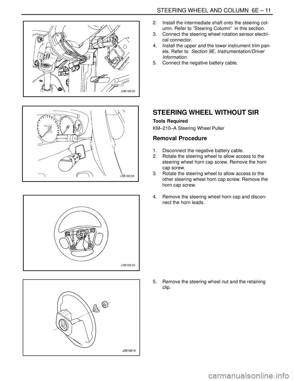
STEERING WHEEL WITHOUT SIR
Tools Required
KM–210–A Steering Wheel Puller
Removal Procedure
1. Disconnect the negative battery cable.
2. Rotate the steering wheel to allow access to the
steering wheel horn cap screw. Remove the horn
cap screw.
3. Rotate the steering wheel to allow access to the
other steering wheel horn cap screw. Remove the
horn cap screw.
4. Remove the steering wheel horn cap and discon-
nect the horn leads.
5. Remove the steering wheel nut and the retaining
clip.
Page 1969 of 2643
STEERING WHEEL AND COLUMN 6E – 15
DAEWOO V–121 BL4
STEERING COLUMN
(Left–Hand Drive Shown, Right–Hand Dirve
Similar)
Important : Remove the steering column only if the follow-
ing conditions exist:
S The steering column requires replacement.
S The steering and the ignition lock housing require
replacement.
S Another operation requires the removal of the
steering column.
Notice : The steering column is extremely susceptible to
damage after it has been removed from the vehicle. Drop-
ping the column assembly on its end or hammering the
end of the steering shaft can collapse the steering shaft or
loosen the plastic injections which maintain column rigid-
ity. Leaning on the column can cause it to bend or deform.
Any of the above damage can impair the column’s collaps-
ible design. If it is necessary to remove the steering wheel,
use only the specified steering wheel puller.
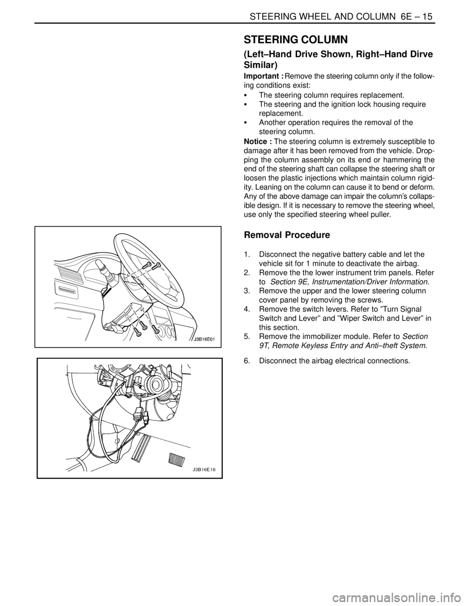
Removal Procedure
1. Disconnect the negative battery cable and let the
vehicle sit for 1 minute to deactivate the airbag.
2. Remove the the lower instrument trim panels. Refer
to Section 9E, Instrumentation/Driver Information.
3. Remove the upper and the lower steering column
cover panel by removing the screws.
4. Remove the switch levers. Refer to ”Turn Signal
Switch and Lever” and ”Wiper Switch and Lever” in
this section.
5. Remove the immobilizer module. Refer to Section
9T, Remote Keyless Entry and Anti–theft System.
6. Disconnect the airbag electrical connections.
Page 1972 of 2643
6E – 18ISTEERING WHEEL AND COLUMN
DAEWOO V–121 BL4
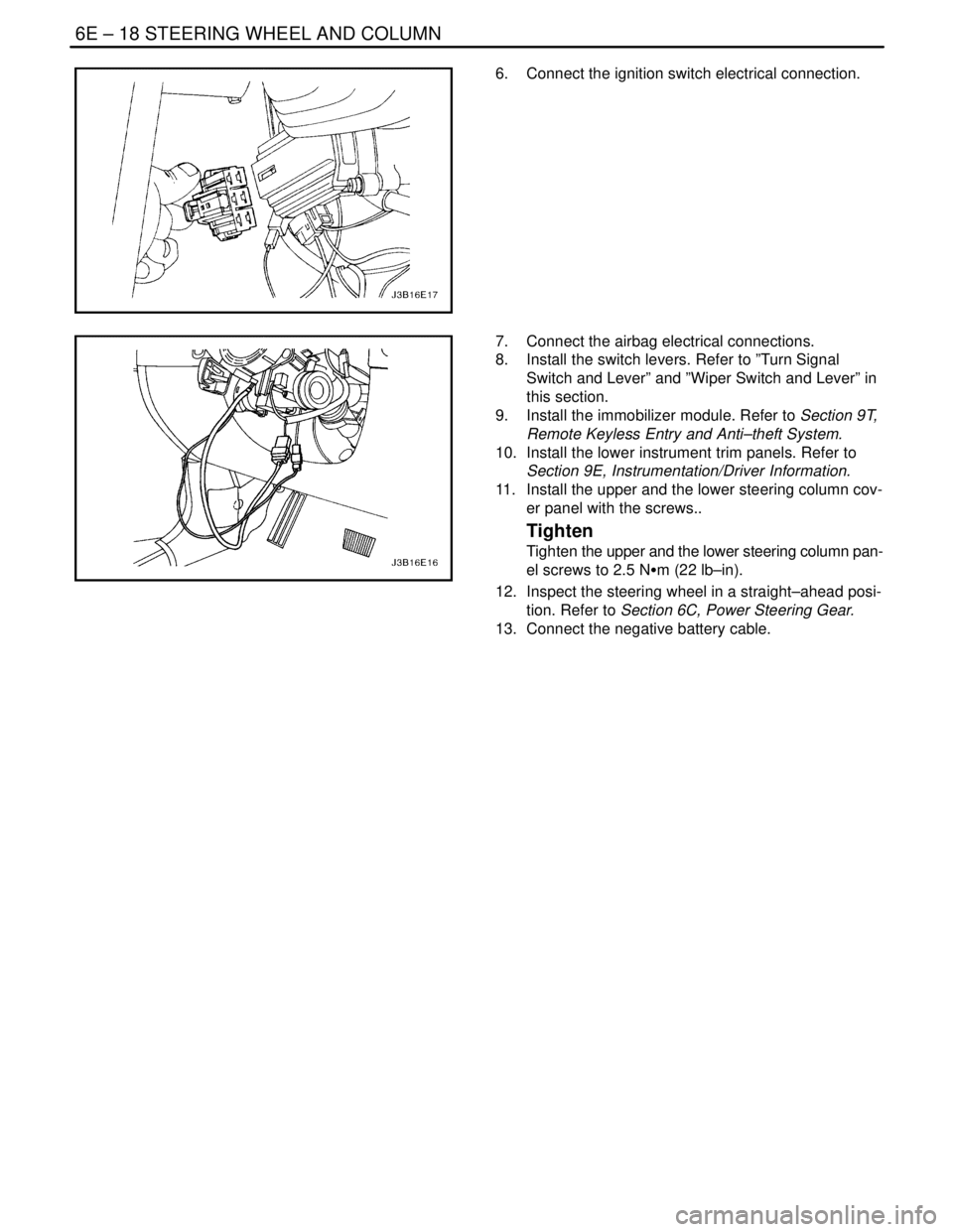
6. Connect the ignition switch electrical connection.
7. Connect the airbag electrical connections.
8. Install the switch levers. Refer to ”Turn Signal
Switch and Lever” and ”Wiper Switch and Lever” in
this section.
9. Install the immobilizer module. Refer to Section 9T,
Remote Keyless Entry and Anti–theft System.
10. Install the lower instrument trim panels. Refer to
Section 9E, Instrumentation/Driver Information.
11. Install the upper and the lower steering column cov-
er panel with the screws..
Tighten
Tighten the upper and the lower steering column pan-
el screws to 2.5 NSm (22 lb–in).
12. Inspect the steering wheel in a straight–ahead posi-
tion. Refer to Section 6C, Power Steering Gear.
13. Connect the negative battery cable.
Page 1974 of 2643

6E – 20ISTEERING WHEEL AND COLUMN
DAEWOO V–121 BL4
GENERAL DESCRIPTION
AND SYSTEM OPERATION
STEERING WHEEL AND COLUMN
CAUTION : To ensure the energy–absorbing action of
the steering column, it is important to use only the
specified screws, bolts, and nuts, tightened to the
specified torque.
In addition to the steering function, the steering column
provides safety and security.
The energy–absorbing column is designed to compress in
a front–end collision to lessen the chance of driver injury.
The ignition switch and the lock are mounted on the col-
umn, allowing the ignition and steering operations to be
locked to inhibit theft of the car.
The column levers trigger the turn signals, the headlight
beams, and the windshield washer and wipers.The tilt steering column uses telescopic function to allow
the steering wheel to tilt up and down in and out. This en-
ables the driver to adjust the steering wheel to a comfort-
able position.
Notice : Apply a thin coat of lithium grease to all friction
points when reassembling.
The column may be disassembled and reassembled easi-
ly.IGNITION KEY REMINDER
The ignition key reminder alerts the driver that the key is
still in the ignition when the driver attempts to exit the ve-
hicle.
An internal switch in the ignition lock cylinder supplies bat-
tery voltage to the reminder chime module when all of the
following conditions are true:
S The key is in the ignition switch.
S The ignition is OFF.
S The driver’s door is open.
For information on removal and installation of the reminder
chime module, refer to Section 9E, Instrumentation/Driver
Information.
Page 1992 of 2643
7A – 18IHEATING AND VENTILATION SYSTEM
DAEWOO V–121 BL4
MAINTENANCE AND REPAIR
ON–VEHICLE SERVICE
TEMPERATURE CABLE
ADJUSTMENT
Because the cable and the cable housings have fixed
lengths, it is impossible to make a temperature cable ad-
justment.
In addition, the heater/air distributor case linkage cannot
be adjusted.
If a malfunction is suspected, verify the proper operation
of the controller and the mechanical doors for the heater/
air distributor case assembly.
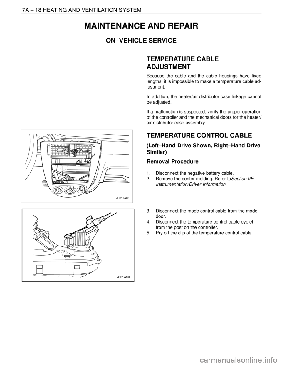
TEMPERATURE CONTROL CABLE
(Left–Hand Drive Shown, Right–Hand Drive
Similar)
Removal Procedure
1. Disconnect the negative battery cable.
2. Remove the center molding. Refer toSection 9E,
Instrumentation/Driver Information.
3. Disconnect the mode control cable from the mode
door.
4. Disconnect the temperature control cable eyelet
from the post on the controller.
5. Pry off the clip of the temperature control cable.