Page 2042 of 2643
7B – 40IMANUAL CONTROL HEATING, VENTILATION AND AIR CONDITIONING SYSTEM
DAEWOO V–121 BL4
11. Remove the compressor from the bench vise and
remove the J–34992 compressor holding fixture
from the compressor.
12. Install the compressor. Refer to ”Compressor” in
this section.
CLUTCH ROTOR AND BEARING
Tools Required
J–6083 Snap Ring Pliers
J–9398–A Bearing Remover
J–9481 Bearing Installer
J–33020 Pulley Puller
J–33023–A Puller Pilot
J–33019 Bearing Staking Tool Set
Includes: J–33019–1 Bearing Staking Guide
Includes: J–33019–2 Bearing Staking Pin
Includes: J–33019–1 Bearing Staking Guide
J–33017 Pulley Rotor and Bearing Installer
J–8433–1 Puller Crossbar
J–34992 Compressor Holding Fixture
J–8092 Driver Handle
J–8433–3 Forcing Screw
Disassembly Procedure
1. Disconnect the negative battery cable.
2. Recover the refrigerant. Refer to ”Discharging,
Adding Oil, Evacuating, and Charging for A/C Sys-
tem” in this section.
3. Remove the compressor. Refer to ”Compressor” in
this section.
4. Remove the clutch drive plate and hub assembly.
Refer to ”Clutch Plate and Hub Assembly” in this
section.
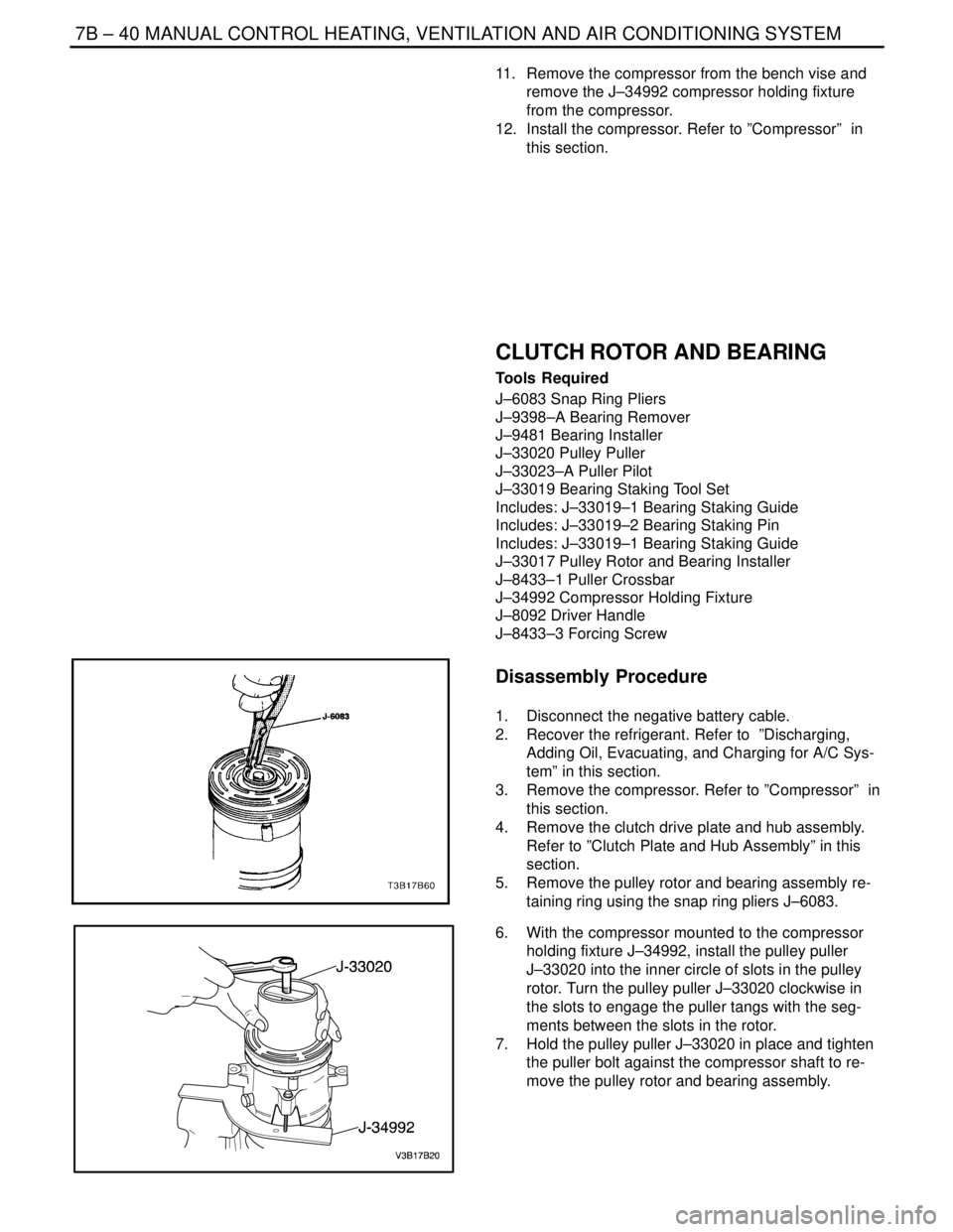
5. Remove the pulley rotor and bearing assembly re-
taining ring using the snap ring pliers J–6083.
6. With the compressor mounted to the compressor
holding fixture J–34992, install the pulley puller
J–33020 into the inner circle of slots in the pulley
rotor. Turn the pulley puller J–33020 clockwise in
the slots to engage the puller tangs with the seg-
ments between the slots in the rotor.
7. Hold the pulley puller J–33020 in place and tighten
the puller bolt against the compressor shaft to re-
move the pulley rotor and bearing assembly.
Page 2043 of 2643
MANUAL CONTROL HEATING, VENTILATION AND AIR CONDITIONING SYSTEM 7B – 41
DAEWOO V–121 BL4
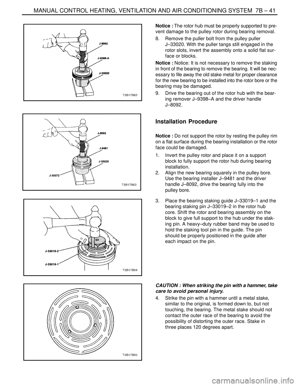
Notice : The rotor hub must be properly supported to pre-
vent damage to the pulley rotor during bearing removal.
8. Remove the puller bolt from the pulley puller
J–33020. With the puller tangs still engaged in the
rotor slots, invert the assembly onto a solid flat sur-
face or blocks.
Notice : Notice: It is not necessary to remove the staking
in front of the bearing to remove the bearing. It will be nec-
essary to file away the old stake metal for proper clearance
for the new bearing to be installed into the rotor bore or the
bearing may be damaged.
9. Drive the bearing out of the rotor hub with the bear-
ing remover J–9398–A and the driver handle
J–8092.
Installation Procedure
Notice : Do not support the rotor by resting the pulley rim
on a flat surface during the bearing installation or the rotor
face could be damaged.
1. Invert the pulley rotor and place it on a support
block to fully support the rotor hub during bearing
installation.
2. Align the new bearing squarely in the pulley bore.
Use the bearing installer J–9481 and the driver
handle J–8092, drive the bearing fully into the
pulley bore.
3. Place the bearing staking guide J–33019–1 and the
bearing staking pin J–33019–2 in the rotor hub
core. Shift the rotor and bearing assembly on the
block to give full support to the hub under the stak-
ing pin. A heavy–duty rubber band may be used to
hold the staking tool pin in the guide. The pin
should be properly positioned in the guide after
each impact on the pin.
CAUTION : When striking the pin with a hammer, take
care to avoid personal injury.
4. Strike the pin with a hammer until a metal stake,
similar to the original, is formed down to, but not
touching, the bearing. The metal stake should not
contact the outer race of the bearing to avoid the
possibility of distorting the outer race. Stake in
three places 120 degrees apart.
Page 2062 of 2643
AUTOMATIC TEMPERATURE CONTROL HEATING, VENTILATION, AND AIR CONDITIONING SYSTEM 7D – 7
DAEWOO V–121 BL4
CONTROLLER DOES NOT ILLUMINATE WHEN LIGHT
SWITCH IS ON
StepActionValue(s)YesNo
1Check other instrumentation lights.
Are those lights also off?–Go to Section
9E, Instrumen-
tation/Driver In-
formationGo to Step 2
21. Remove the controller.
2. Check the voltage between terminals A3 and
A4 of the controller connector.
Is the voltage within the specified value?11–14 vGo to Step 4Go to Step 3
3Repair the wiring harness between splice S204 and
controller connector terminal A4 or between splice
S203 and controller connector terminal A3.
Is the repair complete?–System OK–
4Check the illumination lamps.
Is one burned out?–Go to Step 5Go to Step 6
5Replace the burned out illumination lamp.
Is the repair complete?–System OK–
Page 2088 of 2643
IAUTOMATIC TEMPERATURE CONTROL HEATING, VENTILATION, AND AIR CONDITIONING SYSTEM 7D – 33
DAEWOO V–121 BL4
SERVICEABLE COMPONENTS
COMMON HVAC COMPONENTS
Those components used in non–automatic systems are
covered in other sections of this manual.
Refer to Section 7A, Heating and Ventilation System for
the following procedures:
S Blower Motor.
S Heater Hoses.
S Blower Resistor.
S High–Blower Relay.
S Heater/Air Distributor Case Assembly (A/C Mod-
ule).
S Heater Core.
Refer to Section 7B, Manual Control Heating, Ventilation,
and Air Conditioning System, for the following proce-
dures:
S A/C Pressure Transducer.
S A/C Compressor Relay.
S Air Filter.
S A/C Expansion Valve.
S A/C High–Pressure Pipe Line.
S Evaporator Core.
S A/C Suction Hose Assembly.
S A/C Discharge Hose–Compressor to Condenser.
S Compressor.
S Condenser.
S Receiver–Dryer.
AUTOMATIC TEMPERATURE
CONTROL ASSEMBLY
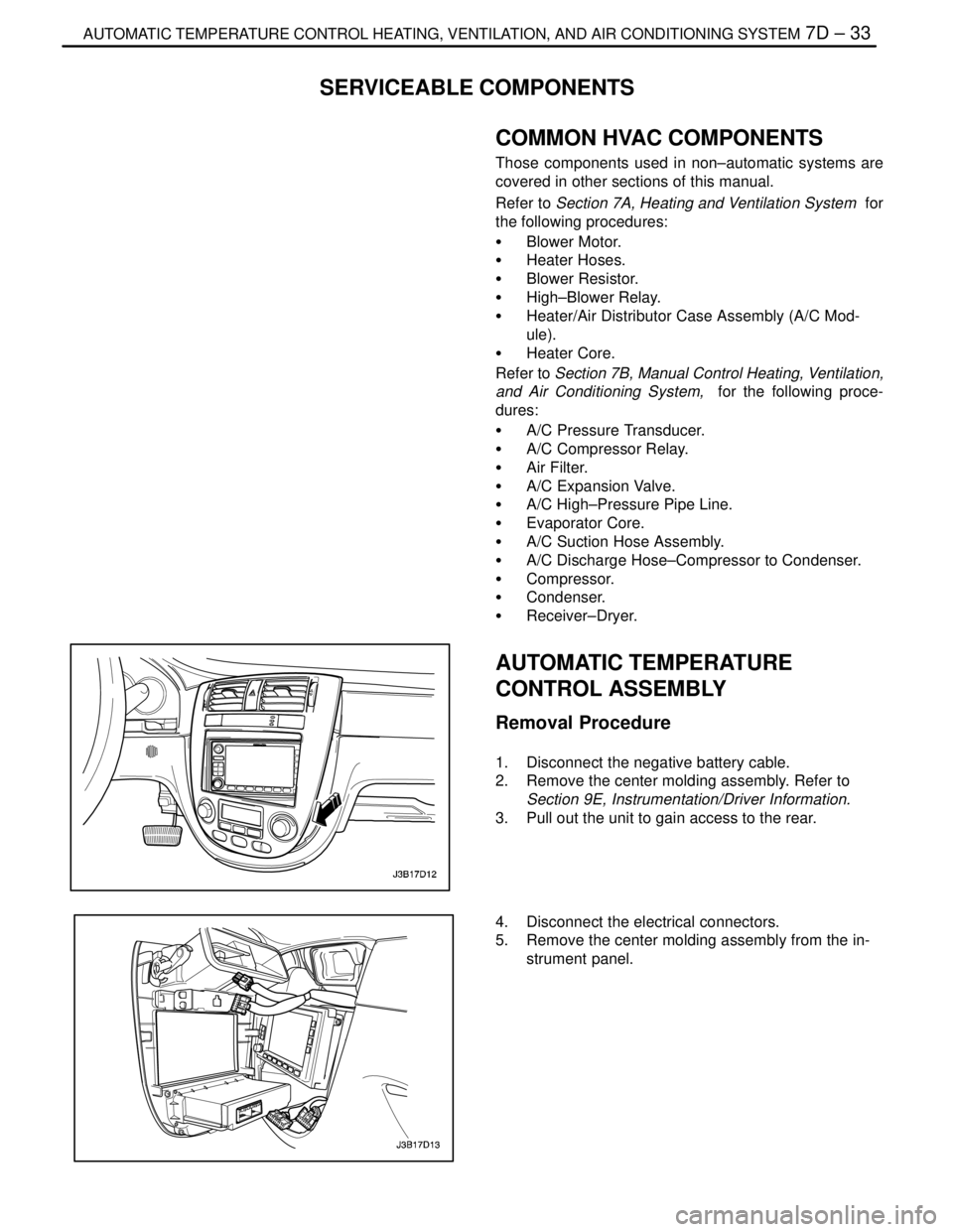
Removal Procedure
1. Disconnect the negative battery cable.
2. Remove the center molding assembly. Refer to
Section 9E, Instrumentation/Driver Information.
3. Pull out the unit to gain access to the rear.
4. Disconnect the electrical connectors.
5. Remove the center molding assembly from the in-
strument panel.
Page 2089 of 2643
7D – 34IAUTOMATIC TEMPERATURE CONTROL HEATING, VENTILATION, AND AIR CONDITIONING SYSTEM
DAEWOO V–121 BL4
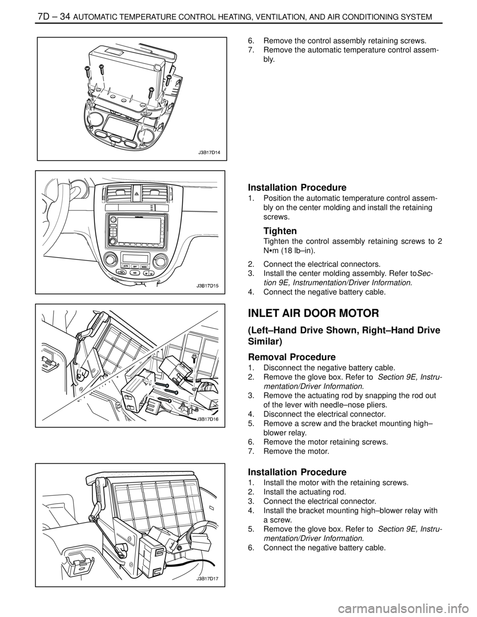
6. Remove the control assembly retaining screws.
7. Remove the automatic temperature control assem-
bly.
Installation Procedure
1. Position the automatic temperature control assem-
bly on the center molding and install the retaining
screws.
Tighten
Tighten the control assembly retaining screws to 2
NSm (18 lb–in).
2. Connect the electrical connectors.
3. Install the center molding assembly. Refer toSec-
tion 9E, Instrumentation/Driver Information.
4. Connect the negative battery cable.
INLET AIR DOOR MOTOR
(Left–Hand Drive Shown, Right–Hand Drive
Similar)
Removal Procedure
1. Disconnect the negative battery cable.
2. Remove the glove box. Refer to Section 9E, Instru-
mentation/Driver Information.
3. Remove the actuating rod by snapping the rod out
of the lever with needle–nose pliers.
4. Disconnect the electrical connector.
5. Remove a screw and the bracket mounting high–
blower relay.
6. Remove the motor retaining screws.
7. Remove the motor.
Installation Procedure
1. Install the motor with the retaining screws.
2. Install the actuating rod.
3. Connect the electrical connector.
4. Install the bracket mounting high–blower relay with
a screw.
5. Remove the glove box. Refer to Section 9E, Instru-
mentation/Driver Information.
6. Connect the negative battery cable.
Page 2090 of 2643
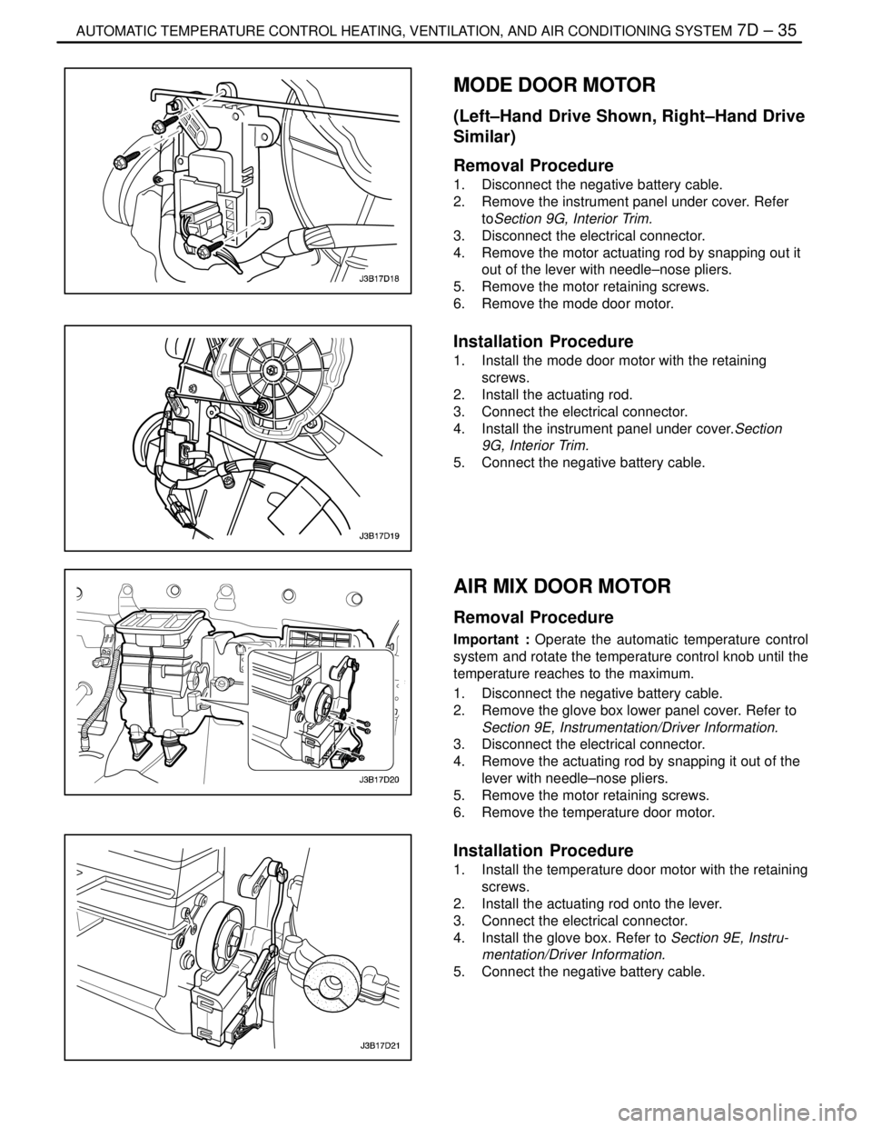
IAUTOMATIC TEMPERATURE CONTROL HEATING, VENTILATION, AND AIR CONDITIONING SYSTEM 7D – 35
DAEWOO V–121 BL4
MODE DOOR MOTOR
(Left–Hand Drive Shown, Right–Hand Drive
Similar)
Removal Procedure
1. Disconnect the negative battery cable.
2. Remove the instrument panel under cover. Refer
toSection 9G, Interior Trim.
3. Disconnect the electrical connector.
4. Remove the motor actuating rod by snapping out it
out of the lever with needle–nose pliers.
5. Remove the motor retaining screws.
6. Remove the mode door motor.
Installation Procedure
1. Install the mode door motor with the retaining
screws.
2. Install the actuating rod.
3. Connect the electrical connector.
4. Install the instrument panel under cover.Section
9G, Interior Trim.
5. Connect the negative battery cable.
AIR MIX DOOR MOTOR
Removal Procedure
Important : Operate the automatic temperature control
system and rotate the temperature control knob until the
temperature reaches to the maximum.
1. Disconnect the negative battery cable.
2. Remove the glove box lower panel cover. Refer to
Section 9E, Instrumentation/Driver Information.
3. Disconnect the electrical connector.
4. Remove the actuating rod by snapping it out of the
lever with needle–nose pliers.
5. Remove the motor retaining screws.
6. Remove the temperature door motor.
Installation Procedure
1. Install the temperature door motor with the retaining
screws.
2. Install the actuating rod onto the lever.
3. Connect the electrical connector.
4. Install the glove box. Refer to Section 9E, Instru-
mentation/Driver Information.
5. Connect the negative battery cable.
Page 2096 of 2643

SECTION : 8A
SEAT BELTS
CAUTION : Disconnect the negative battery cable before removing or installing any electrical unit or when a tool
or equipment could easily come in contact with exposed electrical terminals. Disconnecting this cable will help
prevent personal injury and damage to the vehicle. The ignition must also be in LOCK unless otherwise noted.
TABLE OF CONTENTS
SPECIFICATIONS8A–1 . . . . . . . . . . . . . . . . . . . . . . . . . .
Fastener Tightening Specifications 8A–1. . . . . . . . . . .
SCHEMATIC AND ROUTING DIAGRAMS8A–2 . . . . .
Driver Seat Belt Warning 8A–2. . . . . . . . . . . . . . . . . . . .
DIAGNOSIS8A–3 . . . . . . . . . . . . . . . . . . . . . . . . . . . . . . . .
Driver Seat Belt Warning 8A–3. . . . . . . . . . . . . . . . . . . .
MAINTENANCE AND REPAIR8A–4 . . . . . . . . . . . . . . .
ON–VEHICLE SERVICE 8A–4. . . . . . . . . . . . . . . . . . . . .
Pretensioner Front Seat Belt 8A–4. . . . . . . . . . . . . . . .
Front Seat Belt Height Adjuster 8A–5. . . . . . . . . . . . . . Three–Point Rear Seat Belt (LH,CENTER, RH) 8A–6
Front Seat Belt Buckle 8A–7. . . . . . . . . . . . . . . . . . . . .
GENERAL DESCRIPTION AND SYSTEM
OPERATION 8A–9 . . . . . . . . . . . . . . . . . . . . . . . . . . . . .
Driver Seat Belt Warning 8A–9. . . . . . . . . . . . . . . . . . . .
Three–Point ELR Front Seat Belt With
Pretensioner 8A–9. . . . . . . . . . . . . . . . . . . . . . . . . . . .
Three–Point CLR (ELR) Rear Outboard Seat
Belt 8A–9. . . . . . . . . . . . . . . . . . . . . . . . . . . . . . . . . . . .
Operational and Functional Checks 8A–9. . . . . . . . . .
Child Seat Tether Anchor 8A–9. . . . . . . . . . . . . . . . . . .
SPECIFICATIONS
FASTENER TIGHTENING SPECIFICATIONS
ApplicationNSmLb–FtLb–In
Child Seat Tether Anchor Bolt2518–
Front Seat Belt Height Adjuster Bolts2317–
Seat Belt Anchor Bolt3828–
Seat Belt Retractor Bracket Screws3–27
Seat Belt Retractor Bolt3828–
Page 2097 of 2643
8A – 2ISEAT BELTS
DAEWOO V–121 BL4
SCHEMATIC AND ROUTING DIAGRAMS
DRIVER SEAT BELT WARNING