Page 1342 of 2643
5–182WELECTRICAL WIRING DIAGRAMS
30. SSPS (SPEED SENSITIVE POWER STEERING) CIRCUITa. CONNECTOR INFORMATION
CONNECTOR(NO.)
(PIN NO. COLOR)
CONNECTING, WIRING HARNESSCONNECTOR POSITION
C102 (11 Pin, White)Body � Engine Fuse BlockEngine Fuse Block
C106 (20 Pin, White)Engine � Engine Fuse BlockEngine Fuse Block
C108 (24 Pin, Black)Body � EngineLeft Engine Fuse Block
C113 (16 Pin, Black)Body � FrontBehind ECM Bracket
C201 (76 Pin, Black)I.P � I.P Fuse BlockI.P Fuse Block
C202 (89 Pin, White)I.P � BodyLeft CO–Driver Leg Room
C206 (22 Pin, White)I.P � TCMUpper Driver Leg Room
S202 (Black)I.PBehind Cluster
S203 (Red)I.PBehind Audio Mounting
G104EngineUnder Start Motor
G203I.PBehind Left Audio Bracket
b. CONNECTOR IDENTIFICATION SYMBOL & PIN NUMBER POSITION
Page 1344 of 2643
5–184WELECTRICAL WIRING DIAGRAMS
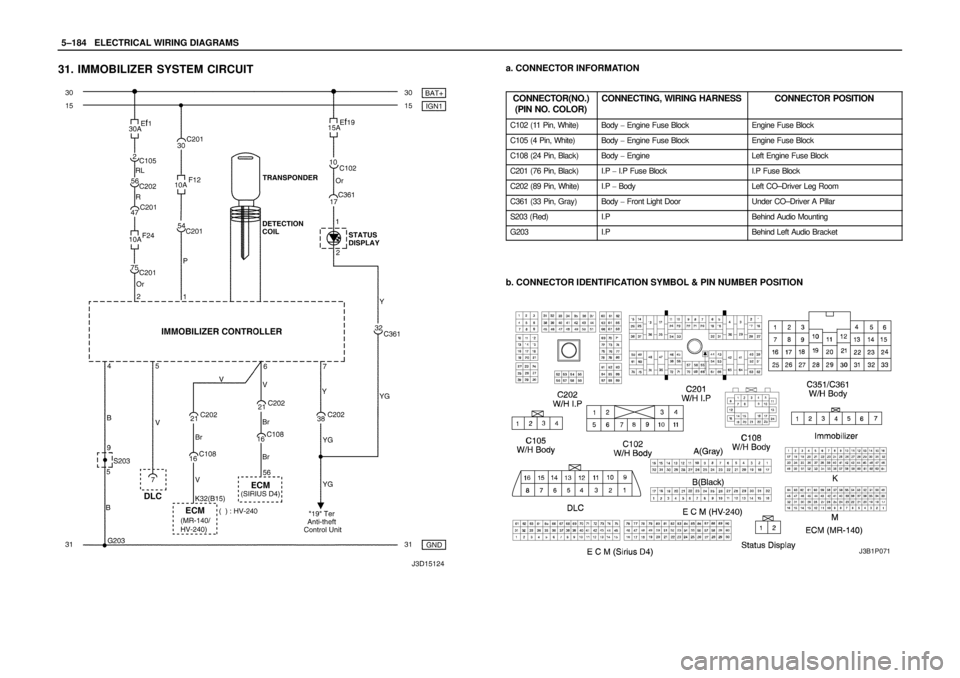
31. IMMOBILIZER SYSTEM CIRCUITa. CONNECTOR INFORMATION
CONNECTOR(NO.)
(PIN NO. COLOR)
CONNECTING, WIRING HARNESSCONNECTOR POSITION
C102 (11 Pin, White)Body � Engine Fuse BlockEngine Fuse Block
C105 (4 Pin, White)Body � Engine Fuse BlockEngine Fuse Block
C108 (24 Pin, Black)Body � EngineLeft Engine Fuse Block
C201 (76 Pin, Black)I.P � I.P Fuse BlockI.P Fuse Block
C202 (89 Pin, White)I.P � BodyLeft CO–Driver Leg Room
C361 (33 Pin, Gray)Body � Front Light DoorUnder CO–Driver A Pillar
S203 (Red)I.PBehind Audio Mounting
G203I.PBehind Left Audio Bracket
b. CONNECTOR IDENTIFICATION SYMBOL & PIN NUMBER POSITION
J3B1P071
Page 1346 of 2643
 NOTCH BACK
a. CONNECTOR INFORMATION
CONNECTOR(NO.)
(PIN NO. COLOR)
CONNECTING, WIRING HARNESSCONNECTOR POSITION
C102 (11 Pin")
5–186WELECTRICAL WIRING DIAGRAMS
32. ANTI THEFT CONTROL SYSTEM CIRCUIT
1) NOTCH BACK
a. CONNECTOR INFORMATION
CONNECTOR(NO.)
(PIN NO. COLOR)
CONNECTING, WIRING HARNESSCONNECTOR POSITION
C102 (11 Pin, White)Body � Engine Fuse BlockEngine Fuse Block
C104 (24 Pin, White)Front � Engine Fuse BlockEngine Fuse Block
C105 (4 Pin, White)Body � Engine Fuse BlockEngine Fuse Block
C113 (16 Pin, Black)Body � FrontBehind ECM Bracket
C201 (76 Pin, Black)I.P � I.P Fuse BlockI.P Fuse Block
C202 (89 Pin, White)I.P � BodyLeft CO–Driver Leg Room
C351 (33 Pin, Gray)Body � Front Light DoorUnder CO–Driver A Pillar
C361 (33 Pin, Gray)Body � Front Right DoorUnder Driver A Pillar
C402 (8 Pin, White)Trunk LID � BodyInside Right Trunk Side Cover
S202 (Black)I.PBehind Cluster
S301 (Blue)BodyLeft CO–Driver Leg Room
S302 (Brown)BodyLeft CO–Driver Leg Room
G301BodyBelow Driver Cross Member Floor Panel
G302BodyBelow Left C Pillar
G303BodyBelow Left CO–Driver Leg Room
b. CONNECTOR IDENTIFICATION SYMBOL & PIN NUMBER POSITION
Page 1348 of 2643
 HATCH BACKa. CONNECTOR INFORMATION
CONNECTOR(NO.)
(PIN NO. COLOR)
CONNECTING, WIRING HARNESSCONNECTOR POSITION
C102 (11 Pin, White)Body � Engine Fuse BlockEngine")
5–188WELECTRICAL WIRING DIAGRAMS
2) HATCH BACKa. CONNECTOR INFORMATION
CONNECTOR(NO.)
(PIN NO. COLOR)
CONNECTING, WIRING HARNESSCONNECTOR POSITION
C102 (11 Pin, White)Body � Engine Fuse BlockEngine Fuse Block
C104 (24 Pin, White)Front � Engine Fuse BlockEngine Fuse Block
C105 (4 Pin, White)Body � Engine Fuse BlockEngine Fuse Block
C113 (16 Pin, Black)Body � FrontBehind ECM Bracket
C201 (76 Pin, Black)I.P � I.P Fuse BlockI.P Fuse Block
C202 (89 Pin, White)I.P � BodyLeft CO–Driver Leg Room
C351 (33 Pin, Gray)Body � Front Light DoorUnder CO–Driver A Pillar
C361 (33 Pin, Gray)Body � Front Right DoorUnder Driver A Pillar
C404 (8 Pin, White)T/Gate. EXT. � BodyInside Left C Pillar
C405 (8 Pin, White)T/Gate. EXT. � T/GateBeside Left Rear Wiper Motor
C406 (6 Pin, White)T/Gate. EXT. � T/GateBeside Left Rear Wiper Motor
S202 (Black)I.PBehind Cluster
S301 (Blue)BodyLeft CO–Driver Leg Room
S302 (Brown)BodyLeft CO–Driver Leg Room
G301BodyBelow Driver Cross Member Floor Panel
G302BodyBelow Left C Pillar
G303BodyBelow Left CO–Driver Leg Room
G402T/Gate. EXT.Inside Driver C Pillar
b. CONNECTOR IDENTIFICATION SYMBOL & PIN NUMBER POSITION
Page 1525 of 2643
 P1871
EDS VALVE POWER SUPPLY CIRCUIT SHORTED TO
POWER
Circuit Description
The pressure control valves (EDS va")
5A1 – 176IZF 4 HP 16 AUTOMATIC TRANSAXLE
DAEWOO V–121 BL4
DIAGNOSTIC TROUBLE CODE(DTC) P1871
EDS VALVE POWER SUPPLY CIRCUIT SHORTED TO
POWER
Circuit Description
The pressure control valves (EDS valves 3,4,5 and 6) are
precision electronic pressure regulators that control the
operation of the clutches, brakes and lock–up clutch.
The valve reduces the system pressure with which the
downstream solenoid valves and electrical pressure regu-
lating valves are supplied. It is possible to use smaller so-
lenoid valves as a result. The EDS require a constant input
pressure.
Conditions for Setting the DTC
S If the voltage applied to high side driver is higher
than the threshold(6V) with high side driver switch
off status then a fault is detected.
S No DTC P1870.
S Immediately after the above condition occurs.
Action Taken When The DTC SetsS The Malfunction Indicator Lamp(MIL) will illuminate.
S The TCM will record operating conditions at the
time the diagnostic fails. This information will be
stored in the Failure Records buffer.
S Adopt Emergency/ Substitute mode and constant
4th gear by hydraulic control.
S After ignition OFF/ON : 3rd gear by hydraulic con-
trol. Possible P, R and N also possible.
S Power supply cut off to the EDS valve.
Conditions for Clearing the MIL/DTC
S The MIL will turn OFF when the malfunction has
not occurred after three–ignition cycle.
S A history DTC will clear after 40 consecutive warm
up cycles without a fault.
S Using a scan tool can clear history DTCs.
Diagnostic Aids
S When DTC P1871 sets, the possible cause of fault
could be EDS valve power supply line.
Page 1550 of 2643

ZF 4 HP 16 AUTOMATIC TRANSAXLE 5A1 – 201
DAEWOO V–121 BL4
DRIVE AXLE OIL SEAL
Removal Procedure
1. Disconnect the negative battery cable.
2. Remove the drive axles. Refer to Section 3A, Auto-
matic Transaxle Drive Axle.
Notice : Be careful not to damage the bore of the transaxle
case.
3. Remove the transaxle drive seal using a screwdriv-
er. If necessary, crush the seal first with the screw-
driver in order to loosen the seal from the case.
Tools Required
DW260–030 Axle Seal Installer
Installation Procedure
1. Install the transaxle drive seal using the axle seal
installer DW260–030.
2. Install the drive axles. Refer to Section 3A, Auto-
matic Transaxle Drive Axle.
3. Connect the negative battery cable.
OIL PAN, OIL PAN GASKET
Tools Required
DW260–070 Plug Remover/Installer
Removal Procedure
1. Disconnect the negative battery cable.
2. Raise and suitably support the vehicle.
3. Remove the engine under cover. Refer to Section
9N, Frame and Underbody.
4. Place a fluid container below the fluid drain plug.
5. Remove the transaxle fluid drain plug using the
plug remover/installer DW260–070 and drain the
transaxle fluid.
6. Remove the oil cooler inlet and outlet pipes. Refer
to ”Oil Cooler Pipe/Hose” in this section.
Page 1585 of 2643

5A1 – 236IZF 4 HP 16 AUTOMATIC TRANSAXLE
DAEWOO V–121 BL4
ELECTRONICAL COMPONENTS
Selector Lever/Program Switch
The driver engages the travel position via the selector le-
ver:
P : Park Position
R : Reverse
N : Neutral
D : Forward Speeds
Park/Neutral Position Switch
The Park/Neutral Position Switch is located on the selec-
tor shaft and informs the TCM of the current selector lever
position P–R–N–D–3–2–1.
The selector lever position is transmitted to the TCM in en-
coded form along 4 lines. The encoding is such that mal-
functions in the connecting lead are identified.
The Park/Neutral Position Switch is located on the selec-
tor shaft, which is connected to the selector lever via a pull
cable. In addition, the Park/Neutral Position Switch con-
trols the starter interlock, the reversing light and the selec-
tor lever position indicator on the instrument panel.
Signal Combination
L1L2L3L4
P00120
R00012
N01200
D1212120
31212012
21201212
10121212
Automatic Transaxle Output Speed Sensor
(A/T OSS)
The vehicle A/T OSS is a magnetic inductive pickup that
relays information relative to vehicle speed to the TCM.
Vehicle speed information is used by the TCM to control
shift timing, line pressure, and TCC (lock–up clutch) apply
and release.
The output speed sensor mounts in the case at the speed
sensor rotor, which is pressed onto the spur gear. An air
gap of 0.1mm~1.3mm(0.004~0.05in) is maintained be-
tween the sensor and the teeth on the spur gear teeth. The
sensor consists of a permanent magnet surrounded by a
coil of wire.
As the differential rotates, an AC signal is generated by the
output speed sensor (OSS).
Automatic Transaxle Input Speed Sensor
(A/T ISS)
The A/T ISS is a magnetic inductive pickup that relays in-
formation relative to transaxle input speed to the TCM.
The TCM uses transaxle input speed information to con-
trol line pressure, TCC apply and release and transaxle
shift patterns. This information is also uses to calculate the
appropriate operating gear ratios and TCC slippage.
The input speed sensor mounts onto piston B that is inside
of valve body.
An air gap of 1.8~2.2mm(0.07~0.086inch) is maintained
between the sensor and the piston B.
The sensor consists of a permanent magnet surrounded
by a coil of wire. As the piston B is driven by the turbine
shaft, an AC signal induced in the input speed sensor.
Higher vehicle speeds induce a higher frequency and volt-
age measurement at the sensor.
Sensor resistance should measure between 825~835
ohms at 20°C (68°F). Sensor can measure from
1,000~8,000HZ.
Page 1588 of 2643

ZF 4 HP 16 AUTOMATIC TRANSAXLE 5A1 – 239
DAEWOO V–121 BL4
S Excessive transaxle fluid leaking into the connector,
wicking up into the external wiring harness, and
degrading the wire insulation.
S Water/moisture intrusion in the connector.
S Low pin retention in the external connector from
excessive connection and disconnection of the wir-
ing connector assembly.
S Pin corrosion from contamination.
S Broken/cracked connector assembly.
S Points to remember when working with transaxle
wiring connector assembly.
S To remove the connector, squeeze the two tabs
towards each other and pull straight up (refer to
illustration).Carefully limit twisting or wiggling the connector during re-
moval. Bent pins can occur.
DO NOT pry the connector off with a screwdriver or other
tool.
To reinstall the external wiring connector, first orient the
pins by lining up arrows on each half of the connector.
Push the connector straight down into the transaxle with-
out twisting or angling the mating parts.
The connector should click into place with a positive feel
and/or noise.
Transaxle Control Module (TCM)
The transaxle control module (TCM) is an electronic de-
vice which monitors inputs to control various transaxle
functions including shift quality and transaxle sensors,
switches, and components to process for use within its’
control program. Based on this input information, the TCM
controls various transaxle output functions and devices.
Data Link Connector (DLC)
The data link connector (DLC) is a multiple cavity connec-
tor. The DLC provides the means to access serial data
from the TCM to aid in powertrain diagnosis. The DLC al-
lows the technician to use a scan tool to monitor various
systems and display diagnostic trouble codes (DTCs).
The DLC connector is located within the driver’s compart-
ment, directly below the steering column.
 CIRCUITa. CONNECTOR INFORMATION
CONNECTOR(NO.)
(PIN NO. COLOR)
CONNECTING, WIRING HARNESSCONNECTOR POSITION
C102 (11 Pin, W")