Page 1632 of 2585
(24) Obtain helper and transmission jack. Secure
transaxle to transmission jack and remove transaxle-
to-engine bolts.
(25) Remove transaxle from engine (Fig. 25).
(26) Inspect clutch, clutch release components, and
flywheel.
DISASSEMBLY
(1) Remove clutch release lever and bearing (Fig.
26). Inspect release lever pivot balls and replace if
necessary (Fig. 27). Use slide hammer C-3752 and
remover/installer 6891 (Fig. 28) if pivot ball replace-
ment is necessary.
Fig. 22 Left Mount Bracket Removal/Installation
1 - BOLT (2)
2 - MOUNT BRACKET
3 - BOLT (2)
Fig. 23 Starter Motor Removal/Installation
1 - STARTER MOTOR
2 - BOLT (3)
Fig. 24 Transaxle Upper Mount
1 - MOUNT
2 - BOLT (4)
RST850 MANUAL TRANSAXLE21-35
T850 MANUAL TRANSAXLE (Continued)
Page 1637 of 2585

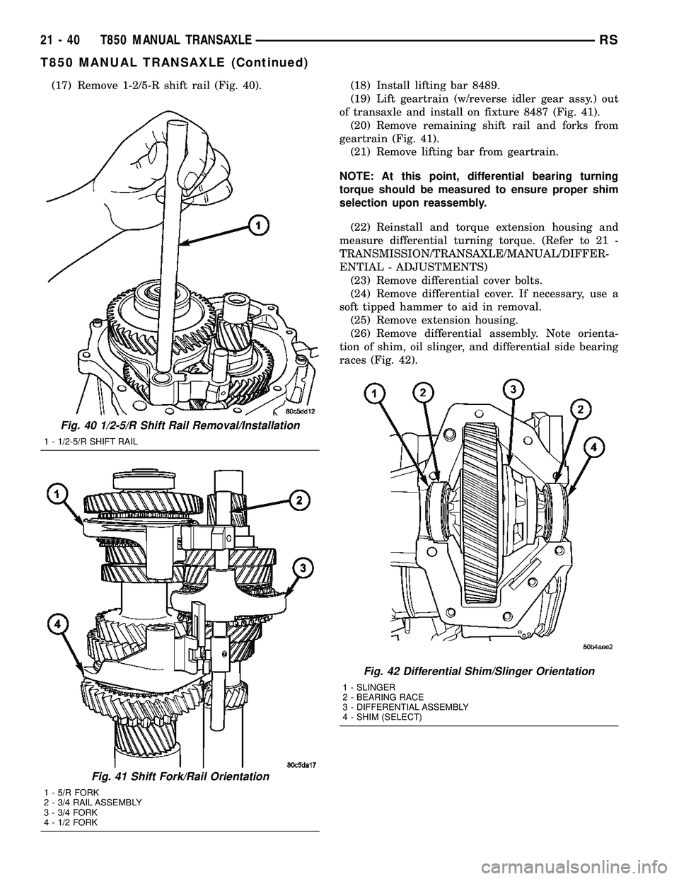
(17) Remove 1-2/5-R shift rail (Fig. 40). (18) Install lifting bar 8489.
(19) Lift geartrain (w/reverse idler gear assy.) out
of transaxle and install on fixture 8487 (Fig. 41).
(20) Remove remaining shift rail and forks from
geartrain (Fig. 41).
(21) Remove lifting bar from geartrain.
NOTE: At this point, differential bearing turning
torque should be measured to ensure proper shim
selection upon reassembly.
(22) Reinstall and torque extension housing and
measure differential turning torque. (Refer to 21 -
TRANSMISSION/TRANSAXLE/MANUAL/DIFFER-
ENTIAL - ADJUSTMENTS)
(23) Remove differential cover bolts.
(24) Remove differential cover. If necessary, use a
soft tipped hammer to aid in removal.
(25) Remove extension housing.
(26) Remove differential assembly. Note orienta-
tion of shim, oil slinger, and differential side bearing
races (Fig. 42).
Fig. 40 1/2-5/R Shift Rail Removal/Installation
1 - 1/2-5/R SHIFT RAIL
Fig. 41 Shift Fork/Rail Orientation
1 - 5/R FORK
2 - 3/4 RAIL ASSEMBLY
3 - 3/4 FORK
4 - 1/2 FORK
Fig. 42 Differential Shim/Slinger Orientation
1 - SLINGER
2 - BEARING RACE
3 - DIFFERENTIAL ASSEMBLY
4 - SHIM (SELECT)
21 - 40 T850 MANUAL TRANSAXLERS
T850 MANUAL TRANSAXLE (Continued)
Page 1639 of 2585
ASSEMBLY
NOTE: When assembling this transaxle, always use
NEW snap rings.
NOTE: Before assembling transaxle, differential
turning torque must be measured and adjusted.
(Refer to 21 - TRANSMISSION/TRANSAXLE/MANU-
AL/DIFFERENTIAL - ADJUSTMENTS). Differential
turning torque must be measured with geartrain out
of case.
(1) Install input shaft bearing using an arbor press
and remover/installer 8474 (Fig. 47).
(2) Install shift shaft bushing to case using
installer 8475 (Fig. 48).
Fig. 46 Input Shaft Bearing Removal
1 - ARBOR PRESS
2 - DRIVER HANDLE C-4171
3 - REMOVER/INSTALLER 8474
Fig. 47 Input Shaft Bearing Installation
1 - ARBOR PRESS
2 - C-4171 DRIVER HANDLE
3 - REMOVER/INSTALLER 8474
4 - INPUT SHAFT BEARING
Fig. 48 Shift Shaft Bushing Installation
1 - INSTALLER 8475
2 - SHIFT SHAFT BUSHING
21 - 42 T850 MANUAL TRANSAXLERS
T850 MANUAL TRANSAXLE (Continued)
Page 1640 of 2585

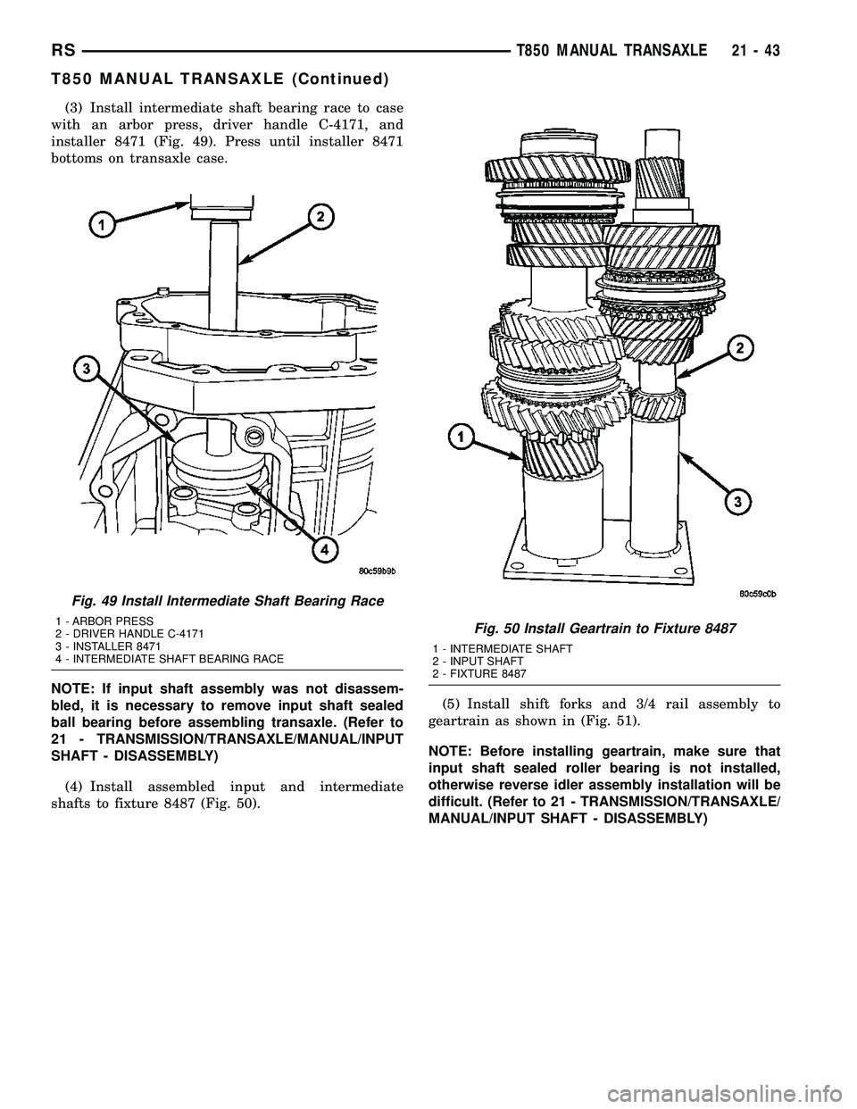
(3) Install intermediate shaft bearing race to case
with an arbor press, driver handle C-4171, and
installer 8471 (Fig. 49). Press until installer 8471
bottoms on transaxle case.
NOTE: If input shaft assembly was not disassem-
bled, it is necessary to remove input shaft sealed
ball bearing before assembling transaxle. (Refer to
21 - TRANSMISSION/TRANSAXLE/MANUAL/INPUT
SHAFT - DISASSEMBLY)
(4) Install assembled input and intermediate
shafts to fixture 8487 (Fig. 50).(5) Install shift forks and 3/4 rail assembly to
geartrain as shown in (Fig. 51).
NOTE: Before installing geartrain, make sure that
input shaft sealed roller bearing is not installed,
otherwise reverse idler assembly installation will be
difficult. (Refer to 21 - TRANSMISSION/TRANSAXLE/
MANUAL/INPUT SHAFT - DISASSEMBLY)
Fig. 49 Install Intermediate Shaft Bearing Race
1 - ARBOR PRESS
2 - DRIVER HANDLE C-4171
3 - INSTALLER 8471
4 - INTERMEDIATE SHAFT BEARING RACEFig. 50 Install Geartrain to Fixture 8487
1 - INTERMEDIATE SHAFT
2 - INPUT SHAFT
2 - FIXTURE 8487
RST850 MANUAL TRANSAXLE21-43
T850 MANUAL TRANSAXLE (Continued)
Page 1645 of 2585

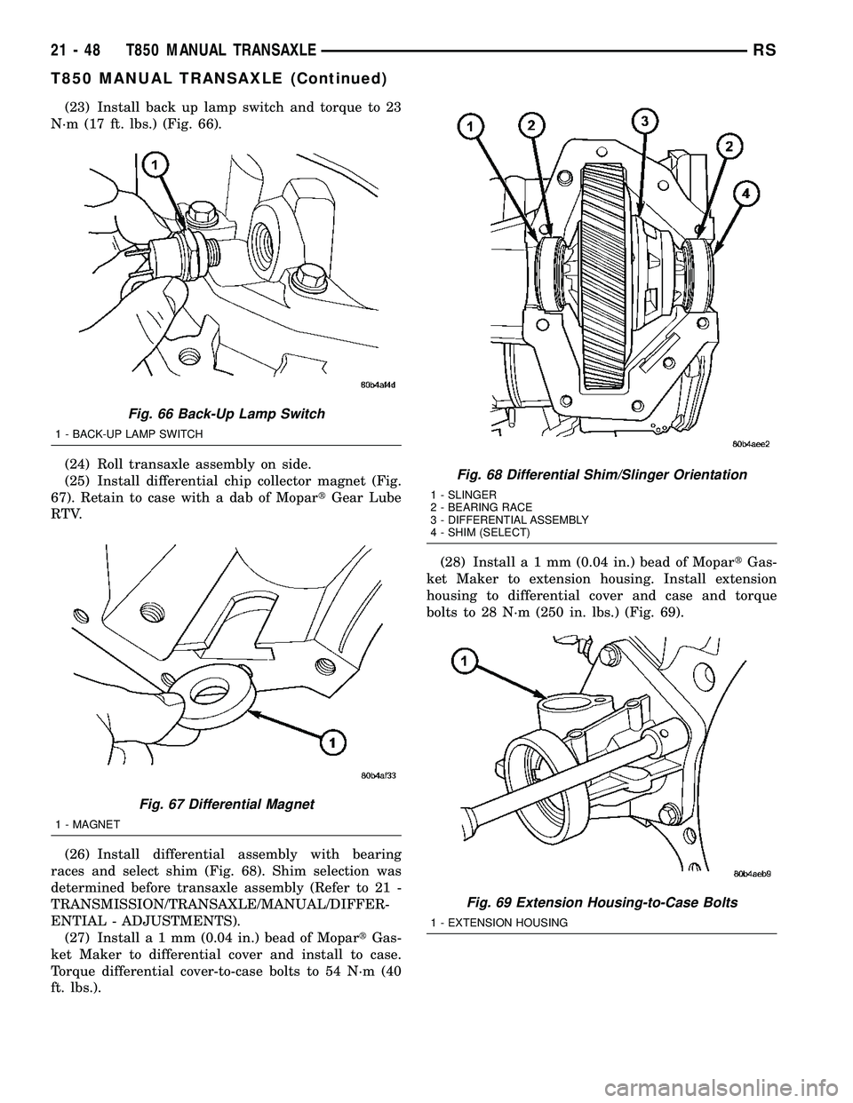
(23) Install back up lamp switch and torque to 23
N´m (17 ft. lbs.) (Fig. 66).
(24) Roll transaxle assembly on side.
(25) Install differential chip collector magnet (Fig.
67). Retain to case with a dab of MopartGear Lube
RTV.
(26) Install differential assembly with bearing
races and select shim (Fig. 68). Shim selection was
determined before transaxle assembly (Refer to 21 -
TRANSMISSION/TRANSAXLE/MANUAL/DIFFER-
ENTIAL - ADJUSTMENTS).
(27) Installa1mm(0.04 in.) bead of MopartGas-
ket Maker to differential cover and install to case.
Torque differential cover-to-case bolts to 54 N´m (40
ft. lbs.).(28) Installa1mm(0.04 in.) bead of MopartGas-
ket Maker to extension housing. Install extension
housing to differential cover and case and torque
bolts to 28 N´m (250 in. lbs.) (Fig. 69).
Fig. 66 Back-Up Lamp Switch
1 - BACK-UP LAMP SWITCH
Fig. 67 Differential Magnet
1 - MAGNET
Fig. 68 Differential Shim/Slinger Orientation
1 - SLINGER
2 - BEARING RACE
3 - DIFFERENTIAL ASSEMBLY
4 - SHIM (SELECT)
Fig. 69 Extension Housing-to-Case Bolts
1 - EXTENSION HOUSING
21 - 48 T850 MANUAL TRANSAXLERS
T850 MANUAL TRANSAXLE (Continued)
Page 1653 of 2585
SPECIFICATIONS - T850 MANUAL TRANSAXLE
GENERAL SPECIFICATIONS
DESCRIPTION SPECIFICATION
Transaxle TypeConstant-mesh, fully synchronized 5-speed with integral
differential
Lubrication MethodSplash oil collected in case passage and oil trough and
distributed to mainshafts via gravity
Fluid Type ATF+4 (Automatic Transmission FluidÐType 9602)
GEAR RATIOS
GEAR RATIO (2.4L Gas) RATIO (2.5L TD)
1st 3.65 3.65
2nd 2.05 2.05
3rd 1.39 1.37
4th 1.03 0.97
5th 0.83 0.76
Reverse 3.47 3.47
Final Drive Ratio 3.77 3.77
Overall Top Gear 3.12 2.67
INPUT SHAFT
BLOCKER RING WEAR GAP
3rd Gear 0.856-1.539 mm (0.0338-0.0606 in.)
4th Gear 0.762-1.631 mm (0.030-0.064 in.)
GEAR END PLAY
3rd Gear 0.099-0.505 mm (0.004-0.020 in.)
4th Gear 0.048-0.457 mm (0.002-0.018 in.)
21 - 56 T850 MANUAL TRANSAXLERS
T850 MANUAL TRANSAXLE (Continued)
Page 1658 of 2585
AXLE SEALS
REMOVAL
(1) Raise vehicle on hoist.
(2) Remove one or both front halfshaft assemblies.
(Refer to 3 - DIFFERENTIAL & DRIVELINE/HALF
SHAFT - REMOVAL)
(3) Using a suitable screwdriver, remove one or
both axle seals (Fig. 92).
INSTALLATION
(1) Using driver handle C-4171 and installer 8476,
install axle seals into position (Fig. 93) (Fig. 94).
(2) Install one or both front halfshaft assemblies.
(Refer to 3 - DIFFERENTIAL & DRIVELINE/HALF
SHAFT - INSTALLATION)
(3) Check transaxle fluid level and adjust if neces-
sary. (Refer to 21 - TRANSMISSION/TRANSAXLE/
MANUAL/FLUID - STANDARD PROCEDURE)
(4) Lower vehicle.
Fig. 92 Axle Seal Removal (Extension Housing Side
Shown)
1 - SCREWDRIVER
2 - AXLE SEAL
3 - EXTENSION HOUSING
Fig. 93 Axle Seal InstallationÐTypical
1 - SEAL
2 - INSTALLER 8476
3 - DRIVER HANDLE C-4171
Fig. 94 Axle Seal Installation (Extension Housing
Side)
1 - EXTENSION HOUSING
2 - SEAL
3 - INSTALLER 8476
4 - DRIVER HANDLE C-4171
RST850 MANUAL TRANSAXLE21-61
Page 1666 of 2585

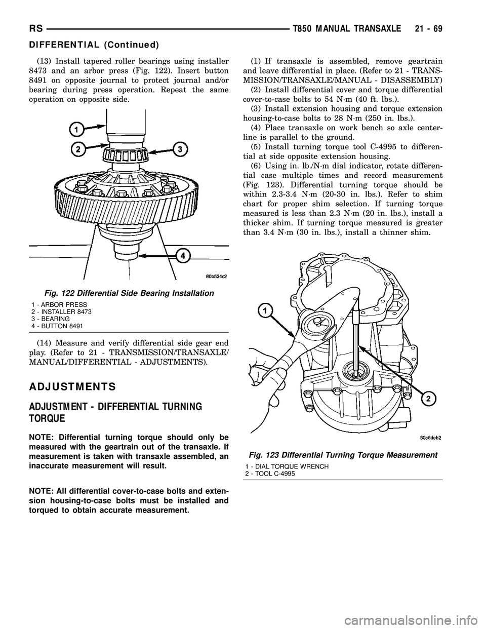
(13) Install tapered roller bearings using installer
8473 and an arbor press (Fig. 122). Insert button
8491 on opposite journal to protect journal and/or
bearing during press operation. Repeat the same
operation on opposite side.
(14) Measure and verify differential side gear end
play. (Refer to 21 - TRANSMISSION/TRANSAXLE/
MANUAL/DIFFERENTIAL - ADJUSTMENTS).
ADJUSTMENTS
ADJUSTMENT - DIFFERENTIAL TURNING
TORQUE
NOTE: Differential turning torque should only be
measured with the geartrain out of the transaxle. If
measurement is taken with transaxle assembled, an
inaccurate measurement will result.
NOTE: All differential cover-to-case bolts and exten-
sion housing-to-case bolts must be installed and
torqued to obtain accurate measurement.(1) If transaxle is assembled, remove geartrain
and leave differential in place. (Refer to 21 - TRANS-
MISSION/TRANSAXLE/MANUAL - DISASSEMBLY)
(2) Install differential cover and torque differential
cover-to-case bolts to 54 N´m (40 ft. lbs.).
(3) Install extension housing and torque extension
housing-to-case bolts to 28 N´m (250 in. lbs.).
(4) Place transaxle on work bench so axle center-
line is parallel to the ground.
(5) Install turning torque tool C-4995 to differen-
tial at side opposite extension housing.
(6) Using in. lb./N´m dial indicator, rotate differen-
tial case multiple times and record measurement
(Fig. 123). Differential turning torque should be
within 2.3-3.4 N´m (20-30 in. lbs.). Refer to shim
chart for proper shim selection. If turning torque
measured is less than 2.3 N´m (20 in. lbs.), install a
thicker shim. If turning torque measured is greater
than 3.4 N´m (30 in. lbs.), install a thinner shim.
Fig. 122 Differential Side Bearing Installation
1 - ARBOR PRESS
2 - INSTALLER 8473
3 - BEARING
4 - BUTTON 8491
Fig. 123 Differential Turning Torque Measurement
1 - DIAL TORQUE WRENCH
2 - TOOL C-4995
RST850 MANUAL TRANSAXLE21-69
DIFFERENTIAL (Continued)