Page 1847 of 2585

VALVE BODY
DESCRIPTION
The valve body assembly consists of a cast alumi-
num valve body, a separator plate, and transfer
plate. The valve body contains valves and check balls
that control fluid delivery to the torque converter
clutch, solenoid/pressure switch assembly, and fric-
tional clutches. The valve body contains the following
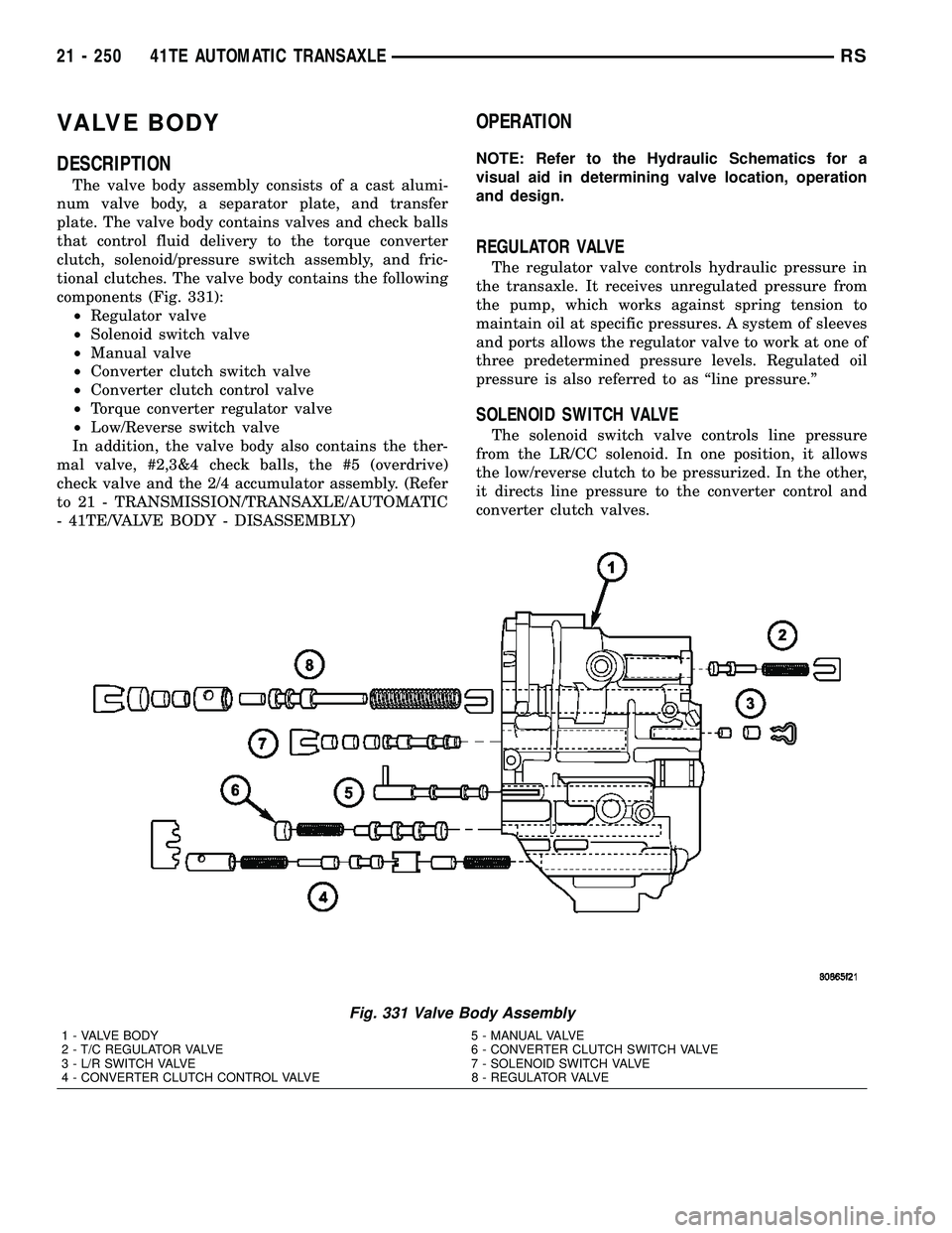
components (Fig. 331):
²Regulator valve
²Solenoid switch valve
²Manual valve
²Converter clutch switch valve
²Converter clutch control valve
²Torque converter regulator valve
²Low/Reverse switch valve
In addition, the valve body also contains the ther-
mal valve, #2,3&4 check balls, the #5 (overdrive)
check valve and the 2/4 accumulator assembly. (Refer
to 21 - TRANSMISSION/TRANSAXLE/AUTOMATIC
- 41TE/VALVE BODY - DISASSEMBLY)
OPERATION
NOTE: Refer to the Hydraulic Schematics for a
visual aid in determining valve location, operation
and design.
REGULATOR VALVE
The regulator valve controls hydraulic pressure in
the transaxle. It receives unregulated pressure from
the pump, which works against spring tension to
maintain oil at specific pressures. A system of sleeves
and ports allows the regulator valve to work at one of
three predetermined pressure levels. Regulated oil
pressure is also referred to as ªline pressure.º
SOLENOID SWITCH VALVE
The solenoid switch valve controls line pressure
from the LR/CC solenoid. In one position, it allows
the low/reverse clutch to be pressurized. In the other,
it directs line pressure to the converter control and
converter clutch valves.
Fig. 331 Valve Body Assembly
1 - VALVE BODY 5 - MANUAL VALVE
2 - T/C REGULATOR VALVE 6 - CONVERTER CLUTCH SWITCH VALVE
3 - L/R SWITCH VALVE 7 - SOLENOID SWITCH VALVE
4 - CONVERTER CLUTCH CONTROL VALVE 8 - REGULATOR VALVE
21 - 250 41TE AUTOMATIC TRANSAXLERS
Page 1848 of 2585

MANUAL VALVE
The manual valve is operated by the mechanical
shift linkage. Its primary responsibility is to send
line pressure to the appropriate hydraulic circuits
and solenoids. The valve has three operating ranges
or positions.
CONVERTER CLUTCH SWITCH VALVE
The main responsibility of the converter clutch
switch valve is to control hydraulic pressure applied
to the front (off) side of the converter clutch piston.
Line pressure from the regulator valve is fed to the
torque converter regulator valve, where it passes
through the valve, and is slightly regulated. The
pressure is then directed to the converter clutch
switch valve and to the front side of the converter
clutch piston. This pressure pushes the piston back
and disengages the converter clutch.
CONVERTER CLUTCH CONTROL VALVE
The converter clutch control valve controls the
back (on) side of the torque converter clutch. When
the PCM/TCM energizes or modulates the LR/CC
solenoid to apply the converter clutch piston, both
the converter clutch control valve and the converter
control valve move, allowing pressure to be applied to
the back side of the clutch.
T/C REGULATOR VALVE
The torque converter regulator valve slightly regu-
lates the flow of fluid to the torque converter.
LOW/REVERSE SWITCH VALVE
The low/reverse clutch is applied from different
sources, depending on whether low (1st) gear or
reverse is selected. The low/reverse switch valve
alternates positions depending on from which direc-
tion fluid pressure is applied. By design, when the
valve is shifted by fluid pressure from one channel,
the opposing channel is blocked. The switch valve
alienates the possibility of a sticking ball check, thus
providing consistent application of the low/reverse
clutch under all operating conditions.
REMOVAL
NOTE: If valve body is replaced or reconditioned,
the TCM Quick Learn Procedure must be per-
formed. (Refer to 8 - ELECTRICAL/ELECTRONIC
CONTROL MODULES/TRANSMISSION CONTROL
MODULE - STANDARD PROCEDURE)(1) Disconnect battery negative cable.
(2) Disconnect gearshift cable from manual valve
lever.
(3) Remove manual valve lever from manual shaft.
(4) Raise vehicle on hoist.
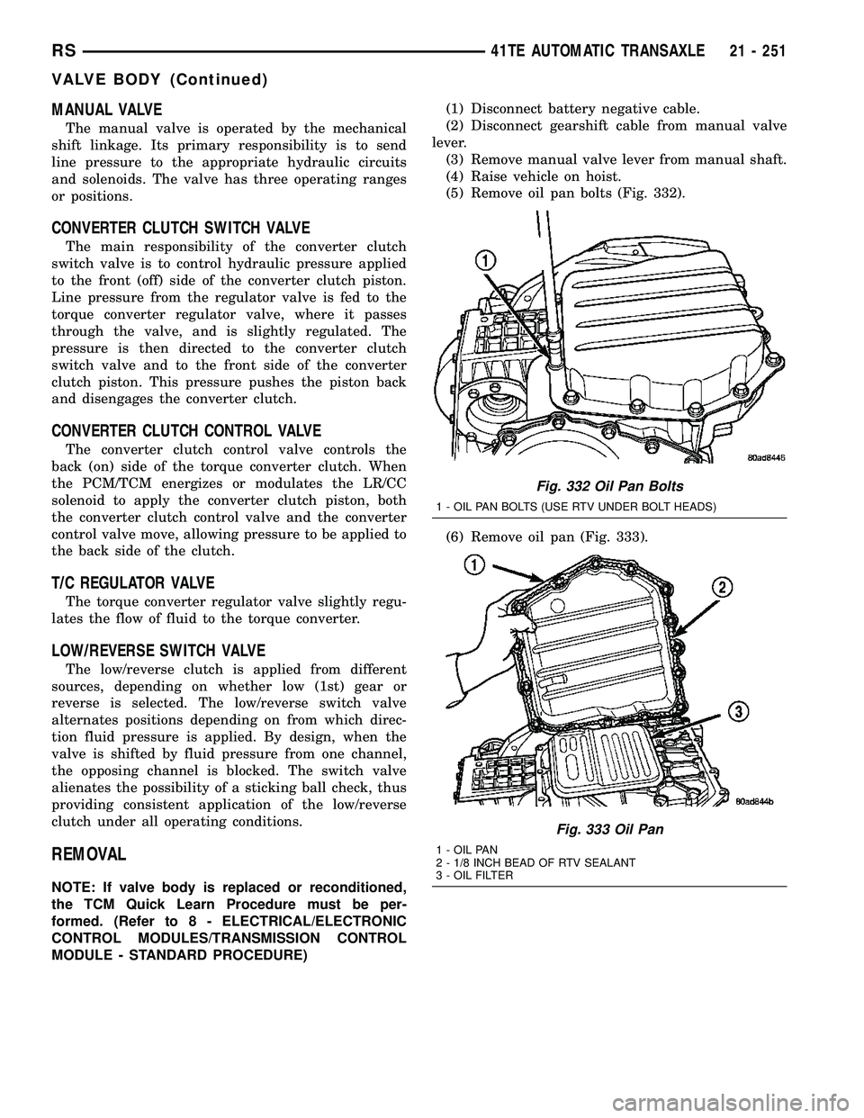
(5) Remove oil pan bolts (Fig. 332).
(6) Remove oil pan (Fig. 333).
Fig. 332 Oil Pan Bolts
1 - OIL PAN BOLTS (USE RTV UNDER BOLT HEADS)
Fig. 333 Oil Pan
1 - OIL PAN
2 - 1/8 INCH BEAD OF RTV SEALANT
3 - OIL FILTER
RS41TE AUTOMATIC TRANSAXLE21 - 251
VALVE BODY (Continued)
Page 1849 of 2585

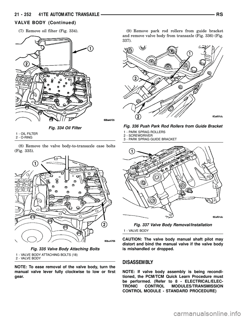
(7) Remove oil filter (Fig. 334).
(8) Remove the valve body-to-transaxle case bolts
(Fig. 335).
NOTE: To ease removal of the valve body, turn the
manual valve lever fully clockwise to low or first
gear.(9) Remove park rod rollers from guide bracket
and remove valve body from transaxle (Fig. 336) (Fig.
337).
CAUTION: The valve body manual shaft pilot may
distort and bind the manual valve if the valve body
is mishandled or dropped.
DISASSEMBLY
NOTE: If valve body assembly is being recondi-
tioned, the PCM/TCM Quick Learn Procedure must
be performed. (Refer to 8 - ELECTRICAL/ELEC-
TRONIC CONTROL MODULES/TRANSMISSION
CONTROL MODULE - STANDARD PROCEDURE)
Fig. 334 Oil Filter
1 - OIL FILTER
2 - O-RING
Fig. 335 Valve Body Attaching Bolts
1 - VALVE BODY ATTACHING BOLTS (18)
2 - VALVE BODY
Fig. 336 Push Park Rod Rollers from Guide Bracket
1 - PARK SPRAG ROLLERS
2 - SCREWDRIVER
3 - PARK SPRAG GUIDE BRACKET
Fig. 337 Valve Body Removal/Installation
1 - VALVE BODY
21 - 252 41TE AUTOMATIC TRANSAXLERS
VALVE BODY (Continued)
Page 1850 of 2585
(1) Remove manual shaft seal (Fig. 338).
(2) Remove Transmission Range Sensor retaining
screw (Fig. 339).(3) Remove Manual Shaft/Rooster Comb and
Transmission Range Sensor (Fig. 340).
(4) Remove 2/4 Accumulator Retaining Plate (Fig.
341).
Fig. 338 Manual Shaft Seal
1 - SEAL
2 - MANUAL SHAFT
Fig. 339 Remove Transmission Range Sensor
1 - TRANSMISSION RANGE SENSOR
2 - MANUAL VALVE CONTROL PIN
3 - RETAINING SCREW
Fig. 340 Manual Shaft/Rooster Comb and
Transmission Range Sensor
1 - TRANSMISSION RANGE SENSOR
2 - MANUAL SHAFT
3 - ROOSTER COMB
Fig. 341 2/4 Accumulator Retaining Plate
1 - 2±4 ACCUMULATOR RETAINING PLATE
2 - DETENT SPRING
RS41TE AUTOMATIC TRANSAXLE21 - 253
VALVE BODY (Continued)
Page 1854 of 2585
(15) Remove remaining retainers as shown in (Fig.
352).(16) Remove valves and springs as shown in (Fig.
353).
NOTE: Refer to Valve Body Cleaning and Inspection
for cleaning procedures.
ASSEMBLY
NOTE: If valve body assembly is reconditioned, the
PCM/TCM Quick Learn Procedure must be per-
formed. (Refer to 8 - ELECTRICAL/ELECTRONIC
CONTROL MODULES/TRANSMISSION CONTROL
MODULE - STANDARD PROCEDURE)
(1) Install valves and springs as shown in (Fig.
353).
Fig. 353 Springs and Valves Location
1 - VALVE BODY 5 - MANUAL VALVE
2 - T/C REGULATOR VALVE 6 - CONVERTER CLUTCH SWITCH VALVE
3 - L/R SWITCH VALVE 7 - SOLENOID SWITCH VALVE
4 - CONVERTER CLUTCH CONTROL VALVE 8 - REGULATOR VALVE
Fig. 352 Valve Retainer Location
1 - RETAINER
2 - RETAINER
RS41TE AUTOMATIC TRANSAXLE21 - 257
VALVE BODY (Continued)
Page 1858 of 2585
(12) Install 2/4 Accumulator components as shown
in (Fig. 364).
(13) Torque 2/4 Accumulator retainer to 5 N´m (45
in. lbs.) (Fig. 365).(14) Install Manual Shaft/Rooster Comb and
Transmission Range Sensor (Fig. 366).
(15) Make sure Manual Valve control pin is con-
tained within the rooster comb slot (Fig. 367). Install
Transmission Range Sensor retaining screw (Fig.
367) and torque to 5 N´m (45 in. lbs.).
Fig. 364 2/4 Accumulator Assembly
1 - VALVE BODY
2 - RETAINER PLATE
3 - DETENT SPRING
4 - SPRINGS
5 - SEALS
6 - PISTON
Fig. 365 2/4 Accumulator Retaining Plate
1 - 2±4 ACCUMULATOR RETAINING PLATE
2 - DETENT SPRING
Fig. 366 Install Manual Shaft/Rooster Comb and
Transmission Range Sensor
1 - TRANSMISSION RANGE SENSOR
2 - MANUAL SHAFT
3 - ROOSTER COMB
Fig. 367 Install Transmission Range Sensor
Retaining Screw
1 - TRANSMISSION RANGE SENSOR
2 - MANUAL VALVE CONTROL PIN
3 - RETAINING SCREW
RS41TE AUTOMATIC TRANSAXLE21 - 261
VALVE BODY (Continued)
Page 1859 of 2585
(16) Install manual shaft seal (Fig. 368).
INSTALLATION
NOTE: If valve body assembly is being replaced or
reconditioned, it is necessary to perform the TCM
Quick Learn Procedure. (Refer to 8 - ELECTRICAL/
ELECTRONIC CONTROL MODULES/TRANSMISSION
CONTROL MODULE - STANDARD PROCEDURE)
(1) Install valve body assembly to transaxle (Fig.
369). Install and torque valve body-to-transaxle case
bolts (Fig. 370) to 12 N´m (105 in. lbs.).(2) Install transaxle oil filter (Fig. 371). Inspect
the o-ring and replace if necessary.
Fig. 368 Manual Shaft Seal
1 - SEAL
2 - MANUAL SHAFT
Fig. 369 Valve Body Removal/Installation
1 - VALVE BODY
Fig. 370 Valve Body Attaching Bolts
1 - VALVE BODY ATTACHING BOLTS (18)
2 - VALVE BODY
Fig. 371 Oil Filter
1 - OIL FILTER
2 - O-RING
21 - 262 41TE AUTOMATIC TRANSAXLERS
VALVE BODY (Continued)
Page 1860 of 2585
(3) Ensure the transaxle oil pan and transaxle
case sealing surfaces are clean and dry. Install an
1/8º bead of MopartSilicone Rubber Adhesive Seal-
ant to the oil pan and install (Fig. 372). Torque oil
pan-to-transaxle case bolts (Fig. 373) to 19 N´m (165
in. lbs.).
(4) Lower vehicle.
(5) Connect transmission range sensor connector.(6) Install manual valve lever to manual shaft.
(7) Install gearshift cable to manual valve lever.
(8) Connect battery negative cable.
(9) Fill transaxle with MopartATF +4 Transmis-
sion fluid. (Refer to 21 - TRANSMISSION/TRANS-
AXLE/AUTOMATIC - 41TE/FLUID - STANDARD
PROCEDURE)
Fig. 372 Oil Pan
1 - OIL PAN
2 - 1/8 INCH BEAD OF RTV SEALANT
3 - OIL FILTER
Fig. 373 Oil Pan Bolts
1 - OIL PAN BOLTS (USE RTV UNDER BOLT HEADS)
RS41TE AUTOMATIC TRANSAXLE21 - 263
VALVE BODY (Continued)