2004 CHRYSLER VOYAGER fuel cap release
[x] Cancel search: fuel cap releasePage 592 of 2585

Body Diagnostic Manual for a complete list of diag-
nostic routines.
NOTE: It may be possible to generate Sliding Door
Diagnostic Trouble Codes during normal power
sliding door operation. Refer to the Body Diagnos-
tic Manual for a complete list of diagnostic routines.
For additional information, (Refer to 8 - ELECTRI-
CAL/POWER DOORS - OPERATION). For a com-
plete power sliding door system wiring schematic,
refer to Wiring Diagrams. For power sliding door sys-
tem operation instructions, refer to the vehicle owner
manual.
WARNING: BE CERTAIN TO READ ALL WARNINGS
AND CAUTIONS IN POWER SLIDING DOOR OPER-
ATION BEFORE ATTEMPTING ANY SERVICE OF
POWER SLIDING DOOR SYSTEM OR COMPO-
NENTS.
OPERATION
With the push of a power sliding door open/close
command switch (key fob, overhead console or B-pil-
lar mounted) a signal is sent out to the Body Control
Module (BCM). The BCM then sends a signal out on
the PCI Data Bus circuit (J1850) to the power sliding
door module. The power sliding door module then
signals the power sliding door latch to release the
door to the unlatched and movable position. The
motor then starts an open cycle.
During the door open cycle, if the power sliding
door module detects sufficient resistance to doortravel, such as an obstruction in the door's path, the
power sliding door module will immediately stop door
movement and reverse door travel to the full open or
closed position. The ability for the power sliding door
module to detect resistance to door travel is accom-
plished by hall effect sensors and the door motor
speed.
The power sliding door control module has the abil-
ity to learn. Anytime a door is opened or closed using
the power sliding door system the module learns
from its cycle. If a replacement power sliding door
component is installed or a door adjustment is made,
the module must re-learn the effort required to open
or close the door. A learn cycle can be performed with
a Diagnostic Scan Tool, such as the DRB IIIt, or with
a complete cycle of the door, using any one of the
command switches. Refer to Standard Procedures in
this section for detailed instructions.
The power sliding door system is designed with a
number of system inhibitors. These inhibitors are
necessary for safety and/or feasibility of the power
sliding door system. See the power sliding door sys-
tem inhibitors noted below:
POWER SLIDING DOOR SYSTEM INHIBITORS
²The power sliding door must be in thefullopen
or closed position in order for the power sliding door
system to start a cycle. If the door is not in this posi-
tion (based on the input from the full open, pawl or
ratchet switches) the door control module will not
respond to command switch inputs.
²The vehicles transmission must be inpark or
neutralin order for the power sliding door system to
start a cycle.
²The vehicles child lockout switch must be in the
ªUNLOCKEDº position in order for the power sliding
door systems B-pillar switches to function.
²If multiple obstacles are detected during the
same power open or close cycle the power sliding
door may go into full manual mode.
²If severe Diagnostic Trouble Codes (DTC) are
stored in the power sliding door control module the
power sliding door may go into full manual mode.
²Due to the high pressure created in the passen-
ger compartment with the blower motor on high, the
power sliding door may not complete a power close
cycle unless a window is cracked, allowing the pres-
sure to escape. This situation will only be experi-
enced on some vehicles, or vehicles with brand new
side door weather seals installed. Refer to the Side
Door Adjustment procedure in the Standard Proce-
dures section of this group.
²The vehicles fuel tank filler door must be in the
closed position. Due to the sliding door interference
with the open fuel tank filler door, mechanical link-
age prevents the side door from opening and striking
Fig. 3 Power Side Door Fuse Location
RSPOWER SLIDING DOOR SYSTEM8N-21
POWER SLIDING DOOR SYSTEM (Continued)
Page 1322 of 2585
²Excessive steam (white smoke) emitting from
exhaust
²Coolant foaming
CYLINDER-TO-CYLINDER LEAKAGE TEST
To determine if an engine cylinder head gasket is
leaking between adjacent cylinders, follow the proce-
dures in Cylinder Compression Pressure Test (Refer
to 9 - ENGINE - DIAGNOSIS AND TESTING). An
engine cylinder head gasket leaking between adja-
cent cylinders will result in approximately a 50±70%
reduction in compression pressure.
CYLINDER-TO-WATER JACKET LEAKAGE TEST
WARNING: USE EXTREME CAUTION WHEN THE
ENGINE IS OPERATING WITH COOLANT PRES-
SURE CAP REMOVED.
VISUAL TEST METHOD
With the engine cool, remove the coolant pressure
cap. Start the engine and allow it to warm up until
thermostat opens.
If a large combustion/compression pressure leak
exists, bubbles will be visible in the coolant.COOLING SYSTEM TESTER METHOD
WARNING: WITH COOLING SYSTEM TESTER IN
PLACE, PRESSURE WILL BUILD UP FAST. EXCES-
SIVE PRESSURE BUILT UP, BY CONTINUOUS
ENGINE OPERATION, MUST BE RELEASED TO A
SAFE PRESSURE POINT. NEVER PERMIT PRES-
SURE TO EXCEED 138 kPa (20 psi).
Install Cooling System Tester 7700 or equivalent to
pressure cap neck. Start the engine and observe the
tester's pressure gauge. If gauge pulsates with every
power stroke of a cylinder a combustion pressure
leak is evident.
CHEMICAL TEST METHOD
Combustion leaks into the cooling system can also
be checked by using Bloc-Chek Kit C-3685-A or
equivalent. Perform test following the procedures
supplied with the tool kit.
REMOVAL - CYLINDER HEAD
(1) Perform fuel system pressure release procedure
before attempting any repairs.(Refer to 14 -
FUEL SYSTEM/FUEL DELIVERY - SPECIFICA-
TIONS)
(2) Disconnect battery negative cable.
(3) Drain cooling system. (Refer to 7 - COOLING -
STANDARD PROCEDURE)
(4) Remove air filter housing and inlet tube.
(5) Remove upper intake manifold. (Refer to 9 -
ENGINE/MANIFOLDS/INTAKE MANIFOLD -
REMOVAL)
(6) Remove heater tube support bracket from cyl-
inder head.
(7) Disconnect radiator upper and heater supply
hoses from intake manifold water outlet connections.
(8) Remove accessory drive belts. (Refer to 7 -
COOLING/ACCESSORY DRIVE/DRIVE BELTS -
REMOVAL)
(9) Raise vehicle and remove exhaust pipe from
manifold.
(10) Remove power steering pump reservoir and
line support bracket from lower intake manifold and
set aside. Do not disconnect lines.
(11) Remove ignition coil and wires from engine.
(12) Disconnect cam sensor and fuel injector wir-
ing connectors.
(13) Remove timing belt and camshaft sprockets.
(Refer to 9 - ENGINE/VALVE TIMING/TIMING
BELT/CHAIN AND SPROCKETS - REMOVAL)
(14) Remove timing belt idler pulley and rear tim-
ing belt cover. (Refer to 9 - ENGINE/VALVE TIM-
ING/TIMING BELT / CHAIN COVER(S) -
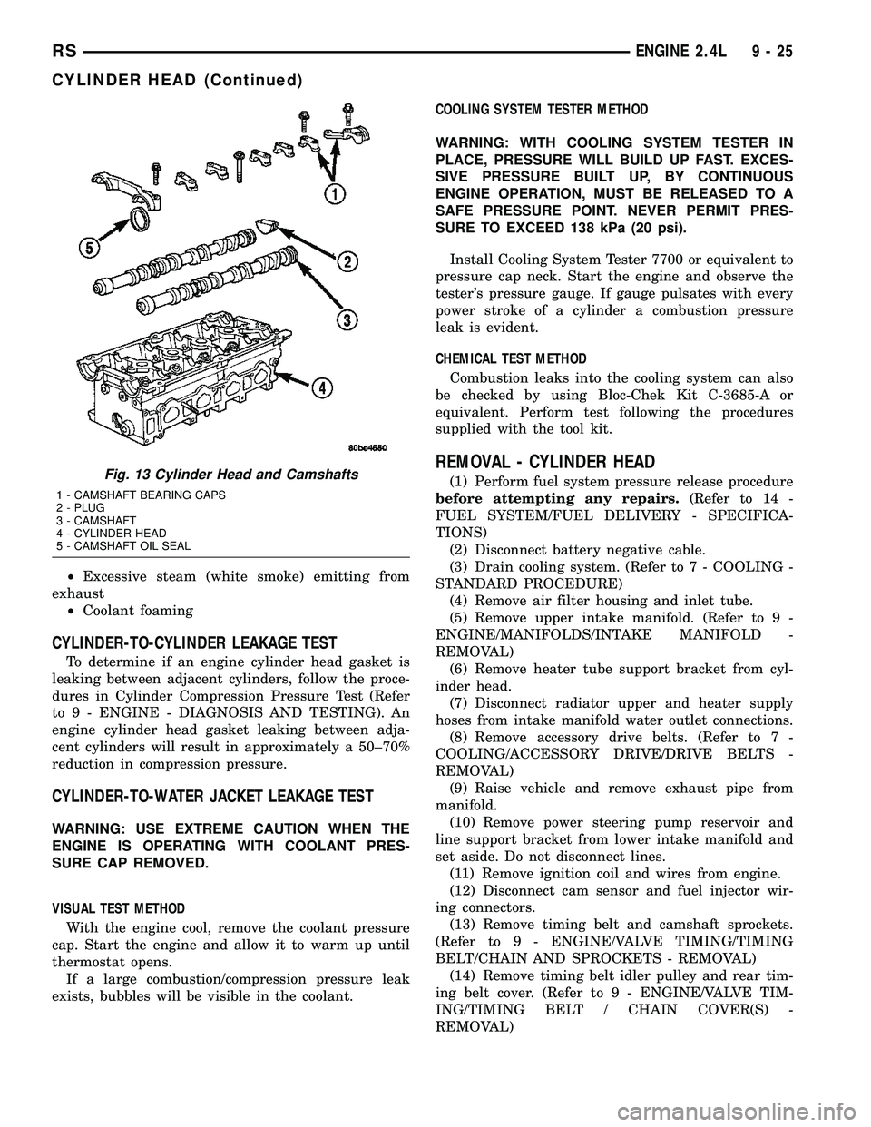
REMOVAL)Fig. 13 Cylinder Head and Camshafts
1 - CAMSHAFT BEARING CAPS
2 - PLUG
3 - CAMSHAFT
4 - CYLINDER HEAD
5 - CAMSHAFT OIL SEAL
RSENGINE 2.4L9-25
CYLINDER HEAD (Continued)
Page 1383 of 2585
(1) Inspect air cleaner, induction system and
intake manifold to insure system is dry and clear of
foreign material.
(2) Remove negative battery cable.
(3) Place a shop towel around the spark plugs
when removing them from the engine. This will catch
any fluid that may possibly be in the cylinder under
pressure.
(4) With all spark plugs removed, rotate engine
crankshaft using a breaker bar and socket.
(5) Identify the fluid in the cylinder(s) (i.e., cool-
ant, fuel, oil or other).
(6) Make sure all fluid has been removed from the
cylinders. Inspect engine for damage (i.e., connecting
rods, pistons, valves, etc.)
(7) Repair engine or components as necessary to
prevent this problem from re-occurring.
CAUTION: Squirt approximately one teaspoon of oil
into the cylinders, rotate engine to lubricate the cyl-
inder walls to prevent damage on restart.
(8) Install new spark plugs.
(9) Drain engine oil and remove oil filter.
(10) Install a new oil filter.
(11) Fill engine with specified amount of approved
oil.
(12) Connect negative battery cable.
(13) Start engine and check for any leaks.
STANDARD PROCEDURE - REPAIR OF
DAMAGED OR WORN THREADS
Damaged or worn threads (excluding spark plug
and camshaft bearing cap attaching threads) can be
repaired. Essentially, this repair consists of drilling
out worn or damaged threads, tapping the hole with
a special Heli-Coil Tap, (or equivalent) and installing
an insert into the tapped hole. This brings the hole
back to its original thread size.
CAUTION: Be sure that the tapped holes maintain
the original center line.
Heli-Coil tools and inserts are readily available
from automotive parts jobbers.
STANDARD PROCEDURE - ENGINE CORE AND
OIL GALLERY PLUGS
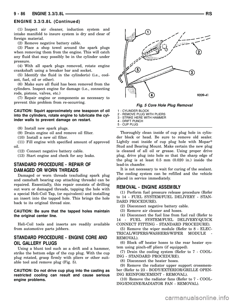
Using a blunt tool such as a drift and a hammer,
strike the bottom edge of the cup plug. With the cup
plug rotated, grasp firmly with pliers or other suit-
able tool and remove plug (Fig. 5).
CAUTION: Do not drive cup plug into the casting as
restricted cooling can result and cause serious
engine problems.Thoroughly clean inside of cup plug hole in cylin-
der block or head. Be sure to remove old sealer.
Lightly coat inside of cup plug hole with Mopart
Stud and Bearing Mount. Make certain the new plug
is cleaned of all oil or grease. Using proper drive
plug, drive plug into hole so that the sharp edge of
the plug is at least 0.5 mm (0.020 in.) inside the
lead-in chamfer.
It is not necessary to wait for curing of the sealant.
The cooling system can be refilled and the vehicle
placed in service immediately.
REMOVAL - ENGINE ASSEMBLY
(1) Perform fuel pressure release procedure (Refer
to 14 - FUEL SYSTEM/FUEL DELIVERY - STAN-
DARD PROCEDURE).
(2) Disconnect negative battery cable.
(3) Remove air cleaner and hoses.
(4) Disconnect the fuel line from fuel rail (Refer to
14 - FUEL SYSTEM/FUEL DELIVERY/QUICK
CONNECT FITTING - STANDARD PROCEDURE).
(5) Remove the wiper module (Refer to 8 - ELEC-
TRICAL/WIPERS/WASHERS/WIPER MODULE -
REMOVAL).
(6) Block off heater hoses to the rear heater sys-
tem using pinch-off pliers (if equipped).
(7) Drain the cooling system (Refer to 7 - COOL-
ING - STANDARD PROCEDURE).
(8) Disconnect the heater hoses.
(9) Remove the radiator upper support crossmem-
ber (Refer to 23 - BODY/EXTERIOR/GRILLE OPEN-
ING REINFORCEMENT - REMOVAL).
(10) Remove the radiator fans (Refer to 7 - COOL-
ING/ENGINE/RADIATOR FAN - REMOVAL).
Fig. 5 Core Hole Plug Removal
1 - CYLINDER BLOCK
2 - REMOVE PLUG WITH PLIERS
3 - STRIKE HERE WITH HAMMER
4 - DRIFT PUNCH
5 - CUP PLUG
9 - 86 ENGINE 3.3/3.8LRS
ENGINE 3.3/3.8L (Continued)
Page 1396 of 2585
AIR CLEANER HOUSING
REMOVAL
(1) Disconnect the negative battery cable.
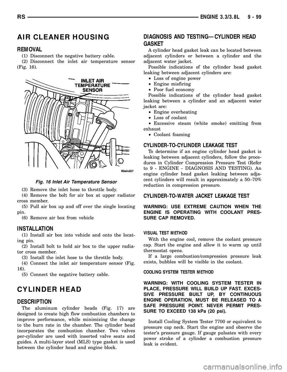
(2) Disconnect the inlet air temperature sensor
(Fig. 16).
(3) Remove the inlet hose to throttle body.
(4) Remove the bolt for air box at upper radiator
cross member.
(5) Pull air box up and off over the single locating
pin.
(6) Remove air box from vehicle
INSTALLATION
(1) Install air box into vehicle and onto the locat-
ing pin.
(2) Install bolt to hold air box to the upper radia-
tor cross member.
(3) Install the inlet hose to the throttle body.
(4) Connect the inlet air temperature sensor (Fig.
16).
(5) Connect the negative battery cable.
CYLINDER HEAD
DESCRIPTION
The aluminum cylinder heads (Fig. 17) are
designed to create high flow combustion chambers to
improve performance, while minimizing the change
to the burn rate in the chamber. The cylinder head
incorporates the combustion chamber. Two valves
per-cylinder are used with inserted valve seats and
guides. A multi-layer steel (MLS) type gasket is used
between the cylinder head and engine block.
DIAGNOSIS AND TESTINGÐCYLINDER HEAD
GASKET
A cylinder head gasket leak can be located between
adjacent cylinders or between a cylinder and the
adjacent water jacket.
Possible indications of the cylinder head gasket
leaking between adjacent cylinders are:
²Loss of engine power
²Engine misfiring
²Poor fuel economy
Possible indications of the cylinder head gasket
leaking between a cylinder and an adjacent water
jacket are:
²Engine overheating
²Loss of coolant
²Excessive steam (white smoke) emitting from
exhaust
²Coolant foaming
CYLINDER-TO-CYLINDER LEAKAGE TEST
To determine if an engine cylinder head gasket is
leaking between adjacent cylinders, follow the proce-
dures in Cylinder Compression Pressure Test (Refer
to 9 - ENGINE - DIAGNOSIS AND TESTING). An
engine cylinder head gasket leaking between adja-
cent cylinders will result in approximately a 50±70%
reduction in compression pressure.
CYLINDER-TO-WATER JACKET LEAKAGE TEST
WARNING: USE EXTREME CAUTION WHEN THE
ENGINE IS OPERATING WITH COOLANT PRES-
SURE CAP REMOVED.
VISUAL TEST METHOD
With the engine cool, remove the coolant pressure
cap. Start the engine and allow it to warm up until
thermostat opens.
If a large combustion/compression pressure leak
exists, bubbles will be visible in the coolant.
COOLING SYSTEM TESTER METHOD
WARNING: WITH COOLING SYSTEM TESTER IN
PLACE, PRESSURE WILL BUILD UP FAST. EXCES-
SIVE PRESSURE BUILT UP, BY CONTINUOUS
ENGINE OPERATION, MUST BE RELEASED TO A
SAFE PRESSURE POINT. NEVER PERMIT PRES-
SURE TO EXCEED 138 kPa (20 psi).
Install Cooling System Tester 7700 or equivalent to
pressure cap neck. Start the engine and observe the
tester's pressure gauge. If gauge pulsates with every
power stroke of a cylinder a combustion pressure
leak is evident.
Fig. 16 Inlet Air Temperature Sensor
RSENGINE 3.3/3.8L9-99
Page 1489 of 2585
SPECIAL TOOLS
EXHAUST SYSTEM
CATALYTIC CONVERTER
DESCRIPTION
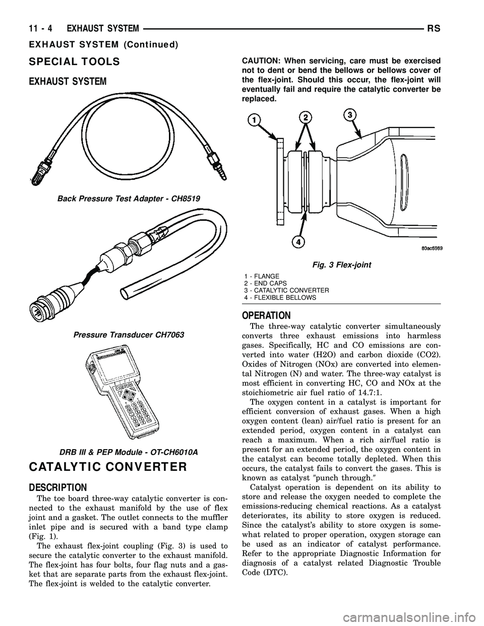
The toe board three-way catalytic converter is con-
nected to the exhaust manifold by the use of flex
joint and a gasket. The outlet connects to the muffler
inlet pipe and is secured with a band type clamp
(Fig. 1).
The exhaust flex-joint coupling (Fig. 3) is used to
secure the catalytic converter to the exhaust manifold.
The flex-joint has four bolts, four flag nuts and a gas-
ket that are separate parts from the exhaust flex-joint.
The flex-joint is welded to the catalytic converter.
CAUTION: When servicing, care must be exercised
not to dent or bend the bellows or bellows cover of
the flex-joint. Should this occur, the flex-joint will
eventually fail and require the catalytic converter be
replaced.
OPERATION
The three-way catalytic converter simultaneously
converts three exhaust emissions into harmless
gases. Specifically, HC and CO emissions are con-
verted into water (H2O) and carbon dioxide (CO2).
Oxides of Nitrogen (NOx) are converted into elemen-
tal Nitrogen (N) and water. The three-way catalyst is
most efficient in converting HC, CO and NOx at the
stoichiometric air fuel ratio of 14.7:1.
The oxygen content in a catalyst is important for
efficient conversion of exhaust gases. When a high
oxygen content (lean) air/fuel ratio is present for an
extended period, oxygen content in a catalyst can
reach a maximum. When a rich air/fuel ratio is
present for an extended period, the oxygen content in
the catalyst can become totally depleted. When this
occurs, the catalyst fails to convert the gases. This is
known as catalyst9punch through.9
Catalyst operation is dependent on its ability to
store and release the oxygen needed to complete the
emissions-reducing chemical reactions. As a catalyst
deteriorates, its ability to store oxygen is reduced.
Since the catalyst's ability to store oxygen is some-
what related to proper operation, oxygen storage can
be used as an indicator of catalyst performance.
Refer to the appropriate Diagnostic Information for
diagnosis of a catalyst related Diagnostic Trouble
Code (DTC).
Back Pressure Test Adapter - CH8519
Pressure Transducer CH7063
DRB III & PEP Module - OT-CH6010A
Fig. 3 Flex-joint
1 - FLANGE
2 - END CAPS
3 - CATALYTIC CONVERTER
4 - FLEXIBLE BELLOWS
11 - 4 EXHAUST SYSTEMRS
EXHAUST SYSTEM (Continued)
Page 1509 of 2585
FUEL DELIVERY
DESCRIPTION
The front wheel drive car uses a plastic fuel tank
located rear center of the vehicle.
The Fuel Delivery System consists of: the following
items:
²Electric fuel pump module
²Fuel filter
²Tubes/lines/hoses
²Fuel injectors
The in-tank fuel pump module contains the fuel
pump. The pump is serviced as part of the fuel pump
module. Refer to Fuel Pump Module.
The fuel filter is replaceable only as part of the
fuel pump module.
OPERATION
The fuel system provides fuel pressure by an
in-tank pump module. The Powertrain Control Mod-
ule (PCM) controls the operation of the fuel system
by providing battery voltage to the fuel pump
through the fuel pump relay. The PCM requires only
three inputs and a good ground to operate the fuel
pump relay. The three inputs are:
²Ignition voltage
²Crankshaft Position (CKP) sensor
²Camshaft Position (CMP) sensor
DIAGNOSIS AND TESTING - FUEL DELIVERY
SYSTEM
(Refer to Appropriate Diagnostic Information)
STANDARD PROCEDURE
STANDARD PROCEDURE - FUEL SYSTEM
PRESSURE RELEASE PROCEDURE
(1) Remove Fuel Pump relay from Power Distribu-
tion Center (PDC). For location of relay, refer to label
on underside of PDC cover.
(2) Start and run engine until it stalls.
(3) Attempt restarting engine until it will no
longer run.
(4) Turn ignition key to OFF position.
(5) Return fuel pump relay to PDC.
(6) One or more Diagnostic Trouble Codes (DTC's)
may have been stored in PCM memory due to fuel
pump relay removal. The DRB IIItscan tool must be
used to erase a DTC.
STANDARD PROCEDURE - DRAINING FUEL
TANK
Two different procedures may be used to drain fuel
tank (lowering tank or using DRBIIItscan tool).The quickest draining procedure involves lowering
the fuel tank.
WARNING: RELEASE FUEL SYSTEM PRESSURE
BEFORE SERVICING FUEL SYSTEM COMPONENTS.
SERVICE VEHICLES IN WELL VENTILATED AREAS
AND AVOID IGNITION SOURCES. NEVER SMOKE
WHILE SERVICING THE VEHICLE. THIS MAY
RESULT IN PERSONAL INJURY OR DEATH.
As an alternative procedure, the electric fuel pump
may be activated allowing tank to be drained at fuel
rail connection. Refer to DRBIIItscan tool for fuel
pump activation procedures. Before disconnecting
fuel line at fuel rail, release fuel pressure. Refer to
the Fuel System Pressure Release Procedure in this
group for procedures. Disconnect the fuel line at the
fuel rail and remove the plastic retainer from the
fuel rail. Take plastic retainer and install it back into
the fuel line from body. Check the O-ring and make
sure that it is in place and not damaged. Attach end
of special test hose tool number 6539 at fuel line con-
nection from the body line. Position opposite end of
this hose tool to an approved gasoline draining sta-
tion. Activate fuel pump and drain tank until empty.
When done remove the special test hose tool number
6539 from the body line. Remove the plastic retainer
from the special test hose tool number 6539 and rein-
stall it into the fuel line from the body. Check the
O-ring and make sure that it is in place and not
damaged. Install the fuel line to the fuel rail.
If electric fuel pump is not operating, tank must be
lowered for fuel draining. Refer to following proce-
dures.
(1) Remove fuel filler cap.
(2) Perform the Fuel System Pressure Release pro-
cedure.
(3) Disconnect negative cable from battery.
(4) Raise vehicle and support.
(5) Certain models are equipped with a separate
grounding wire (strap) connecting the fuel fill tube
assembly to the body. Disconnect wire by removing
screw.
(6) Open fuel fill door and remove screws mount-
ing fuel filler tube assembly to body. Do not discon-
nect rubber fuel fill or vent hoses from tank at this
time.
(7) Place a transmission jack under center of fuel
tank. Apply a slight amount of pressure to fuel tank
with transmission jack.
(8) Remove fuel tank mounting straps.
(9)Lower the tank just enough so that the
filler tube fitting is the highest point of the fuel
tank.
(10) Remove filler tube from fuel tank. Tank will
be drained through this fitting.
14 - 2 FUEL DELIVERYRS
Page 1515 of 2585
FUEL PUMP
DESCRIPTION
The electric fuel pump is located in and is part of
the fuel pump module. It is a positive displacement,
gerotor type, immersible pump with a permanent
magnet electric motor. The fuel pump module is sus-
pended in fuel in the fuel tank.
OPERATION
The pump draws fuel through a strainer and
pushes it through the motor to the outlet. The pump
contains a check valve. The valve, in the pump out-
let, maintains pump pressure during engine off con-
ditions, for a short while. It is normal for fuel
pressure to drop to zero after cooldown. The fuel
pump relay provides voltage to the fuel pump. The
fuel pump has a maximum deadheaded pressure out-
put of approximately 880 kPa (130 psi). The regula-
tor adjusts fuel system pressure to approximately
400 kpa 34 kpa (58 psi 5 psi).
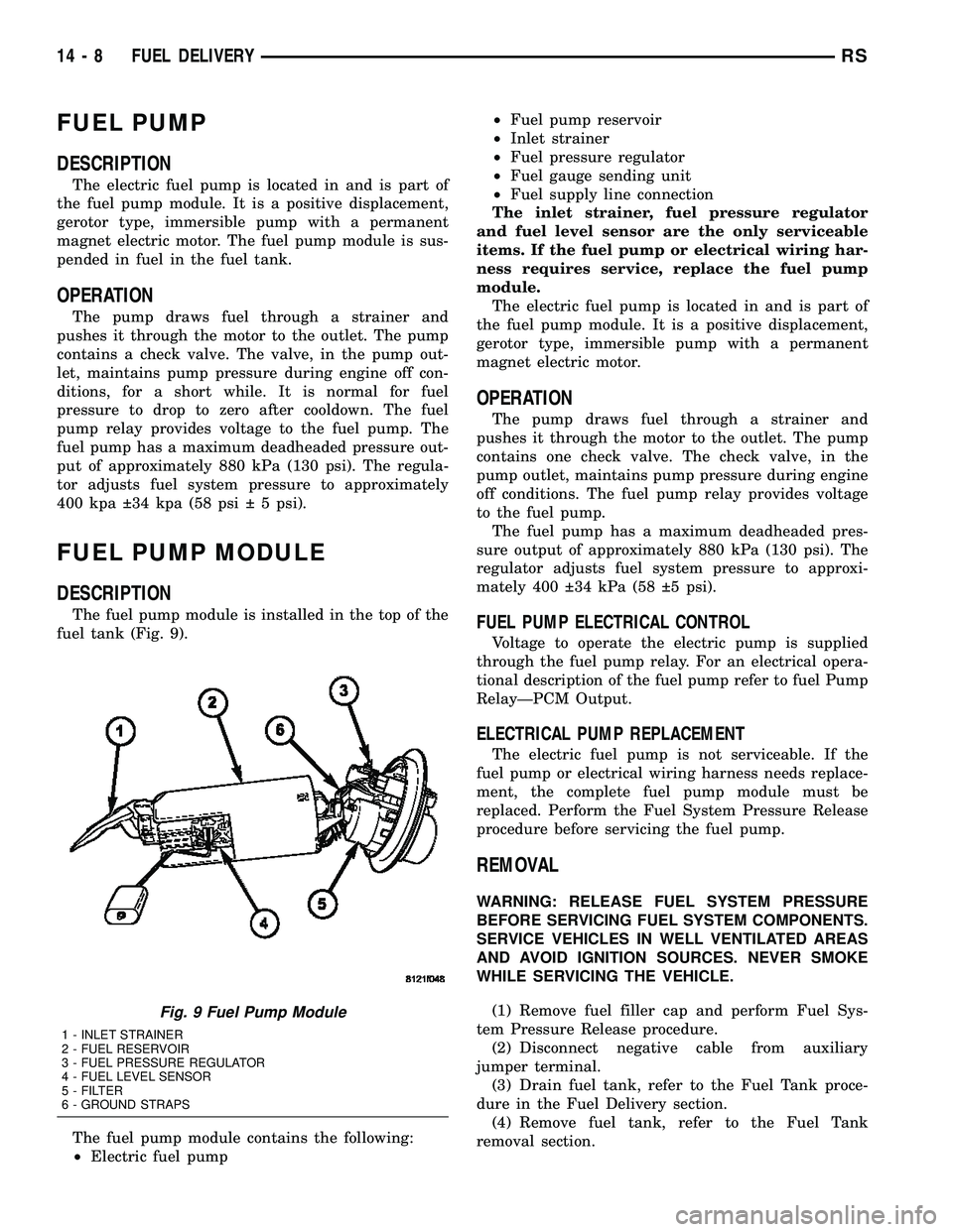
FUEL PUMP MODULE
DESCRIPTION
The fuel pump module is installed in the top of the
fuel tank (Fig. 9).
The fuel pump module contains the following:
²Electric fuel pump²Fuel pump reservoir
²Inlet strainer
²Fuel pressure regulator
²Fuel gauge sending unit
²Fuel supply line connection
The inlet strainer, fuel pressure regulator
and fuel level sensor are the only serviceable
items. If the fuel pump or electrical wiring har-
ness requires service, replace the fuel pump
module.
The electric fuel pump is located in and is part of
the fuel pump module. It is a positive displacement,
gerotor type, immersible pump with a permanent
magnet electric motor.
OPERATION
The pump draws fuel through a strainer and
pushes it through the motor to the outlet. The pump
contains one check valve. The check valve, in the
pump outlet, maintains pump pressure during engine
off conditions. The fuel pump relay provides voltage
to the fuel pump.
The fuel pump has a maximum deadheaded pres-
sure output of approximately 880 kPa (130 psi). The
regulator adjusts fuel system pressure to approxi-
mately 400 34 kPa (58 5 psi).
FUEL PUMP ELECTRICAL CONTROL
Voltage to operate the electric pump is supplied
through the fuel pump relay. For an electrical opera-
tional description of the fuel pump refer to fuel Pump
RelayÐPCM Output.
ELECTRICAL PUMP REPLACEMENT
The electric fuel pump is not serviceable. If the
fuel pump or electrical wiring harness needs replace-
ment, the complete fuel pump module must be
replaced. Perform the Fuel System Pressure Release
procedure before servicing the fuel pump.
REMOVAL
WARNING: RELEASE FUEL SYSTEM PRESSURE
BEFORE SERVICING FUEL SYSTEM COMPONENTS.
SERVICE VEHICLES IN WELL VENTILATED AREAS
AND AVOID IGNITION SOURCES. NEVER SMOKE
WHILE SERVICING THE VEHICLE.
(1) Remove fuel filler cap and perform Fuel Sys-
tem Pressure Release procedure.
(2) Disconnect negative cable from auxiliary
jumper terminal.
(3) Drain fuel tank, refer to the Fuel Tank proce-
dure in the Fuel Delivery section.
(4) Remove fuel tank, refer to the Fuel Tank
removal section.
Fig. 9 Fuel Pump Module
1 - INLET STRAINER
2 - FUEL RESERVOIR
3 - FUEL PRESSURE REGULATOR
4 - FUEL LEVEL SENSOR
5 - FILTER
6 - GROUND STRAPS
14 - 8 FUEL DELIVERYRS
Page 1516 of 2585
(5) Clean top of tank to remove loose dirt and
debris.
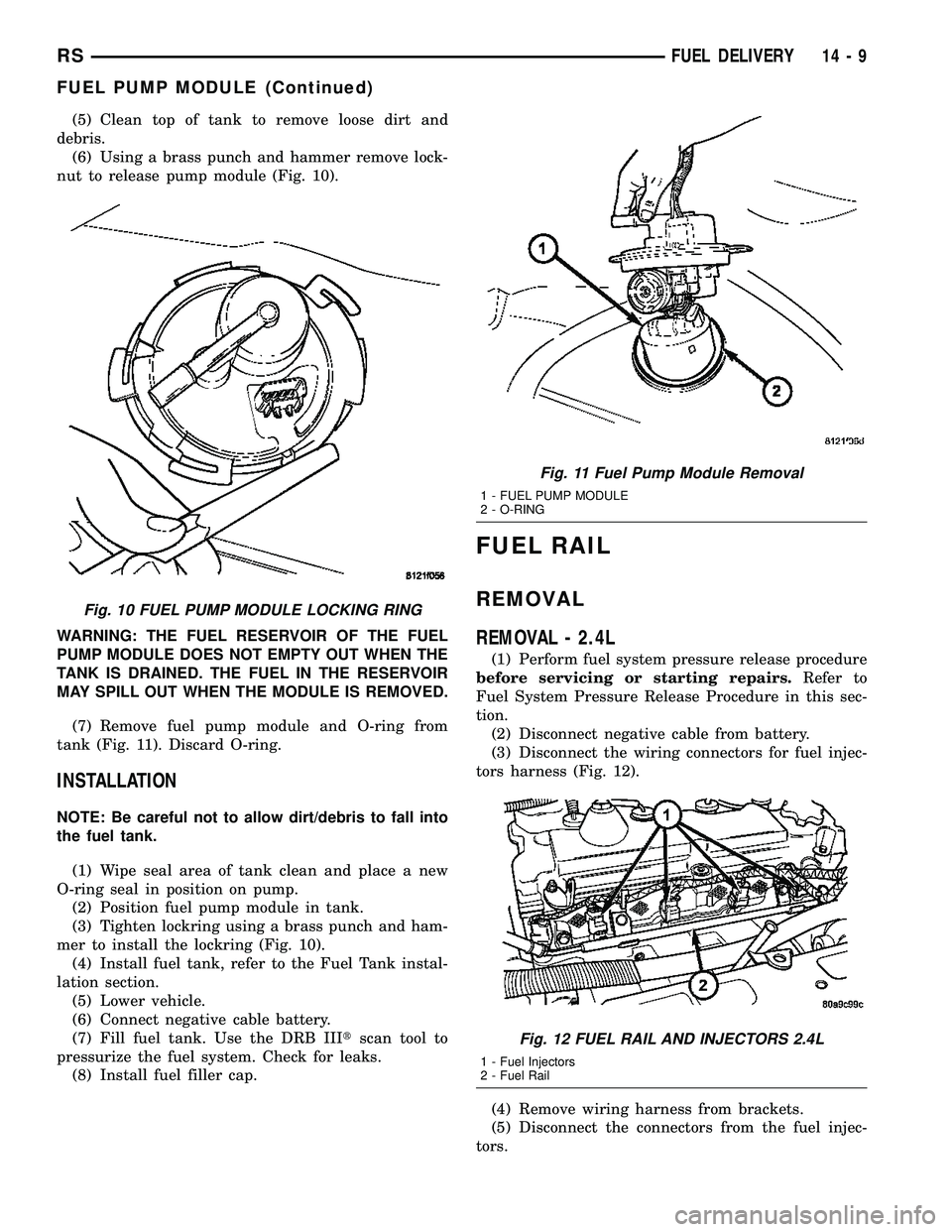
(6) Using a brass punch and hammer remove lock-
nut to release pump module (Fig. 10).
WARNING: THE FUEL RESERVOIR OF THE FUEL
PUMP MODULE DOES NOT EMPTY OUT WHEN THE
TANK IS DRAINED. THE FUEL IN THE RESERVOIR
MAY SPILL OUT WHEN THE MODULE IS REMOVED.
(7) Remove fuel pump module and O-ring from
tank (Fig. 11). Discard O-ring.
INSTALLATION
NOTE: Be careful not to allow dirt/debris to fall into
the fuel tank.
(1) Wipe seal area of tank clean and place a new
O-ring seal in position on pump.
(2) Position fuel pump module in tank.
(3) Tighten lockring using a brass punch and ham-
mer to install the lockring (Fig. 10).
(4) Install fuel tank, refer to the Fuel Tank instal-
lation section.
(5) Lower vehicle.
(6) Connect negative cable battery.
(7) Fill fuel tank. Use the DRB IIItscan tool to
pressurize the fuel system. Check for leaks.
(8) Install fuel filler cap.
FUEL RAIL
REMOVAL
REMOVAL - 2.4L
(1) Perform fuel system pressure release procedure
before servicing or starting repairs.Refer to
Fuel System Pressure Release Procedure in this sec-
tion.
(2) Disconnect negative cable from battery.
(3) Disconnect the wiring connectors for fuel injec-
tors harness (Fig. 12).
(4) Remove wiring harness from brackets.
(5) Disconnect the connectors from the fuel injec-
tors.
Fig. 10 FUEL PUMP MODULE LOCKING RING
Fig. 11 Fuel Pump Module Removal
1 - FUEL PUMP MODULE
2 - O-RING
Fig. 12 FUEL RAIL AND INJECTORS 2.4L
1 - Fuel Injectors
2 - Fuel Rail
RSFUEL DELIVERY14-9
FUEL PUMP MODULE (Continued)