2004 CHRYSLER VOYAGER Power system
[x] Cancel search: Power systemPage 2149 of 2585
CAUTION: Make note of cable routing and foam
insulator placement. This will prove helpful when
reinstalling replacement cable. Be certain replace-
ment cable is routed and retained correctly.
(7) Trace the inside handle cable along its routing
path and disconnect from its retaining clips.
(8) Disconnect the inside handle cable from the
latch assembly. Gently pry cable sleeve retainer out
of the latch mounting bracket and then unhook
swedged cable end from the latch link.
(9) Remove the inside handle cable from the side
door.
INSTALLATION
NOTE: For power sliding door procedures refer to
POWER SLIDING DOOR SYSTEM in the ELECTRI-
CAL section.
(1) Match the replacement cable up against the old
cable to verify the correct part.
(2) Position the inside handle cable on the side
door.
(3) Connect the inside handle cable on the handle
assembly. Hook the swedged cable end on the handle
link and gently push the cable sleeve retainer in the
handle bracket.
(4) Install the inside handle assembly on the side
door. (Refer to 23 - BODY/DOORS - SLIDING/IN-
SIDE LATCH HANDLE - INSTALLATION)
NOTE: The inside handle cable is marked with blue
tape and must be attached to the latch at the center
(just above the lower cable). This position is
marked with a ªBº on the latch.
(5) Connect the inside handle cable on the latch
assembly. Hook the swedged cable end on the latch
link and gently push the cable sleeve retainer in the
latch bracket.
(6) Trace the inside handle cable along its routing
path and install on its retaining clips and position
foam insulators. Use previously made schematic as a
guide or remove the opposite side door trim panel
and use that door as a guide.
CAUTION: Be certain replacement cable is routed
and retained correctly and foam insulators are
properly positioned.
(7) Install the latch assembly. Refer to the Power
Side Doors section for the procedure.
(8) Place the watershield into position and press
securely to adhesive making sure to properly route
wiring and linkages.(9) Install the appropriate side door trim panel on
the vehicle. (Refer to 23 - BODY/DOORS - SLIDING/
TRIM PANEL - INSTALLATION)
(10) Connect the negative battery cable.
HOLD OPEN LATCH CABLE
REMOVAL
NOTE: For power sliding door procedures refer to
POWER SLIDING DOOR SYSTEM in the ELECTRI-
CAL section.
(1) Disconnect and isolate the negative battery
cable.
(2) Remove the appropriate side door trim panel
from the vehicle. (Refer to 23 - BODY/DOORS -
SLIDING/TRIM PANEL - REMOVAL)
(3) Peel watershield away from adhesive around
perimeter of inner door panel.
(4) Open the side door and remove the latch
assembly. (Refer to 8 - ELECTRICAL/POWER
DOORS/LATCH - REMOVAL)
CAUTION: Make note of cable routing and foam
insulator placement. This will prove helpful when
reinstalling replacement cable. Be certain replace-
ment cable is routed and retained correctly.
(5) Trace the hold open latch cable along its rout-
ing path and disconnect from its retaining clips.
(6) Disconnect the hold open latch cable from the
latch assembly. Gently pry cable sleeve retainer out
of the latch mounting bracket and then unhook
swedged cable end from the latch link.
(7) Remove the hold open latch from the side door.
(Refer to 23 - BODY/DOORS - SLIDING/HOLD
OPEN LATCH - REMOVAL)
(8) Disconnect the hold open latch cable from the
hold open latch. Gently pry cable sleeve retainer out
of the handle bracket and then unhook swedged
cable end from the latch link.
(9) Remove the hold open latch cable from the side
door.
INSTALLATION
NOTE: For power sliding door procedures refer to
POWER SLIDING DOOR SYSTEM in the ELECTRI-
CAL section.
(1) Match the replacement cable up against the old
cable to verify the correct part.
(2) Position the hold open latch cable on the side
door.
23 - 38 DOORS - SLIDINGRS
INSIDE HANDLE CABLE (Continued)
Page 2220 of 2585
(4) Remove A-pillar trim panels.
(5) Place protective covers over instrument panel
and hood.
(6) Remove windshield molding. Using pliers, pull
outward on molding at the bottom of A-pillars.
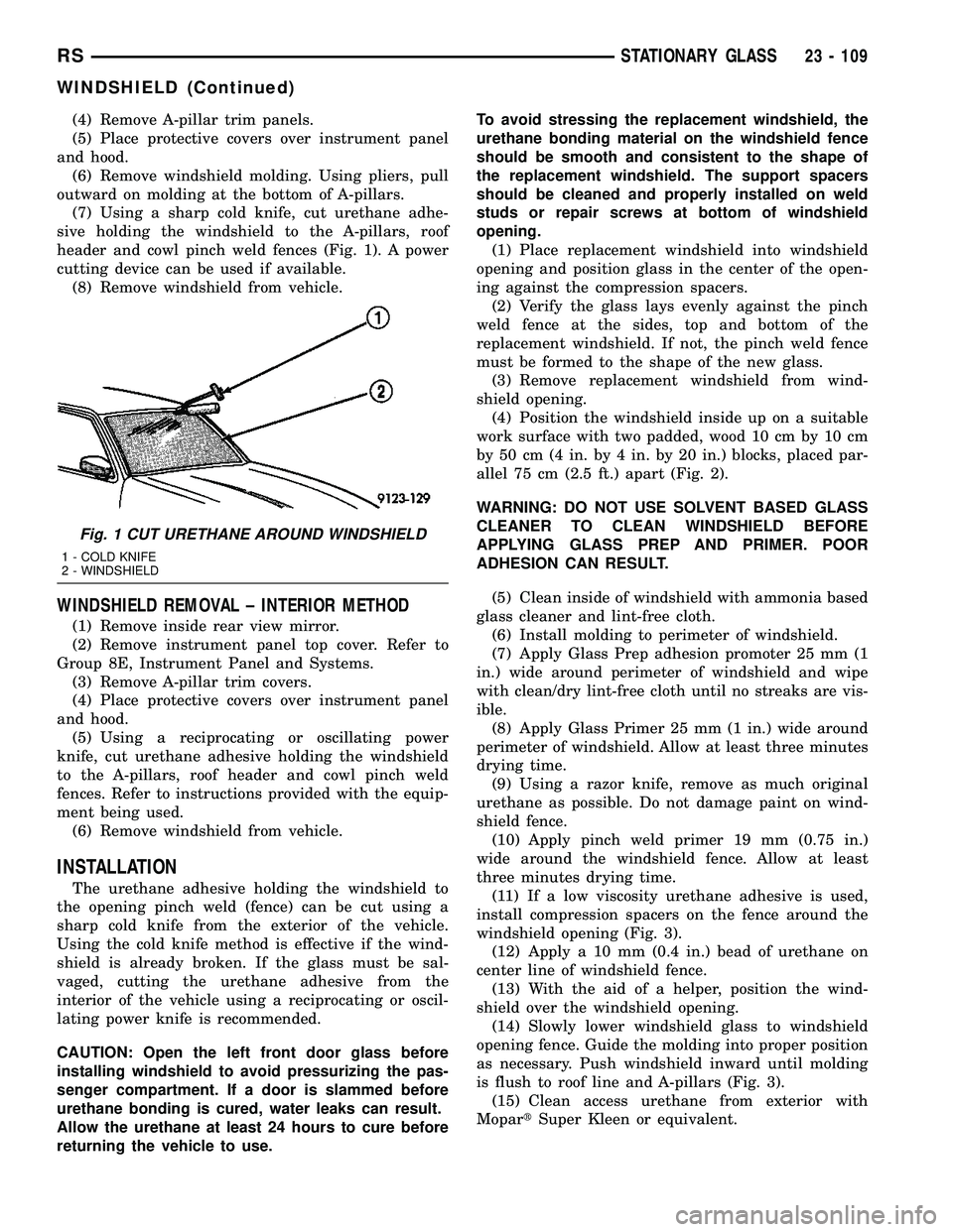
(7) Using a sharp cold knife, cut urethane adhe-
sive holding the windshield to the A-pillars, roof
header and cowl pinch weld fences (Fig. 1). A power
cutting device can be used if available.
(8) Remove windshield from vehicle.
WINDSHIELD REMOVAL ± INTERIOR METHOD
(1) Remove inside rear view mirror.
(2) Remove instrument panel top cover. Refer to
Group 8E, Instrument Panel and Systems.
(3) Remove A-pillar trim covers.
(4) Place protective covers over instrument panel
and hood.
(5) Using a reciprocating or oscillating power
knife, cut urethane adhesive holding the windshield
to the A-pillars, roof header and cowl pinch weld
fences. Refer to instructions provided with the equip-
ment being used.
(6) Remove windshield from vehicle.
INSTALLATION
The urethane adhesive holding the windshield to
the opening pinch weld (fence) can be cut using a
sharp cold knife from the exterior of the vehicle.
Using the cold knife method is effective if the wind-
shield is already broken. If the glass must be sal-
vaged, cutting the urethane adhesive from the
interior of the vehicle using a reciprocating or oscil-
lating power knife is recommended.
CAUTION: Open the left front door glass before
installing windshield to avoid pressurizing the pas-
senger compartment. If a door is slammed before
urethane bonding is cured, water leaks can result.
Allow the urethane at least 24 hours to cure before
returning the vehicle to use.To avoid stressing the replacement windshield, the
urethane bonding material on the windshield fence
should be smooth and consistent to the shape of
the replacement windshield. The support spacers
should be cleaned and properly installed on weld
studs or repair screws at bottom of windshield
opening.
(1) Place replacement windshield into windshield
opening and position glass in the center of the open-
ing against the compression spacers.
(2) Verify the glass lays evenly against the pinch
weld fence at the sides, top and bottom of the
replacement windshield. If not, the pinch weld fence
must be formed to the shape of the new glass.
(3) Remove replacement windshield from wind-
shield opening.
(4) Position the windshield inside up on a suitable
work surface with two padded, wood 10 cm by 10 cm
by 50 cm (4 in. by 4 in. by 20 in.) blocks, placed par-
allel 75 cm (2.5 ft.) apart (Fig. 2).
WARNING: DO NOT USE SOLVENT BASED GLASS
CLEANER TO CLEAN WINDSHIELD BEFORE
APPLYING GLASS PREP AND PRIMER. POOR
ADHESION CAN RESULT.
(5) Clean inside of windshield with ammonia based
glass cleaner and lint-free cloth.
(6) Install molding to perimeter of windshield.
(7) Apply Glass Prep adhesion promoter 25 mm (1
in.) wide around perimeter of windshield and wipe
with clean/dry lint-free cloth until no streaks are vis-
ible.
(8) Apply Glass Primer 25 mm (1 in.) wide around
perimeter of windshield. Allow at least three minutes
drying time.
(9) Using a razor knife, remove as much original
urethane as possible. Do not damage paint on wind-
shield fence.
(10) Apply pinch weld primer 19 mm (0.75 in.)
wide around the windshield fence. Allow at least
three minutes drying time.
(11) If a low viscosity urethane adhesive is used,
install compression spacers on the fence around the
windshield opening (Fig. 3).
(12) Apply a 10 mm (0.4 in.) bead of urethane on
center line of windshield fence.
(13) With the aid of a helper, position the wind-
shield over the windshield opening.
(14) Slowly lower windshield glass to windshield
opening fence. Guide the molding into proper position
as necessary. Push windshield inward until molding
is flush to roof line and A-pillars (Fig. 3).
(15) Clean access urethane from exterior with
MopartSuper Kleen or equivalent.
Fig. 1 CUT URETHANE AROUND WINDSHIELD
1 - COLD KNIFE
2 - WINDSHIELD
RSSTATIONARY GLASS23 - 109
WINDSHIELD (Continued)
Page 2222 of 2585
QUARTER WINDOW
REMOVAL
(1) Remove C-pillar trim.
(2) Open quarter glass to vent position.
(3) Disengage quarter window retainer from vent
motor arm.
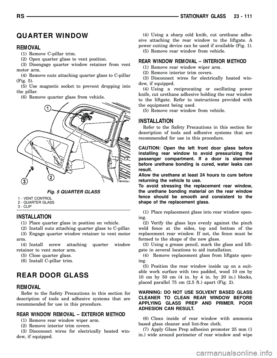
(4) Remove nuts attaching quarter glass to C-pillar
(Fig. 5).
(5) Use magnetic socket to prevent dropping into
the pillar.
(6) Remove quarter glass from vehicle.
INSTALLATION
(1) Place quarter glass in position on vehicle.
(2) Install nuts attaching quarter glass to C-pillar.
(3) Engage quarter window retainer to vent motor
arm.
(4) Install screw attaching quarter window
retainer to vent motor arm.
(5) Close quarter glass.
(6) Install C-pillar trim.
REAR DOOR GLASS
REMOVAL
Refer to the Safety Precautions in this section for
description of tools and adhesive systems that are
recommended for use in this procedure.
REAR WINDOW REMOVAL ± EXTERIOR METHOD
(1) Remove rear window wiper arm.
(2) Remove interior trim covers.
(3) Disconnect wires for electrically heated win-
dow, if equipped.(4) Using a sharp cold knife, cut urethane adhe-
sive attaching the rear window to the liftgate. A
power cutting device can be used if available (Fig. 1).
(5) Remove rear window from vehicle.
REAR WINDOW REMOVAL ± INTERIOR METHOD
(1) Remove rear window wiper arm.
(2) Remove interior trim covers.
(3) Disconnect wires for electrically heated win-
dow, if equipped.
(4) Using a reciprocating or oscillating power
knife, cut urethane adhesive holding the rear window
to the liftgate. Refer to instructions provided with
the equipment being used.
(5) Remove rear window from vehicle.
INSTALLATION
Refer to the Safety Precautions in this section for
description of tools and adhesive systems that are
recommended for use in this procedure.
CAUTION: Open the left front door glass before
installing rear window to avoid pressurizing the
passenger compartment. If a door is slammed
before urethane bonding is cured, water leaks can
result.
Allow the urethane at least 24 hours to cure before
returning the vehicle to use.
To avoid stressing the replacement rear window,
the urethane bonding material on the rear window
fence should be smooth and consistent to the
shape of the replacement glass.
(1) Place replacement glass into rear window open-
ing.
(2) Verify the glass lays evenly against the pinch
weld fence at the sides, top and bottom of the
replacement rear window. If not, the fence must be
formed to the shape of the new glass.
(3) Using a grease pencil, mark the glass and lift-
gate in several locations to aid installation.
(4) Remove replacement glass from liftgate open-
ing.
(5) Position the rear window inside up on a suit-
able work surface with two padded, wood 10 cm by
10 cm by 50 cm (4 in. by 4 in. by 20 in.) blocks,
placed parallel 75 cm (2.5 ft.) apart (Fig. 2).
WARNING: DO NOT USE SOLVENT BASED GLASS
CLEANER TO CLEAN REAR WINDOW BEFORE
APPLYING GLASS PREP AND PRIMER. POOR
ADHESION CAN RESULT.
(6) Clean inside of rear window with ammonia
based glass cleaner and lint-free cloth.
(7) Apply Glass Prep adhesion promoter 25 mm (1
in.) wide around perimeter of rear window and wipe
Fig. 5 QUARTER GLASS
1 - VENT CONTROL
2 - QUARTER GLASS
3 - CLIP
RSSTATIONARY GLASS23 - 111
Page 2227 of 2585
SUNROOF
TABLE OF CONTENTS
page page
SUNROOF
DESCRIPTION........................116
DIAGNOSIS AND TESTING - SUNROOF.....116
DRAIN TUBE
REMOVAL............................119
INSTALLATION........................120
GLASS PANEL
REMOVAL............................120
INSTALLATION........................120
ADJUSTMENTS
SUNROOF GLASS PANEL ADJUSTMENT . . 120
SUNROOF ASSEMBLY
REMOVAL............................120
INSTALLATION........................120
SUNSHADE
REMOVAL............................120INSTALLATION........................121
WIND DEFLECTOR
REMOVAL............................121
INSTALLATION........................121
WATER CHANNEL
REMOVAL............................121
INSTALLATION........................121
SUNROOF MOTOR
REMOVAL............................121
INSTALLATION........................121
ADJUSTMENTS
ADJUSTMENT.......................122
SUNROOF SWITCH
REMOVAL............................123
INSTALLATION........................123
SUNROOF
DESCRIPTION
WARNING: Keep fingers and other body parts out
of sunroof opening at all times.
The sun roof features consists of: (Fig. 1)
²Sun roof glass
²Sun roof sun shade
The sunroof power sliding glass panel and sun-
shade can be positioned anywhere along its travel,
rearward of glass panel front edge.
The sunroof is electrically operated from a switch
located in the overhead console. To operate the sun-
roof the ignition switch must be in the Accessory or
On/Run position. Both switchs are a rocker style
design that open or close the sunroof. When pressing
and releasing the open button once, the sunroof will
express open to the comfort stop and the wind deflec-
tor will raise. If the button is pressed a second time,
the sunroof will continue to open to full travel unless
the button is released, at which time it will stop in
that position. Pressing and holding the close button
will close the sunroof. If the close button is released
before the glass fully closes, the sunroof will stop in
that position. The vent switch operates in a similar
manor. The sunroof will also operate for up to fifteenminutes after the ignition key is turned off for cus-
tomer comfort and convenance while parking.
DIAGNOSIS AND TESTING - SUNROOF
Refer to Sunroof Diagnostic Chart for possible
causes. Before beginning sunroof diagnostics verify
that all other power accessories are in proper operat-
ing condition. If not, a common electrical problem
may exist. Refer to Wiring Diagrams, in this publica-
tion for circuit, splice and component descriptions.
Check the condition of the circuit protection (20 amp
circuit breaker in the Junction Block). Inspect all
wiring connector pins for proper engagement and
continuity. Check for battery voltage at the power
sunroof controller, refer to Wiring Diagrams, for cir-
cuit information. If battery voltage of more than 10
volts is detected at the controller, proceed with the
following tests (the controller will not operate at less
than 10 volts).
Before beginning diagnosis for wind noise or water
leaks, verify that the problem was not caused by
releasing the control switch before the sunroof was
fully closed. The sunroof module has a water-man-
agement system. If however, the sunroof glass is in a
partial closed position, high pressure water may be
forced beyond the water management system bound-
aries and onto the headlining.
23 - 116 SUNROOFRS
Page 2396 of 2585
HEATING & AIR CONDITIONING
TABLE OF CONTENTS
page page
HEATING & AIR CONDITIONING
DESCRIPTION
DESCRIPTION - ENGINE COOLING
SYSTEM REQUIREMENTS...............1
DESCRIPTION - HEATER AND AIR
CONDITIONER........................1
DESCRIPTION - SINGLE ZONE...........2
DESCRIPTION - DUAL ZONE.............2
DESCRIPTION - MANUAL THREE ZONE.....2
DESCRIPTION - AUTOMATIC THREE ZONE . . 3
OPERATION
OPERATION - HEATER AND AIR
CONDITIONER........................4
OPERATION - SINGLE ZONE.............4
OPERATION - DUAL ZONE...............5
OPERATION - MANUAL THREE ZONE......5
OPERATION - THREE ZONE ATC..........5DIAGNOSIS AND TESTING
DIAGNOSIS AND TESTING - A/C COOL
DOWN TEST..........................6
DIAGNOSIS AND TESTING - A/C
PERFORMANCE TEST..................7
DIAGNOSIS AND TESTING - HEATER
PERFORMANCE TEST.................10
SPECIFICATIONS
A/C SYSTEM.........................11
CONTROLS - FRONT.....................14
CONTROLS - REAR......................34
DISTRIBUTION - FRONT...................43
DISTRIBUTION - REAR....................56
PLUMBING - FRONT.....................64
PLUMBING - REAR......................97
CABIN HEATER........................112
HEATING & AIR
CONDITIONING
DESCRIPTION
DESCRIPTION - ENGINE COOLING SYSTEM
REQUIREMENTS
To maintain the performance level of the heating,
ventilation and air conditioning (HVAC) system, the
engine cooling system must be properly maintained.
The use of a bug screen is not recommended. Any
obstructions in front of the radiator or condenser will
reduce the performance of the air conditioning and
engine cooling systems.
The engine cooling system includes the radiator,
thermostat, radiator hoses and the engine coolant
pump. Refer to Cooling for more information before
opening or attempting any service to the engine cool-
ing system.
DESCRIPTION - HEATER AND AIR
CONDITIONER
A manually controlled single zone type heating-air
conditioning system, manually controlled dual zone
type heating-air conditioning system, manually con-
trolled three zone type heating-air conditioning sys-
tem or an automatic controlled three zone typeheating-air conditioning system is available on this
model.
All vehicles are equipped with a common heater,
ventilation and air conditioning (HVAC) housing (Fig.
1). The system combines air conditioning, heating,
and ventilating capabilities in a single unit housing
mounted within the passenger compartment under
the instrument panel. The HVAC housing includes:
²Blower motor
²Blower motor resistor block or power module
(depending on application)
²Heater core
²Evaporator coil
²Blend door and actuator
²Mode door and actuator
²Recirculation door and actuator
Based upon the system and mode selected, condi-
tioned air can exit the HVAC housing through one or
a combination of the three main housing outlets:
defrost, panel or floor. The defrost and panel outlets
are located on the top of the housing and the floor
outlet is located on the bottom of the housing. Once
the conditioned air exits the unit housing, it is fur-
ther directed through molded plastic ducts to the var-
ious outlets in the vehicle interior. These outlets and
their locations are as follows:
²Defroster Outlet- A single large defroster out-
let is located in the center of the instrument panel
top cover, near the base of the windshield.
²Side Window Demister Outlets- There are
two side window demister outlets, one is located at
RSHEATING & AIR CONDITIONING24-1
Page 2398 of 2585
REAR CONTROL PANEL
The rear A/C-heater control centrally mounted in
the headliner allows intermediate seat passengers to
adjust rear air distribution, temperature and blower
motor speed when the center knob on the front A/C-
heater control is set to the Rear position. The rear
A/C-heater control contains:
²a rotary adjustment knob for temperature.
²a rotary adjustment for fan speed control.
DESCRIPTION - AUTOMATIC THREE ZONE
The automatic temperature control (ATC), three
zone, front and rear heating and air conditioning sys-
tem allows both the driver and front occupants and
the rear intermediate occupants to select individual
comfort temperatures.
NOTE: Individual comfort temperatures are the per-
ceived temperature level at the individual seating
areas, NOT the actual passenger compartment air
temperature.
The ATC system includes a particulate air filter.
The filter element is the same size as the air condi-
tioning evaporator to ensure ample capacity. A door
at the base of the HVAC housing below the glove box
provides easy access to the filter element.
The ATC computer utilizes integrated circuitry and
information carried on the programmable communi-
cations interface (PCI) data bus network to monitor
many sensors and switch inputs throughout the vehi-
cle. In response to those inputs, the internal circuitry
and programming of the ATC computer allow it to
control electronic functions and features of the ATC
system. The inputs to the ATC computer are:
²Vehicle Speed/Engine RPM± The ATC com-
puter monitors engine rpm, vehicle speed and mani-
fold absolute pressure information from the
powertrain control module (PCM).
²Coolant Temperature± ATC computer moni-
tors coolant temperature received from the PCM and
converts it to degrees Fahrenheit.
²Ambient Temperature± ATC computer moni-
tors ambient temperature from the compass mini trip
computer (CMTC) and converts it to degrees Fahren-
heit.
²Engine Miscellaneous Sensor Status±ATC
computer monitors A/C disable information from the
PCM.
²Refrigerant Pressure± ATC computer moni-
tors barometric pressure, intake air temperature,
high side pressure and methanol content as broad-
cast by the PCM.
²Door Ajar Status± The ATC computer moni-
tors driver front door, passenger front door, left rear
door, right rear door and liftgate ajar information, asidentified by the body control module (BCM), to
determine if all in-car temperatures should be main-
tained.
²Dimming± The ATC computer monitors dim-
ming status from the BCM to determine the required
level of brightness and will dim accordingly.
²Vehicle Odometer± The ATC computer moni-
tors the vehicle odometer information from the BCM
to prevent flashing the vacuum-flourescent (VF) dig-
ital display icons if the manual motor calibration or
manual cool down tests have failed. Flashing of the
display icons will cease when the vehicle odometer is
greater than 3 miles.
²English/Metric± The ATC computer monitors
the English/Metric information broadcast by the
CMTC. The set temp displays for both the front and
rear control heads will be set accordingly.
²Vehicle Identification Number± The ATC
computer monitors the last eight characters of the
VIN broadcast by the PCM and compares it to the
information stored in EEPROM. If it is different, the
new number will be stored over the old one and a
motor calibration shall be initiated.
²A/C System Information± The ATC computer
will send a message for evaporator temperature too
low, fan blower relay status, evaporator sensor fail-
ure, rear window defogger relay and A/C select.
FRONT CONTROL PANEL
The front A/C-heater control and integral computer
is mounted in the instrument panel and contains:
²a power button which allows the system to be
completely turned off. The display is blank when the
system is off.
²a rocker switch that selects a cool-down rate.
LO-AUTO or HI-AUTO are displayed when the sys-
tem is in automatic operation.
²three rocker switches that select comfort temper-
atures from 15É to 30É C (59É to 85É F), which are
shown in the VF digital display. If the set temp is 15É
C (59É F) and the down button is pressed, the set
temp value will become 13É C (55É F) but the display
will show LO. If the set temp is 29É C (85É F) and the
up button is pressed, the set temp value will become
32É C (90É F) but the display will show HIGH. Tem-
peratures can be displayed in either metric or Fahr-
enheit, which is controlled from the overhead console.
²an air conditioning button that allows the com-
pressor to be turned off. A Snowflake symbol is illu-
minated when air conditioning is on, whether under
manual or automatic control.
²an air recirculation button. A Recirculation sym-
bol appears in the display when the button is
pressed, or when the system exceeds 80 percent cir-
culated air under automatic control due to high air
conditioning demand.
RSHEATING & AIR CONDITIONING24-3
HEATING & AIR CONDITIONING (Continued)
Page 2400 of 2585
OPERATION - DUAL ZONE
²The two slide controls enable continuously vari-
able proportioning of the conditioned air.
²The mode control knob enables continuously
variable proportioning of air flow between modes and
has detents adjacent to each icon.
²The blower control provides four separate speeds
and an Off position.
²When the heater-A/C system is off, the HVAC
computer closes the recirculation door to prevent out-
side air from entering the passenger compartment.
²Interior air may be recirculated to speed up
heating or cooling in all modes except defrost and
mix by pressing the Recirculate button on the A/C-
heater control.
²To reduce humidity for rapid defogging, the A/C
compressor runs automatically in modes from ªmixº
to full defrost when outside temperatures are above
freezing.
²Air conditioning is available in any mode by
pressing the snowflake, A/C on/off button.
OPERATION - MANUAL THREE ZONE
FRONT CONTROL PANEL
²Primary control of the rear heater-A/C system is
on the instrument panel. This control allows the
driver to set the rear compartment fan speed, to turn
the rear heater-A/C system off, or to give control to
the intermediate seat occupants by switching to the
Rear position. When the rear heater-A/C system is
controlled from the instrument panel, rear air tem-
perature is based on the driver-side temperature con-
trol position, and the mode (floor or overhead air) is
based on the front control's mode position.
²The mode control knob enables continuously
variable proportioning of air flow between modes but
has detents adjacent to each icon.
²The blower control provides four separate speeds
and an Off position. When the heater-A/C system is
off, the HVAC computer closes the recirculation door
to prevent outside air from entering the passenger
compartment.
²Interior air may be recirculated to speed up
heating or cooling in all modes except defrost and
mix by pressing the Recirculate button on the control
panel.
²To reduce humidity for rapid defogging the A/C
compressor runs automatically in modes from ªmix'
to full defrost when outside temperatures are above
freezing.
²Air conditioning is available in any mode by
pressing the snowflake, A/C on/off, button.
REAR CONTROL PANEL
With the rear control active, temperature selection
dictates the air distribution mode (floor or overhead
air) of the rear unit: a cool temperature setting
directs flow to the overhead outlets and a warm tem-
perature setting to the floor.
OPERATION - THREE ZONE ATC
Comfort temperature or perceived temperature is
affected by air flow, sun levels on exposed skin, etc. The
air temperature may be higher or lower than the com-
fort temperature. Two infrared sensors in the instru-
ment panel center stack measure the temperature of
the occupants to determine their comfort level relative
to the selected comfort temperature. The integral
HVAC computer adjusts temperature and air flow rates
to maintain the customer-perceived comfort tempera-
ture. The air temperature in the passenger compart-
ment may be slightly higher or lower than the comfort
temperature at any time. For instance, on sunny sum-
mer days the air flow will probably be cooler than the
comfort temperature; on cold or cloudy days and at
night it will probably be slightly warmer. Infrared
Three-Zone Temperature Control provides side-to-side
and front-to-rear variations in comfort temperature set-
tings. The Infrared Three-Zone Automatic Temperature
Control fan provides a continuously variable air flow
rate to meet occupant comfort requirements.
FRONT CONTROL PANEL
²AUTO HI/LO± This system features two sets of
automatic control logic that allow either a rapid cool-
down rate or a somewhat slower cool-down rate with
less fan noise. HI-AUTO controls the system to reach
its assigned temperature quickly with a higher fan
speed. LO-AUTO controls the system to reach its
assigned temperature somewhat slower with less fan
noise. Both modes will automatically engage auto
recirculation.
²DE-FROST± The defrost function is active
when the rear window defogger function is active or
when the defog/defrost mode is selected.
²RECIRC± The RECIRC button will close the
air inlet door. If the system is in auto recirc (indica-
tor being displayed automatically), pressing the man-
ual recirc button will disable the auto recirc function
until one of the auto keys are pressed or the ignition
is cycled. If Auto HI/LO is pressed while manual
recirc is active, manual recirc will be deactivated.
²REAR WINDOW DEFOGGER± Pushing the
button sends a PCI bus message to the Intelligent
Power Module which controls the Rear Window
Defogger and side view mirror (if equipped) circuitry.
The defogger function will be active for 10 minutes
and can be turned off by a switch press. The defogger
will function while the control is in the ON mode.
RSHEATING & AIR CONDITIONING24-5
HEATING & AIR CONDITIONING (Continued)
Page 2403 of 2585
A/C PERFORMANCE TEMPERATURE AND PRESSURE
Ambient Temperature21É C
(70É F)27É C
(80É F)32É C
(90É F)38É C
(100É F)43É C
(110É F)
Left Center Panel
Outlet Discharge Air
Temperature1to8ÉC
(34 to 46É F)3to9ÉC
(37 to 49É F)4 to 10ÉC
(39 to 50É F)6to11ÉC
(43 to 52É F)7 to 18É C
(45 to 65É F)
Discharge Pressure
(High Side Service
Port)1034 to 1724
kPa
(150 to 250 psi)1517 to 2275
kPa
(220 to 330
psi)1999 to 2620
kPa
(290 to 380 psi)2068 to 2965
kPa
(300 to 430 psi)2275 to 3421
kPa
(330 to 450
psi)
Suction Pressure
(Low Side Service
Port)103 to 207 kPa
(15 to 30 psi)117to221
kPa
(17 to 32 psi)138 to 241 kPa
(20 to 35 psi)172 to 269 kPa
(25 to 39 psi)207 to 345
kPa
(30 to 50 psi)
(8) If the air outlet temperature fails to meet the
specifications in the A/C Performance Temperature
and Pressure chart, or if the compressor dischargepressure is high, refer to the Pressure Diagnosis
Chart.
PRESSURE DIAGNOSIS
Condition Possible Causes Correction
Rapid A/C compressor clutch
cycling (ten or more cycles
per minute).1. Low refrigerant system
charge.1. See Refrigerant System Leaks in this group.
Test the refrigerant system for leaks. Repair,
evacuate and charge the refrigerant system, if
required.
Equal pressures, but the
compressor clutch does not
engage.1. No refrigerant in the
refrigerant system.1. See Refrigerant System Leaks in this group.
Test the refrigerant system for leaks. Repair,
evacuate and charge the refrigerant system, if
required.
2. Faulty fuse. 2. Check the fuses in the Integrated Power
Module. Repair the shorted circuit or component
and replace the fuses, if required. Refer to Group
8.
3. Faulty A/C compressor
clutch coil.3. See A/C Compressor Clutch Coil in this group.
Test the compressor clutch coil and replace, if
required.
4. Faulty A/C compressor
clutch relay.4. See A/C Compressor Clutch Relay in this
group. Test the compressor clutch relay and relay
circuits. Repair the circuits or replace the relay, if
required.
5. Improperly installed or
faulty evaporator temperature
sensor.5. See Evaporator Temperature Sensor in this
group. Test the sensor and replace, if required.
6. Faulty A/C pressure
transducer.6. See A/C Pressure Transducer in this group.
Test the sensor and replace, if required.
7. Faulty Powertrain Control
Module (PCM).7. Refer to the proper Diagnostic Procedures
manual for testing of the PCM. Test the PCM and
replace, if required.
24 - 8 HEATING & AIR CONDITIONINGRS
HEATING & AIR CONDITIONING (Continued)