2004 CHRYSLER VOYAGER width
[x] Cancel search: widthPage 1402 of 2585
(4) When seat is properly positioned the width of
intake and exhaust seats should be 1.50±2.00 mm
(0.059±0.078 in.) (Fig. 27).
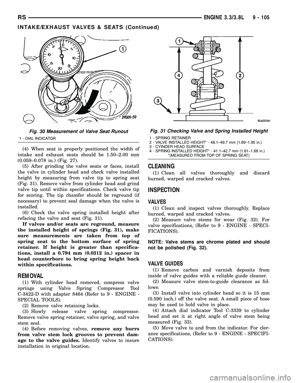
(5) After grinding the valve seats or faces, install
the valve in cylinder head and check valve installed
height by measuring from valve tip to spring seat
(Fig. 31). Remove valve from cylinder head and grind
valve tip until within specifications. Check valve tip
for scoring. The tip chamfer should be reground (if
necessary) to prevent seal damage when the valve is
installed.
(6) Check the valve spring installed height after
refacing the valve and seat (Fig. 31).
If valves and/or seats are reground, measure
the installed height of springs (Fig. 31), make
sure measurements are taken from top of
spring seat to the bottom surface of spring
retainer. If height is greater than specifica-
tions, install a 0.794 mm (0.0312 in.) spacer in
head counterbore to bring spring height back
within specifications.
REMOVAL
(1) With cylinder head removed, compress valve
springs using Valve Spring Compressor Tool
C-3422-D with adapter 8464 (Refer to 9 - ENGINE -
SPECIAL TOOLS).
(2) Remove valve retaining locks.
(3) Slowly release valve spring compressor.
Remove valve spring retainer, valve spring, and valve
stem seal.
(4) Before removing valves,remove any burrs
from valve stem lock grooves to prevent dam-
age to the valve guides.Identify valves to insure
installation in original location.
CLEANING
(1) Clean all valves thoroughly and discard
burned, warped and cracked valves.
INSPECTION
VALVES
(1) Clean and inspect valves thoroughly. Replace
burned, warped and cracked valves.
(2) Measure valve stems for wear (Fig. 32). For
valve specifications, (Refer to 9 - ENGINE - SPECI-
FICATIONS).
NOTE: Valve stems are chrome plated and should
not be polished (Fig. 32).
VALVE GUIDES
(1) Remove carbon and varnish deposits from
inside of valve guides with a reliable guide cleaner.
(2) Measure valve stem-to-guide clearance as fol-
lows:
(3) Install valve into cylinder head so it is 15 mm
(0.590 inch.) off the valve seat. A small piece of hose
may be used to hold valve in place.
(4) Attach dial indicator Tool C-3339 to cylinder
head and set it at right angle of valve stem being
measured (Fig. 33).
(5) Move valve to and from the indicator. For cler-
ance specifications, (Refer to 9 - ENGINE - SPECIFI-
CATIONS).
Fig. 30 Measurement of Valve Seat Runout
1 - DIAL INDICATOR
Fig. 31 Checking Valve and Spring Installed Height
1 - SPRING RETAINER
2 - VALVE INSTALLED HEIGHT* - 48.1±49.7 mm (1.89±1.95 in.)
3 - CYINDER HEAD SURFACE
4 - SPRING INSTALLED HEIGHT* - 41.1±42.7 mm (1.61±1.68 in.)
*(MEASURED FROM TOP OF SPRING SEAT)
RSENGINE 3.3/3.8L9 - 105
INTAKE/EXHAUST VALVES & SEATS (Continued)
Page 1417 of 2585
CONNECTING ROD BEARINGS
STANDARD PROCEDURE - MEASURING
CONNECTING ROD BEARING CLEARANCE
The bearing caps are not interchangeable and
should be marked at removal to ensure correct
assembly. The bearing shells must be installed with
the tangs inserted into the machined grooves in the
rods and caps. Install cap with the tangs on the same
side as the rod. Fit all rods on one bank until com-
plete. Connecting rod bearings are available in the
standard size and the following undersizes: 0.025
mm (0.001 in.) and 0.250 mm (0.010 in.).
CAUTION: Install the bearings in pairs. Do not use a
new bearing half with an old bearing half. Do not
file the rods or bearing caps.Measure connecting rod journal for taper and out-
of-round. (Refer to 9 - ENGINE/ENGINE BLOCK/
CRANKSHAFT - INSPECTION)
The connecting rod bearing clearances can be
determined by use of Plastigage or the equivalent.
The following is the recommended procedure for the
use of Plastigage:
(1) Rotate the crankshaft until the connecting rod
to be checked is at the bottom of its stroke.
(2) Remove oil film from surface to be checked.
Plastigage is soluble in oil.
(3) Place a piece of Plastigage across the entire
width of the bearing shell in the bearing cap approx-
imately 6.35 mm (1/4 in.) off center and away from
the oil hole. In addition, suspect areas can be
checked by placing Plastigage in that area.
(4) Assemble the rod cap with Plastigage in place.
Tighten the rod cap to the specified torque.Do not
rotate the crankshaft while assembling the cap
or the Plastigage may be smeared, giving inac-
curate results.
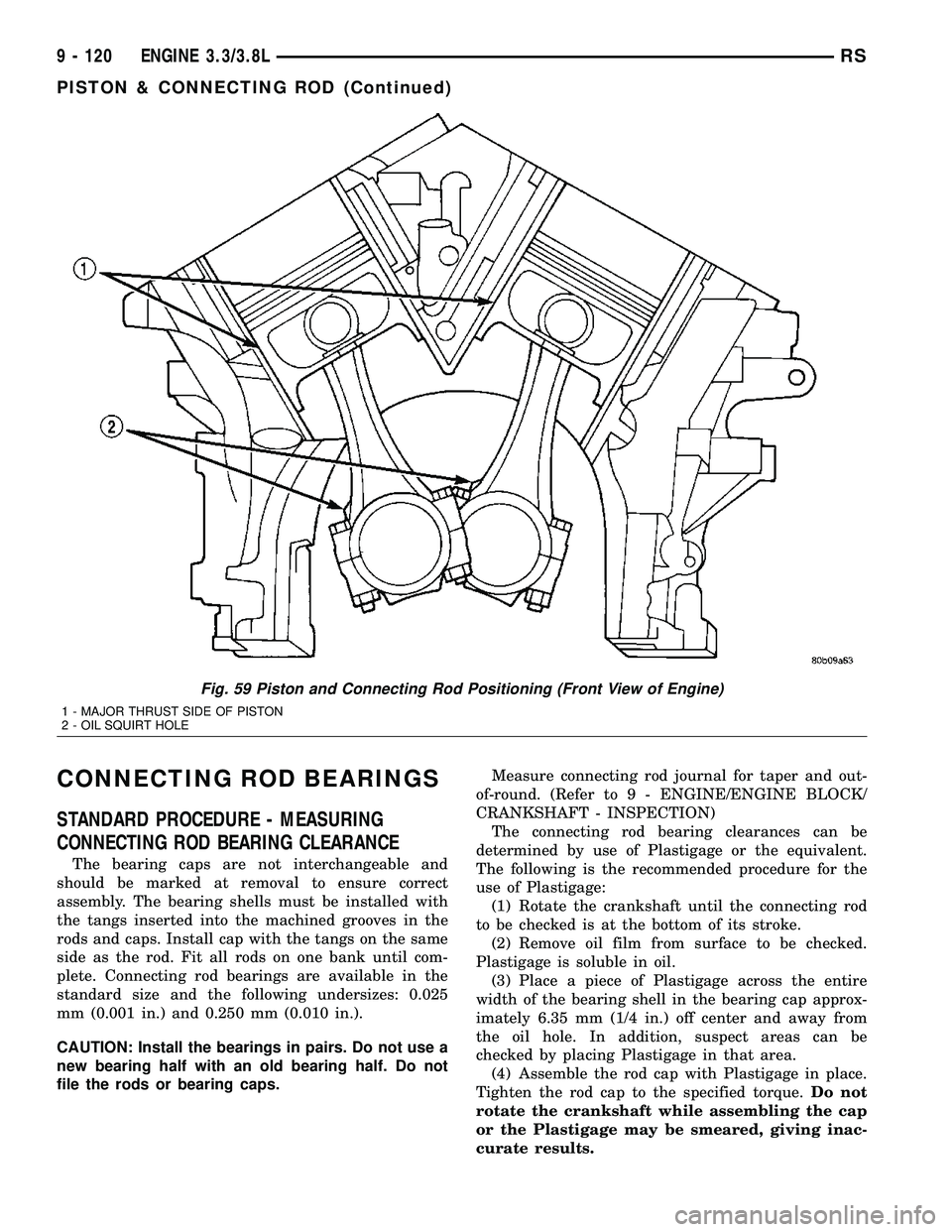
Fig. 59 Piston and Connecting Rod Positioning (Front View of Engine)
1 - MAJOR THRUST SIDE OF PISTON
2 - OIL SQUIRT HOLE
9 - 120 ENGINE 3.3/3.8LRS
PISTON & CONNECTING ROD (Continued)
Page 1418 of 2585
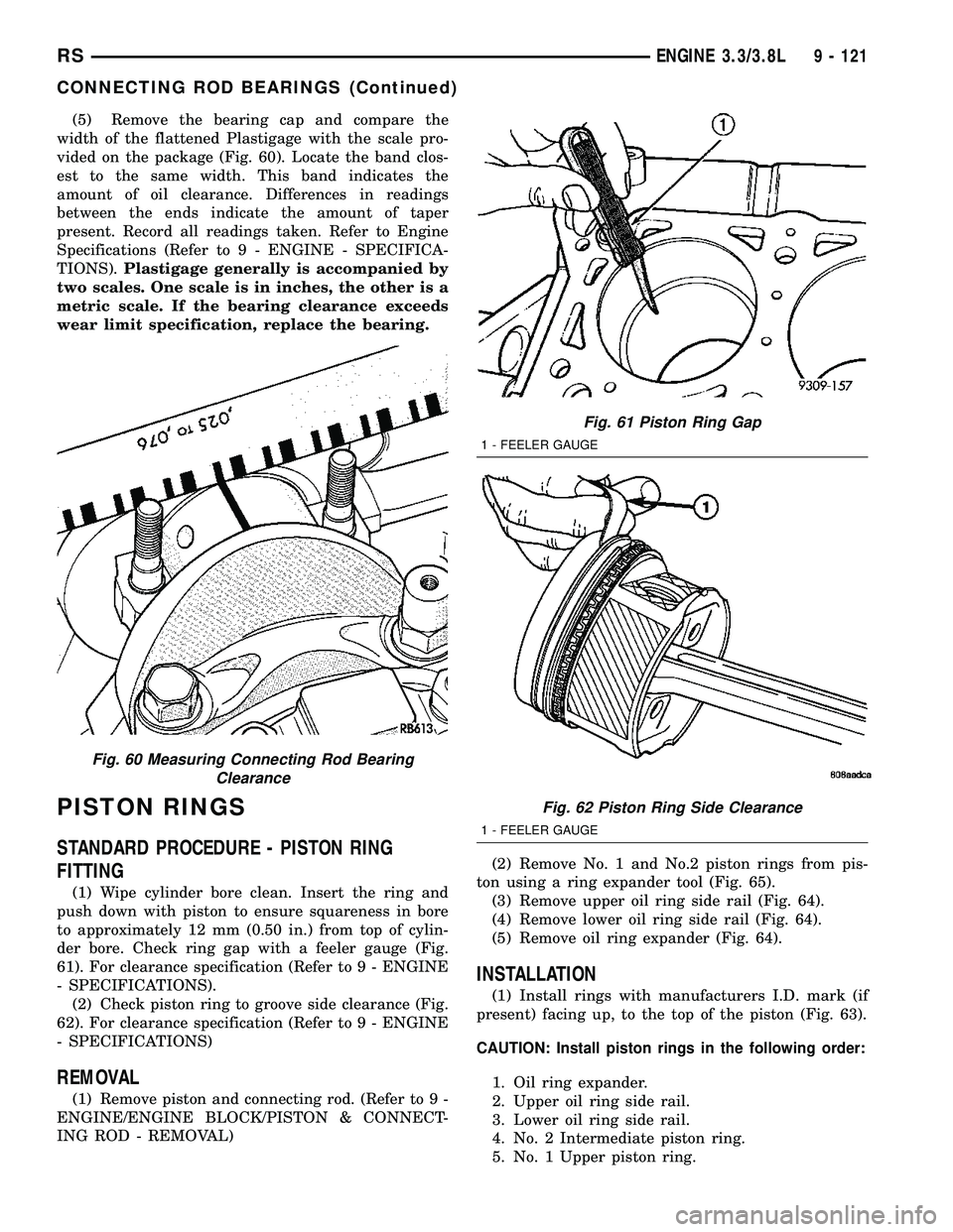
(5) Remove the bearing cap and compare the
width of the flattened Plastigage with the scale pro-
vided on the package (Fig. 60). Locate the band clos-
est to the same width. This band indicates the
amount of oil clearance. Differences in readings
between the ends indicate the amount of taper
present. Record all readings taken. Refer to Engine
Specifications (Refer to 9 - ENGINE - SPECIFICA-
TIONS).Plastigage generally is accompanied by
two scales. One scale is in inches, the other is a
metric scale. If the bearing clearance exceeds
wear limit specification, replace the bearing.
PISTON RINGS
STANDARD PROCEDURE - PISTON RING
FITTING
(1) Wipe cylinder bore clean. Insert the ring and
push down with piston to ensure squareness in bore
to approximately 12 mm (0.50 in.) from top of cylin-
der bore. Check ring gap with a feeler gauge (Fig.
61). For clearance specification (Refer to 9 - ENGINE
- SPECIFICATIONS).
(2) Check piston ring to groove side clearance (Fig.
62). For clearance specification (Refer to 9 - ENGINE
- SPECIFICATIONS)
REMOVAL
(1) Remove piston and connecting rod. (Refer to 9 -
ENGINE/ENGINE BLOCK/PISTON & CONNECT-
ING ROD - REMOVAL)(2) Remove No. 1 and No.2 piston rings from pis-
ton using a ring expander tool (Fig. 65).
(3) Remove upper oil ring side rail (Fig. 64).
(4) Remove lower oil ring side rail (Fig. 64).
(5) Remove oil ring expander (Fig. 64).
INSTALLATION
(1) Install rings with manufacturers I.D. mark (if
present) facing up, to the top of the piston (Fig. 63).
CAUTION: Install piston rings in the following order:
1. Oil ring expander.
2. Upper oil ring side rail.
3. Lower oil ring side rail.
4. No. 2 Intermediate piston ring.
5. No. 1 Upper piston ring.
Fig. 60 Measuring Connecting Rod Bearing
Clearance
Fig. 61 Piston Ring Gap
1 - FEELER GAUGE
Fig. 62 Piston Ring Side Clearance
1 - FEELER GAUGE
RSENGINE 3.3/3.8L9 - 121
CONNECTING ROD BEARINGS (Continued)
Page 1421 of 2585
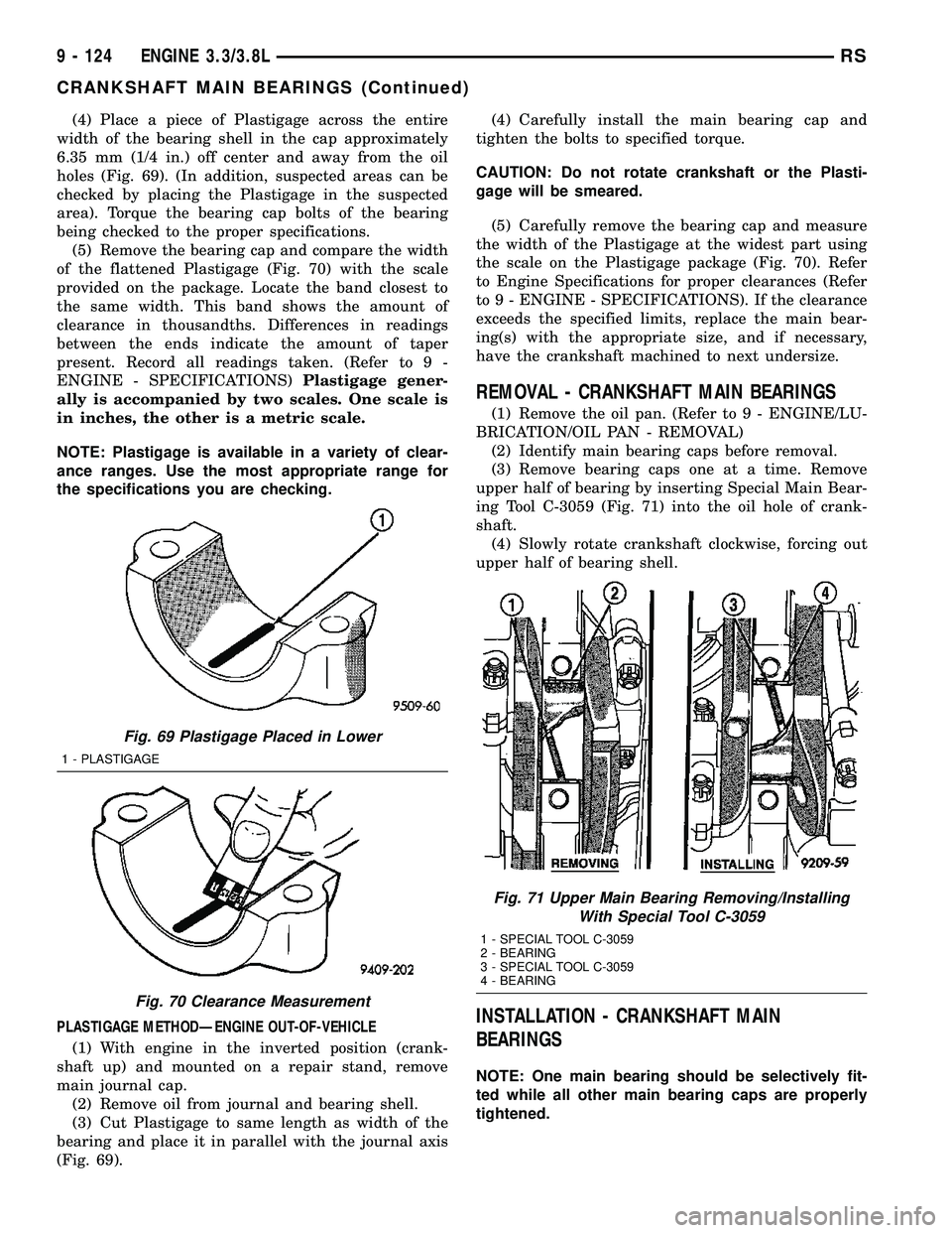
(4) Place a piece of Plastigage across the entire
width of the bearing shell in the cap approximately
6.35 mm (1/4 in.) off center and away from the oil
holes (Fig. 69). (In addition, suspected areas can be
checked by placing the Plastigage in the suspected
area). Torque the bearing cap bolts of the bearing
being checked to the proper specifications.
(5) Remove the bearing cap and compare the width
of the flattened Plastigage (Fig. 70) with the scale
provided on the package. Locate the band closest to
the same width. This band shows the amount of
clearance in thousandths. Differences in readings
between the ends indicate the amount of taper
present. Record all readings taken. (Refer to 9 -
ENGINE - SPECIFICATIONS)Plastigage gener-
ally is accompanied by two scales. One scale is
in inches, the other is a metric scale.
NOTE: Plastigage is available in a variety of clear-
ance ranges. Use the most appropriate range for
the specifications you are checking.
PLASTIGAGE METHODÐENGINE OUT-OF-VEHICLE
(1) With engine in the inverted position (crank-
shaft up) and mounted on a repair stand, remove
main journal cap.
(2) Remove oil from journal and bearing shell.
(3) Cut Plastigage to same length as width of the
bearing and place it in parallel with the journal axis
(Fig. 69).(4) Carefully install the main bearing cap and
tighten the bolts to specified torque.
CAUTION: Do not rotate crankshaft or the Plasti-
gage will be smeared.
(5) Carefully remove the bearing cap and measure
the width of the Plastigage at the widest part using
the scale on the Plastigage package (Fig. 70). Refer
to Engine Specifications for proper clearances (Refer
to 9 - ENGINE - SPECIFICATIONS). If the clearance
exceeds the specified limits, replace the main bear-
ing(s) with the appropriate size, and if necessary,
have the crankshaft machined to next undersize.
REMOVAL - CRANKSHAFT MAIN BEARINGS
(1) Remove the oil pan. (Refer to 9 - ENGINE/LU-
BRICATION/OIL PAN - REMOVAL)
(2) Identify main bearing caps before removal.
(3) Remove bearing caps one at a time. Remove
upper half of bearing by inserting Special Main Bear-
ing Tool C-3059 (Fig. 71) into the oil hole of crank-
shaft.
(4) Slowly rotate crankshaft clockwise, forcing out
upper half of bearing shell.
INSTALLATION - CRANKSHAFT MAIN
BEARINGS
NOTE: One main bearing should be selectively fit-
ted while all other main bearing caps are properly
tightened.
Fig. 69 Plastigage Placed in Lower
1 - PLASTIGAGE
Fig. 70 Clearance Measurement
Fig. 71 Upper Main Bearing Removing/Installing
With Special Tool C-3059
1 - SPECIAL TOOL C-3059
2 - BEARING
3 - SPECIAL TOOL C-3059
4 - BEARING
9 - 124 ENGINE 3.3/3.8LRS
CRANKSHAFT MAIN BEARINGS (Continued)
Page 1457 of 2585
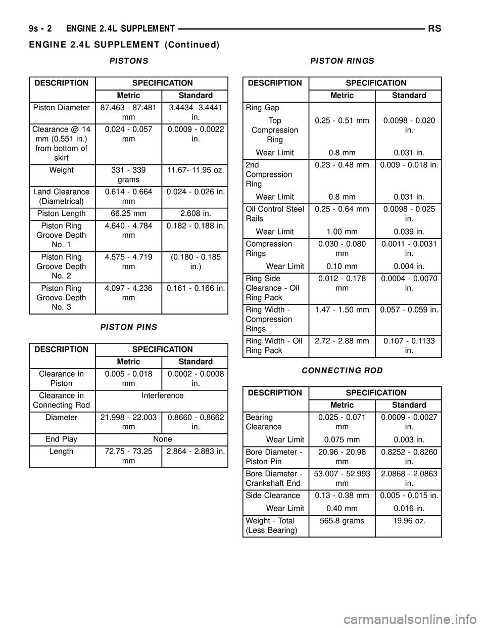
PISTONS
DESCRIPTION SPECIFICATION
Metric Standard
Piston Diameter 87.463 - 87.481
mm3.4434 -3.4441
in.
Clearance @ 14
mm (0.551 in.)
from bottom of
skirt0.024 - 0.057
mm0.0009 - 0.0022
in.
Weight 331 - 339
grams11.67- 11.95 oz.
Land Clearance
(Diametrical)0.614 - 0.664
mm0.024 - 0.026 in.
Piston Length 66.25 mm 2.608 in.
Piston Ring
Groove Depth
No. 14.640 - 4.784
mm0.182 - 0.188 in.
Piston Ring
Groove Depth
No. 24.575 - 4.719
mm(0.180 - 0.185
in.)
Piston Ring
Groove Depth
No. 34.097 - 4.236
mm0.161 - 0.166 in.
PISTON PINS
DESCRIPTION SPECIFICATION
Metric Standard
Clearance in
Piston0.005 - 0.018
mm0.0002 - 0.0008
in.
Clearance in
Connecting RodInterference
Diameter 21.998 - 22.003
mm0.8660 - 0.8662
in.
End Play None
Length 72.75 - 73.25
mm2.864 - 2.883 in.
PISTON RINGS
DESCRIPTION SPECIFICATION
Metric Standard
Ring Gap
To p
Compression
Ring0.25 - 0.51 mm 0.0098 - 0.020
in.
Wear Limit 0.8 mm 0.031 in.
2nd
Compression
Ring0.23 - 0.48 mm 0.009 - 0.018 in.
Wear Limit 0.8 mm 0.031 in.
Oil Control Steel
Rails0.25 - 0.64 mm 0.0098 - 0.025
in.
Wear Limit 1.00 mm 0.039 in.
Compression
Rings0.030 - 0.080
mm0.0011 - 0.0031
in.
Wear Limit 0.10 mm 0.004 in.
Ring Side
Clearance - Oil
Ring Pack0.012 - 0.178
mm0.0004 - 0.0070
in.
Ring Width -
Compression
Rings1.47 - 1.50 mm 0.057 - 0.059 in.
Ring Width - Oil
Ring Pack2.72 - 2.88 mm 0.107 - 0.1133
in.
CONNECTING ROD
DESCRIPTION SPECIFICATION
Metric Standard
Bearing
Clearance0.025 - 0.071
mm0.0009 - 0.0027
in.
Wear Limit 0.075 mm 0.003 in.
Bore Diameter -
Piston Pin20.96 - 20.98
mm0.8252 - 0.8260
in.
Bore Diameter -
Crankshaft End53.007 - 52.993
mm2.0868 - 2.0863
in.
Side Clearance 0.13 - 0.38 mm 0.005 - 0.015 in.
Wear Limit 0.40 mm 0.016 in.
Weight - Total
(Less Bearing)565.8 grams 19.96 oz.
9s - 2 ENGINE 2.4L SUPPLEMENTRS
ENGINE 2.4L SUPPLEMENT (Continued)
Page 1459 of 2585
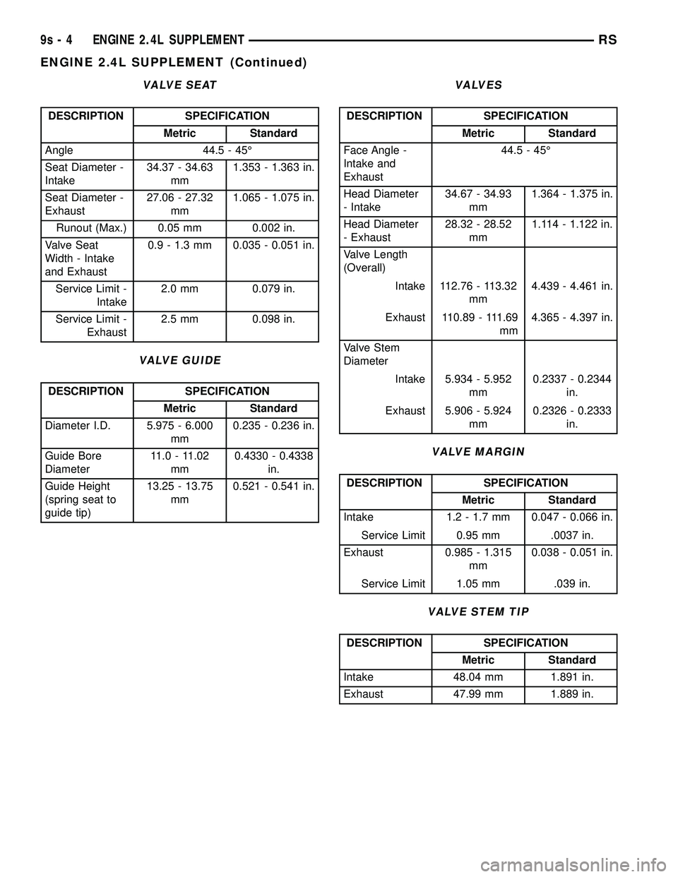
VALVE SEAT
DESCRIPTION SPECIFICATION
Metric Standard
Angle 44.5 - 45É
Seat Diameter -
Intake34.37 - 34.63
mm1.353 - 1.363 in.
Seat Diameter -
Exhaust27.06 - 27.32
mm1.065 - 1.075 in.
Runout (Max.) 0.05 mm 0.002 in.
Valve Seat
Width - Intake
and Exhaust0.9 - 1.3 mm 0.035 - 0.051 in.
Service Limit -
Intake2.0 mm 0.079 in.
Service Limit -
Exhaust2.5 mm 0.098 in.
VALVE GUIDE
DESCRIPTION SPECIFICATION
Metric Standard
Diameter I.D. 5.975 - 6.000
mm0.235 - 0.236 in.
Guide Bore
Diameter11.0 - 11.02
mm0.4330 - 0.4338
in.
Guide Height
(spring seat to
guide tip)13.25 - 13.75
mm0.521 - 0.541 in.
VALVES
DESCRIPTION SPECIFICATION
Metric Standard
Face Angle -
Intake and
Exhaust44.5 - 45É
Head Diameter
- Intake34.67 - 34.93
mm1.364 - 1.375 in.
Head Diameter
- Exhaust28.32 - 28.52
mm1.114 - 1.122 in.
Valve Length
(Overall)
Intake 112.76 - 113.32
mm4.439 - 4.461 in.
Exhaust 110.89 - 111.69
mm4.365 - 4.397 in.
Valve Stem
Diameter
Intake 5.934 - 5.952
mm0.2337 - 0.2344
in.
Exhaust 5.906 - 5.924
mm0.2326 - 0.2333
in.
VALVE MARGIN
DESCRIPTION SPECIFICATION
Metric Standard
Intake 1.2 - 1.7 mm 0.047 - 0.066 in.
Service Limit 0.95 mm .0037 in.
Exhaust 0.985 - 1.315
mm0.038 - 0.051 in.
Service Limit 1.05 mm .039 in.
VALVE STEM TIP
DESCRIPTION SPECIFICATION
Metric Standard
Intake 48.04 mm 1.891 in.
Exhaust 47.99 mm 1.889 in.
9s - 4 ENGINE 2.4L SUPPLEMENTRS
ENGINE 2.4L SUPPLEMENT (Continued)
Page 1467 of 2585
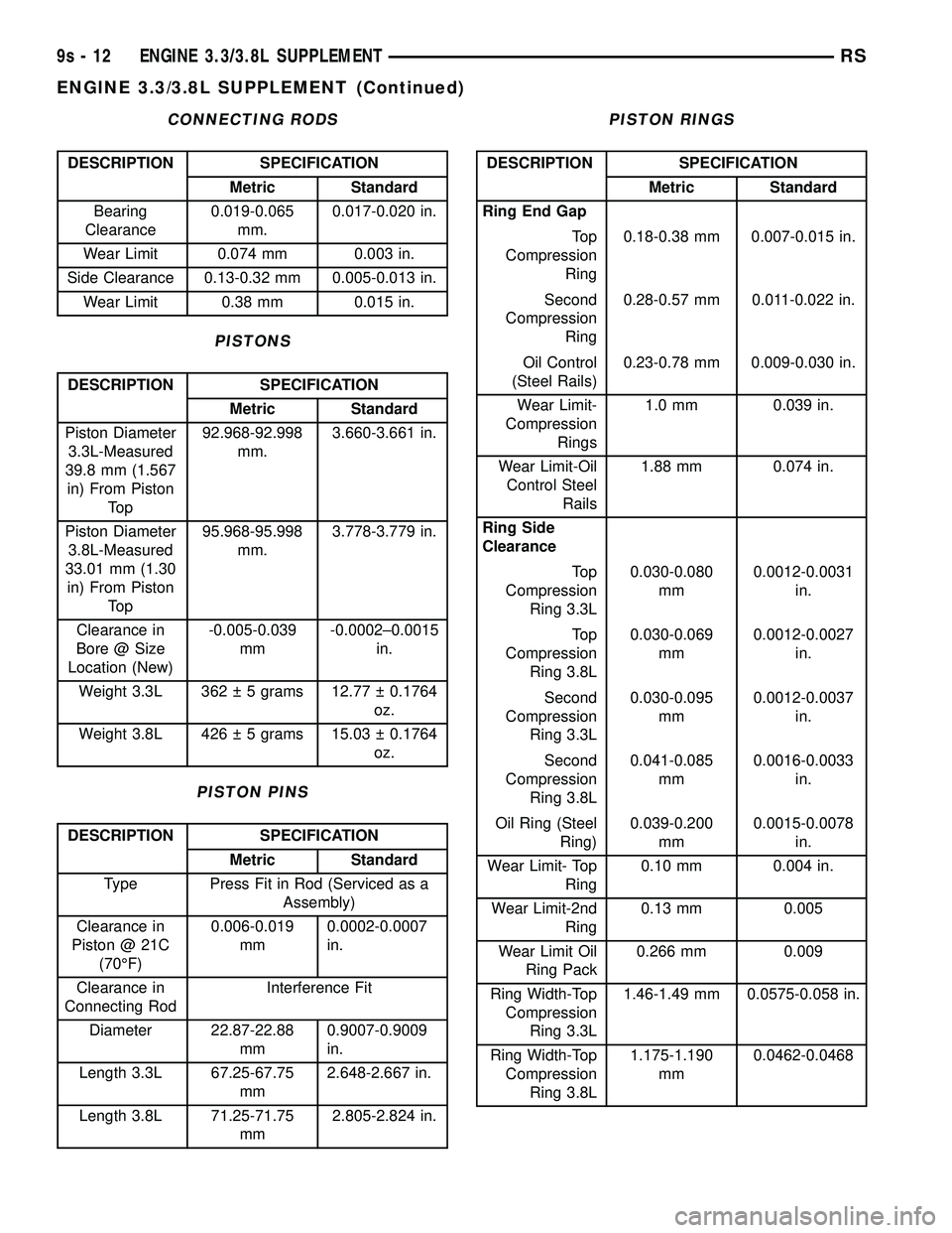
CONNECTING RODS
DESCRIPTION SPECIFICATION
Metric Standard
Bearing
Clearance0.019-0.065
mm.0.017-0.020 in.
Wear Limit 0.074 mm 0.003 in.
Side Clearance 0.13-0.32 mm 0.005-0.013 in.
Wear Limit 0.38 mm 0.015 in.
PISTONS
DESCRIPTION SPECIFICATION
Metric Standard
Piston Diameter
3.3L-Measured
39.8 mm (1.567
in) From Piston
To p92.968-92.998
mm.3.660-3.661 in.
Piston Diameter
3.8L-Measured
33.01 mm (1.30
in) From Piston
To p95.968-95.998
mm.3.778-3.779 in.
Clearance in
Bore @ Size
Location (New)-0.005-0.039
mm-0.0002±0.0015
in.
Weight 3.3L 362 5 grams 12.77 0.1764
oz.
Weight 3.8L 426 5 grams 15.03 0.1764
oz.
PISTON PINS
DESCRIPTION SPECIFICATION
Metric Standard
Type Press Fit in Rod (Serviced as a
Assembly)
Clearance in
Piston @ 21C
(70ÉF)0.006-0.019
mm0.0002-0.0007
in.
Clearance in
Connecting RodInterference Fit
Diameter 22.87-22.88
mm0.9007-0.9009
in.
Length 3.3L 67.25-67.75
mm2.648-2.667 in.
Length 3.8L 71.25-71.75
mm2.805-2.824 in.
PISTON RINGS
DESCRIPTION SPECIFICATION
Metric Standard
Ring End Gap
To p
Compression
Ring0.18-0.38 mm 0.007-0.015 in.
Second
Compression
Ring0.28-0.57 mm 0.011-0.022 in.
Oil Control
(Steel Rails)0.23-0.78 mm 0.009-0.030 in.
Wear Limit-
Compression
Rings1.0 mm 0.039 in.
Wear Limit-Oil
Control Steel
Rails1.88 mm 0.074 in.
Ring Side
Clearance
To p
Compression
Ring 3.3L0.030-0.080
mm0.0012-0.0031
in.
To p
Compression
Ring 3.8L0.030-0.069
mm0.0012-0.0027
in.
Second
Compression
Ring 3.3L0.030-0.095
mm0.0012-0.0037
in.
Second
Compression
Ring 3.8L0.041-0.085
mm0.0016-0.0033
in.
Oil Ring (Steel
Ring)0.039-0.200
mm0.0015-0.0078
in.
Wear Limit- Top
Ring0.10 mm 0.004 in.
Wear Limit-2nd
Ring0.13 mm 0.005
Wear Limit Oil
Ring Pack0.266 mm 0.009
Ring Width-Top
Compression
Ring 3.3L1.46-1.49 mm 0.0575-0.058 in.
Ring Width-Top
Compression
Ring 3.8L1.175-1.190
mm0.0462-0.0468
9s - 12 ENGINE 3.3/3.8L SUPPLEMENTRS
ENGINE 3.3/3.8L SUPPLEMENT (Continued)
Page 1468 of 2585
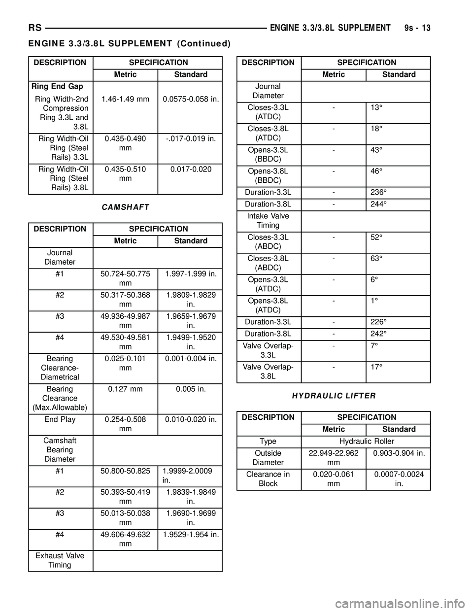
DESCRIPTION SPECIFICATION
Metric Standard
Ring End Gap
Ring Width-2nd
Compression
Ring 3.3L and
3.8L1.46-1.49 mm 0.0575-0.058 in.
Ring Width-Oil
Ring (Steel
Rails) 3.3L0.435-0.490
mm-.017-0.019 in.
Ring Width-Oil
Ring (Steel
Rails) 3.8L0.435-0.510
mm0.017-0.020
CAMSHAFT
DESCRIPTION SPECIFICATION
Metric Standard
Journal
Diameter
#1 50.724-50.775
mm1.997-1.999 in.
#2 50.317-50.368
mm1.9809-1.9829
in.
#3 49.936-49.987
mm1.9659-1.9679
in.
#4 49.530-49.581
mm1.9499-1.9520
in.
Bearing
Clearance-
Diametrical0.025-0.101
mm0.001-0.004 in.
Bearing
Clearance
(Max.Allowable)0.127 mm 0.005 in.
End Play 0.254-0.508
mm0.010-0.020 in.
Camshaft
Bearing
Diameter
#1 50.800-50.825 1.9999-2.0009
in.
#2 50.393-50.419
mm1.9839-1.9849
in.
#3 50.013-50.038
mm1.9690-1.9699
in.
#4 49.606-49.632
mm1.9529-1.954 in.
Exhaust Valve
Timing
DESCRIPTION SPECIFICATION
Metric Standard
Journal
Diameter
Closes-3.3L
(ATDC)- 13É
Closes-3.8L
(ATDC)- 18É
Opens-3.3L
(BBDC)- 43É
Opens-3.8L
(BBDC)- 46É
Duration-3.3L - 236É
Duration-3.8L - 244É
Intake Valve
Timing
Closes-3.3L
(ABDC)- 52É
Closes-3.8L
(ABDC)- 63É
Opens-3.3L
(ATDC)-6É
Opens-3.8L
(ATDC)-1É
Duration-3.3L - 226É
Duration-3.8L - 242É
Valve Overlap-
3.3L-7É
Valve Overlap-
3.8L- 17É
HYDRAULIC LIFTER
DESCRIPTION SPECIFICATION
Metric Standard
Type Hydraulic Roller
Outside
Diameter22.949-22.962
mm0.903-0.904 in.
Clearance in
Block0.020-0.061
mm0.0007-0.0024
in.
RSENGINE 3.3/3.8L SUPPLEMENT9s-13
ENGINE 3.3/3.8L SUPPLEMENT (Continued)