2004 CHRYSLER VOYAGER width
[x] Cancel search: widthPage 2097 of 2585
white letters. To remove the protective coating, apply
warm water and let it soak for a few minutes. After-
wards, scrub the coating away with a soft bristle
brush. Steam cleaning may also be used to remove
the coating.
CAUTION: DO NOT use gasoline, mineral oil, oil-
based solvent or a wire brush for cleaning.
WHEELS
DESCRIPTION - WHEEL
Original equipment wheels are designed for proper
operation at all loads up to the specified maximum
vehicle capacity.
All models use either steel or aluminum drop-cen-
ter wheels. Every wheel has raised sections between
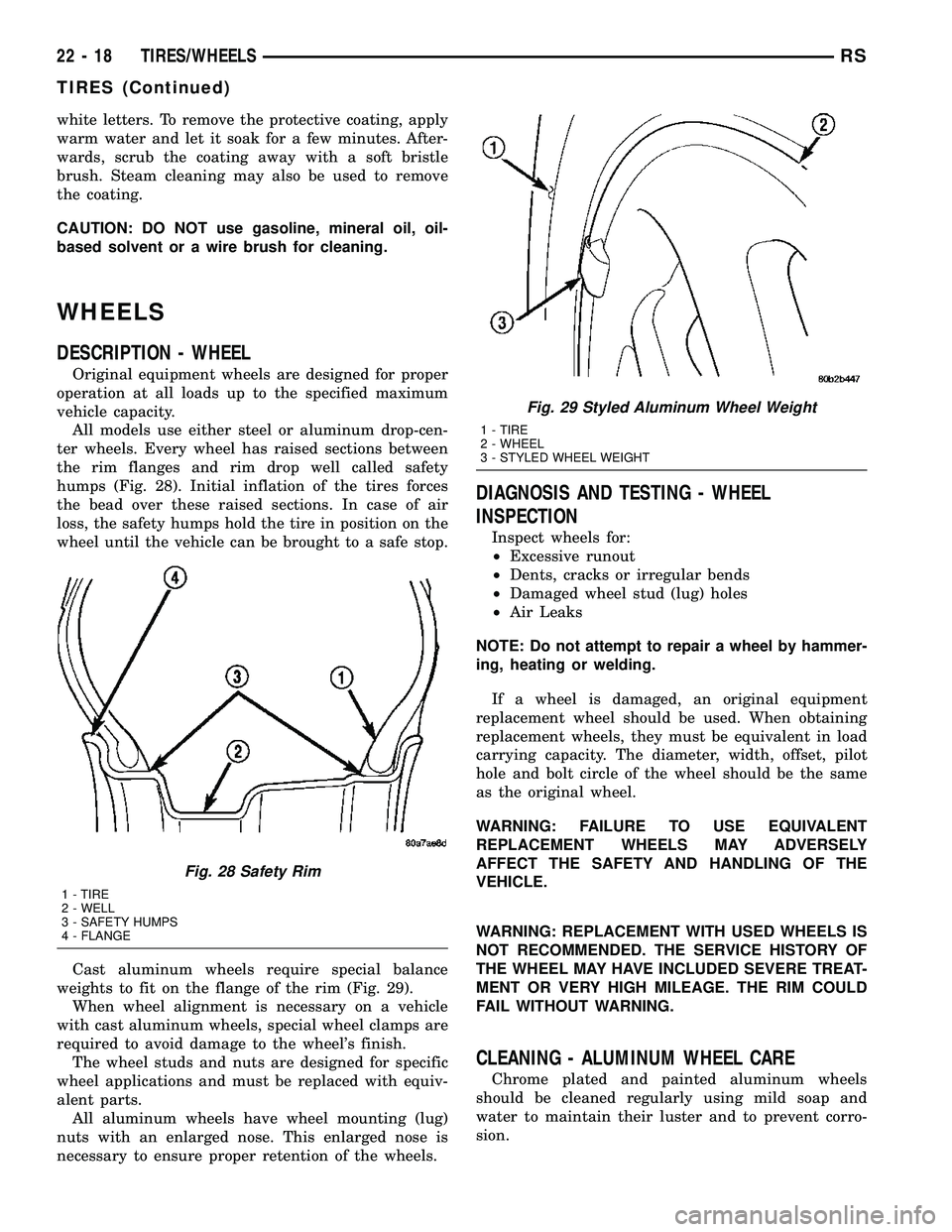
the rim flanges and rim drop well called safety
humps (Fig. 28). Initial inflation of the tires forces
the bead over these raised sections. In case of air
loss, the safety humps hold the tire in position on the
wheel until the vehicle can be brought to a safe stop.
Cast aluminum wheels require special balance
weights to fit on the flange of the rim (Fig. 29).
When wheel alignment is necessary on a vehicle
with cast aluminum wheels, special wheel clamps are
required to avoid damage to the wheel's finish.
The wheel studs and nuts are designed for specific
wheel applications and must be replaced with equiv-
alent parts.
All aluminum wheels have wheel mounting (lug)
nuts with an enlarged nose. This enlarged nose is
necessary to ensure proper retention of the wheels.
DIAGNOSIS AND TESTING - WHEEL
INSPECTION
Inspect wheels for:
²Excessive runout
²Dents, cracks or irregular bends
²Damaged wheel stud (lug) holes
²Air Leaks
NOTE: Do not attempt to repair a wheel by hammer-
ing, heating or welding.
If a wheel is damaged, an original equipment
replacement wheel should be used. When obtaining
replacement wheels, they must be equivalent in load
carrying capacity. The diameter, width, offset, pilot
hole and bolt circle of the wheel should be the same
as the original wheel.
WARNING: FAILURE TO USE EQUIVALENT
REPLACEMENT WHEELS MAY ADVERSELY
AFFECT THE SAFETY AND HANDLING OF THE
VEHICLE.
WARNING: REPLACEMENT WITH USED WHEELS IS
NOT RECOMMENDED. THE SERVICE HISTORY OF
THE WHEEL MAY HAVE INCLUDED SEVERE TREAT-
MENT OR VERY HIGH MILEAGE. THE RIM COULD
FAIL WITHOUT WARNING.
CLEANING - ALUMINUM WHEEL CARE
Chrome plated and painted aluminum wheels
should be cleaned regularly using mild soap and
water to maintain their luster and to prevent corro-
sion.
Fig. 28 Safety Rim
1 - TIRE
2 - WELL
3 - SAFETY HUMPS
4 - FLANGE
Fig. 29 Styled Aluminum Wheel Weight
1 - TIRE
2 - WHEEL
3 - STYLED WHEEL WEIGHT
22 - 18 TIRES/WHEELSRS
TIRES (Continued)
Page 2106 of 2585
TIRES
TABLE OF CONTENTS
page page
TIRES DESCRIPTION DESCRIPTION - TIRE ...................5
DESCRIPTION - RADIAL-PLY TIRES ........6
DESCRIPTION - REPLACEMENT TIRES .....6
DESCRIPTION - SPARE TIRE (TEMPORARY) ........................6
DIAGNOSIS AND TESTING DIAGNOSIS AND TESTING - TIRE NOISE ....6
DIAGNOSIS AND TESTING - TIRE/VEHICLE LEAD ................................6
DIAGNOSIS AND TESTING - TIRE WEAR PATTERNS ...........................8 DIAGNOSIS AND TESTING - TREAD WEAR
INDICATORS ..........................8
STANDARD PROCEDURE STANDARD PROCEDURE - TIRE INFLATIONPRESSURES ..........................8
STANDARD PROCEDURE - TIRE PRESSURE FOR HIGH SPEED
OPERATION ..........................9
STANDARD PROCEDURE - TIRE LEAK REPAIRING ...........................9
CLEANING - TIRES .....................10
TIRES
DESCRIPTION
DESCRIPTION - TIRE
Tires are designed and engineered for each specific
vehicle. They provide the best overall performance
for normal operation. The ride and handling charac-
teristics match the vehicle's requirements. With
proper care they will give excellent reliability, trac-
tion, skid resistance, and tread life. Driving habits have more effect on tire life than
any other factor. Careful drivers will obtain, in most
cases, much greater mileage than severe use or care-
less drivers. A few of the driving habits which will
shorten the life of any tire are: ² Rapid acceleration
² Severe application of brakes
² High-speed driving
² Taking turns at excessive speeds
² Striking curbs and other obstacles
² Operating vehicle with over or under inflated
tire pressures Radial ply tires are more prone to irregular tread
wear. It is important to follow the tire rotation inter-
val shown in the section on Tire Rotation. This will
help to achieve a greater tread-life potential.
TIRE IDENTIFICATION
Tire type, size, load index and speed rating are
encoded in the letters and numbers imprinted on the
side wall of the tire. Refer to the Tire Identification
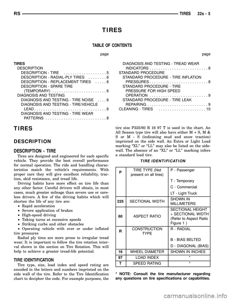
chart to decipher the code. For example purposes, the tire size P225/60 R 16 97 T is used in the chart. An
All Season type tire will also have eithe
rM+S,M&
SorM-S (indicating mud and snow traction)
imprinted on the side wall. An Extra or Light Load
marking ªXLº or ªLLº may also be listed on the side-
wall. The absence of an ªXLº or ªLLº marking infers
a standard load tire.
TIRE IDENTIFICATION
P TIRE TYPE (Not
present on all tires) P - Passenger
T - Temporary
C - Commercial
LT - Light Truck
225 SECTIONAL WIDTH SHOWN IN
MILLIMETERS
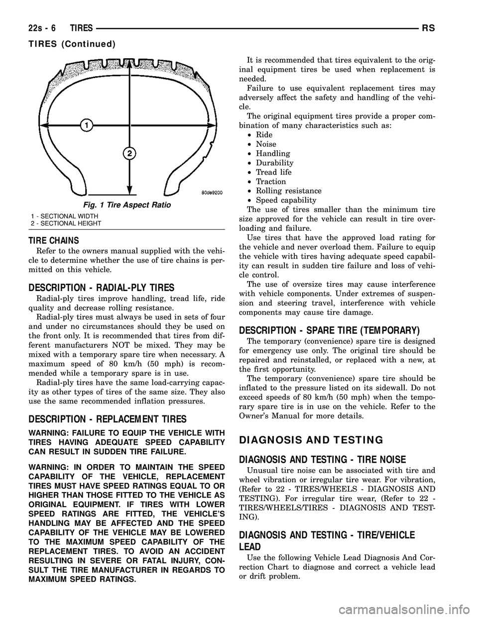
60 ASPECT RATIO SECTIONAL HEIGHT
÷ SECTIONAL WIDTH
(Refer to Aspect Ratio
Figure 1 )
R CONSTRUCTION
TYPE R - RADIAL
B - BIAS BELTED
D - DIAGONAL (BIAS)
16 WHEEL DIAMETER SHOWN IN INCHES
97 LOAD INDEX *
T SPEED RATING *
* NOTE: Consult the tire manufacturer regarding
any questions on tire specifications or capabilities.
RS TIRES22s-5
Page 2107 of 2585
TIRE CHAINS
Refer to the owners manual supplied with the vehi-
cle to determine whether the use of tire chains is per-
mitted on this vehicle.
DESCRIPTION - RADIAL-PLY TIRES
Radial-ply tires improve handling, tread life, ride
quality and decrease rolling resistance. Radial-ply tires must always be used in sets of four
and under no circumstances should they be used on
the front only. It is recommended that tires from dif-
ferent manufacturers NOT be mixed. They may be
mixed with a temporary spare tire when necessary. A
maximum speed of 80 km/h (50 mph) is recom-
mended while a temporary spare is in use. Radial-ply tires have the same load-carrying capac-
ity as other types of tires of the same size. They also
use the same recommended inflation pressures.
DESCRIPTION - REPLACEMENT TIRES
WARNING: FAILURE TO EQUIP THE VEHICLE WITH
TIRES HAVING ADEQUATE SPEED CAPABILITY
CAN RESULT IN SUDDEN TIRE FAILURE.
WARNING: IN ORDER TO MAINTAIN THE SPEED
CAPABILITY OF THE VEHICLE, REPLACEMENT
TIRES MUST HAVE SPEED RATINGS EQUAL TO OR
HIGHER THAN THOSE FITTED TO THE VEHICLE AS
ORIGINAL EQUIPMENT. IF TIRES WITH LOWER
SPEED RATINGS ARE FITTED, THE VEHICLE'S
HANDLING MAY BE AFFECTED AND THE SPEED
CAPABILITY OF THE VEHICLE MAY BE LOWERED
TO THE MAXIMUM SPEED CAPABILITY OF THE
REPLACEMENT TIRES. TO AVOID AN ACCIDENT
RESULTING IN SEVERE OR FATAL INJURY, CON-
SULT THE TIRE MANUFACTURER IN REGARDS TO
MAXIMUM SPEED RATINGS. It is recommended that tires equivalent to the orig-
inal equipment tires be used when replacement is
needed. Failure to use equivalent replacement tires may
adversely affect the safety and handling of the vehi-
cle. The original equipment tires provide a proper com-
bination of many characteristics such as: ² Ride
² Noise
² Handling
² Durability
² Tread life
² Traction
² Rolling resistance
² Speed capability
The use of tires smaller than the minimum tire
size approved for the vehicle can result in tire over-
loading and failure. Use tires that have the approved load rating for
the vehicle and never overload them. Failure to equip
the vehicle with tires having adequate speed capabil-
ity can result in sudden tire failure and loss of vehi-
cle control. The use of oversize tires may cause interference
with vehicle components. Under extremes of suspen-
sion and steering travel, interference with vehicle
components may cause tire damage.
DESCRIPTION - SPARE TIRE (TEMPORARY)
The temporary (convenience) spare tire is designed
for emergency use only. The original tire should be
repaired and reinstalled, or replaced with a new, at
the first opportunity. The temporary (convenience) spare tire should be
inflated to the pressure listed on its sidewall. Do not
exceed speeds of 80 km/h (50 mph) when the tempo-
rary spare tire is in use on the vehicle. Refer to the
Owner's Manual for more details.
DIAGNOSIS AND TESTING
DIAGNOSIS AND TESTING - TIRE NOISE
Unusual tire noise can be associated with tire and
wheel vibration or irregular tire wear. For vibration,
(Refer to 22 - TIRES/WHEELS - DIAGNOSIS AND
TESTING). For irregular tire wear, (Refer to 22 -
TIRES/WHEELS/TIRES - DIAGNOSIS AND TEST-
ING).
DIAGNOSIS AND TESTING - TIRE/VEHICLE
LEAD
Use the following Vehicle Lead Diagnosis And Cor-
rection Chart to diagnose and correct a vehicle lead
or drift problem.
Fig. 1 Tire Aspect Ratio
1 - SECTIONAL WIDTH
2 - SECTIONAL HEIGHT
22s - 6 TIRESRS
TIRES (Continued)
Page 2119 of 2585
(1) Cover waxed paper or plastic with adhesive
backed nylon mesh (dry wall tape) larger than the
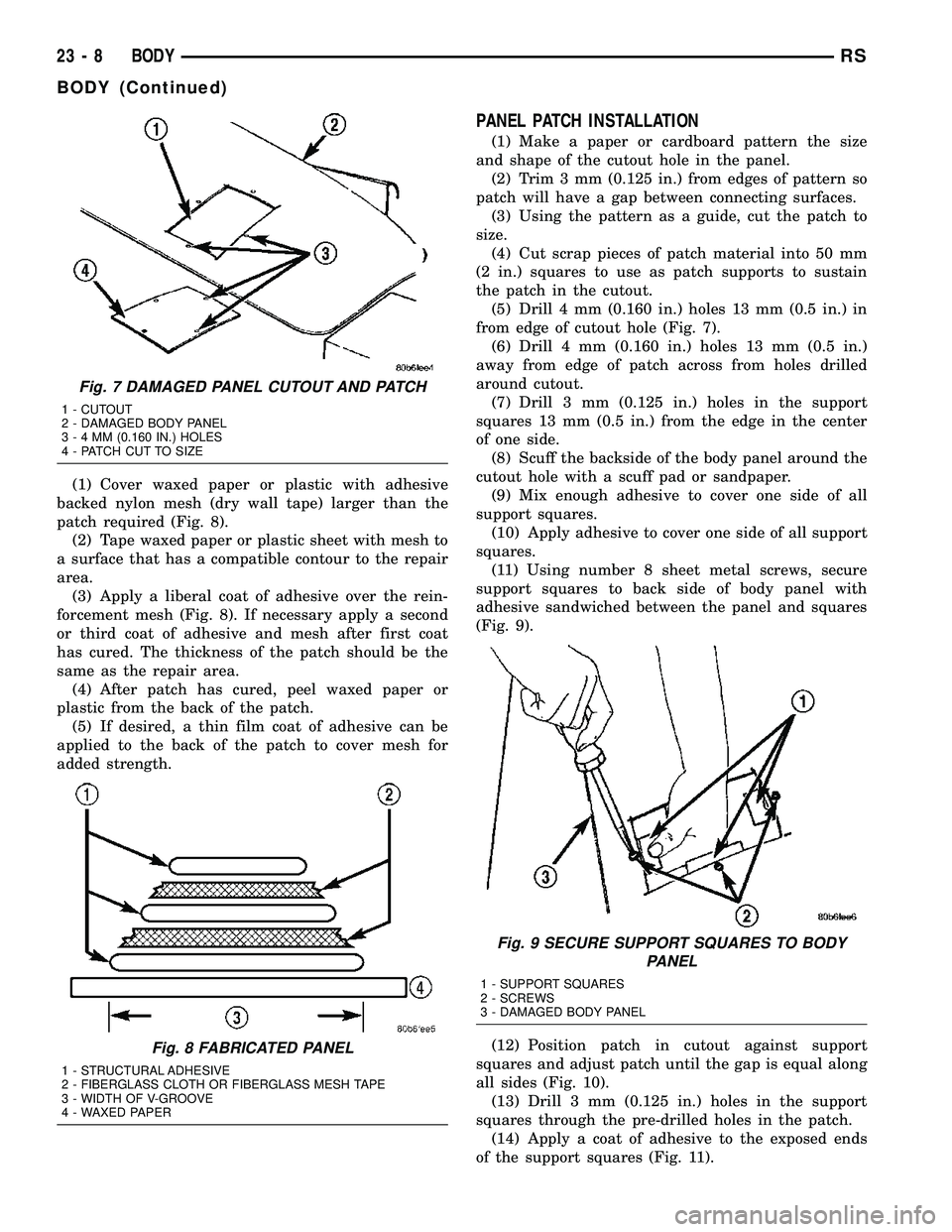
patch required (Fig. 8).
(2) Tape waxed paper or plastic sheet with mesh to
a surface that has a compatible contour to the repair
area.
(3) Apply a liberal coat of adhesive over the rein-
forcement mesh (Fig. 8). If necessary apply a second
or third coat of adhesive and mesh after first coat
has cured. The thickness of the patch should be the
same as the repair area.
(4) After patch has cured, peel waxed paper or
plastic from the back of the patch.
(5) If desired, a thin film coat of adhesive can be
applied to the back of the patch to cover mesh for
added strength.
PANEL PATCH INSTALLATION
(1) Make a paper or cardboard pattern the size
and shape of the cutout hole in the panel.
(2) Trim 3 mm (0.125 in.) from edges of pattern so
patch will have a gap between connecting surfaces.
(3) Using the pattern as a guide, cut the patch to
size.
(4) Cut scrap pieces of patch material into 50 mm
(2 in.) squares to use as patch supports to sustain
the patch in the cutout.
(5) Drill 4 mm (0.160 in.) holes 13 mm (0.5 in.) in
from edge of cutout hole (Fig. 7).
(6) Drill 4 mm (0.160 in.) holes 13 mm (0.5 in.)
away from edge of patch across from holes drilled
around cutout.
(7) Drill 3 mm (0.125 in.) holes in the support
squares 13 mm (0.5 in.) from the edge in the center
of one side.
(8) Scuff the backside of the body panel around the
cutout hole with a scuff pad or sandpaper.
(9) Mix enough adhesive to cover one side of all
support squares.
(10) Apply adhesive to cover one side of all support
squares.
(11) Using number 8 sheet metal screws, secure
support squares to back side of body panel with
adhesive sandwiched between the panel and squares
(Fig. 9).
(12) Position patch in cutout against support
squares and adjust patch until the gap is equal along
all sides (Fig. 10).
(13) Drill 3 mm (0.125 in.) holes in the support
squares through the pre-drilled holes in the patch.
(14) Apply a coat of adhesive to the exposed ends
of the support squares (Fig. 11).
Fig. 7 DAMAGED PANEL CUTOUT AND PATCH
1 - CUTOUT
2 - DAMAGED BODY PANEL
3-4MM(0.160 IN.) HOLES
4 - PATCH CUT TO SIZE
Fig. 8 FABRICATED PANEL
1 - STRUCTURAL ADHESIVE
2 - FIBERGLASS CLOTH OR FIBERGLASS MESH TAPE
3 - WIDTH OF V-GROOVE
4 - WAXED PAPER
Fig. 9 SECURE SUPPORT SQUARES TO BODY
PANEL
1 - SUPPORT SQUARES
2 - SCREWS
3 - DAMAGED BODY PANEL
23 - 8 BODYRS
BODY (Continued)
Page 2426 of 2585
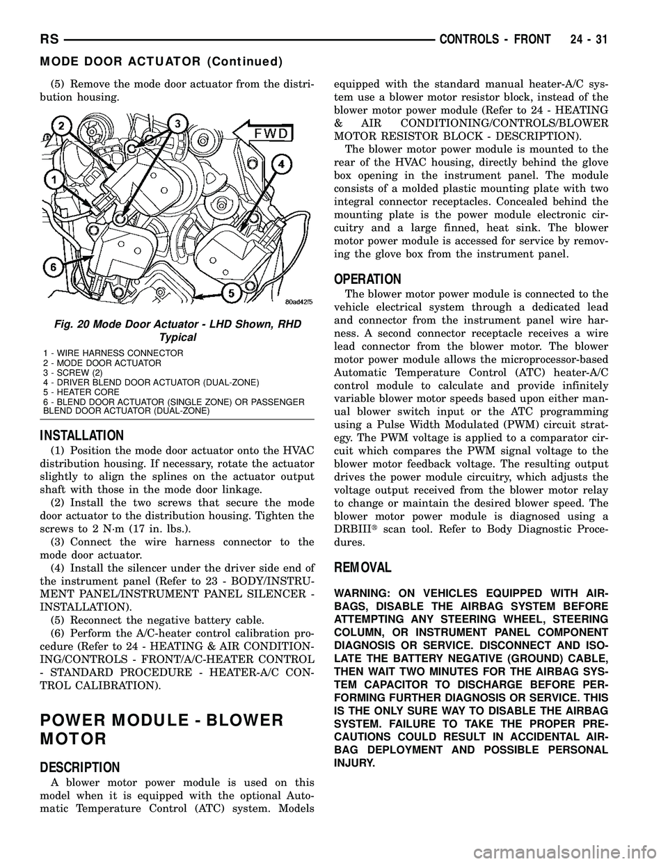
(5) Remove the mode door actuator from the distri-
bution housing.
INSTALLATION
(1) Position the mode door actuator onto the HVAC
distribution housing. If necessary, rotate the actuator
slightly to align the splines on the actuator output
shaft with those in the mode door linkage.
(2) Install the two screws that secure the mode
door actuator to the distribution housing. Tighten the
screws to 2 N´m (17 in. lbs.).
(3) Connect the wire harness connector to the
mode door actuator.
(4) Install the silencer under the driver side end of
the instrument panel (Refer to 23 - BODY/INSTRU-
MENT PANEL/INSTRUMENT PANEL SILENCER -
INSTALLATION).
(5) Reconnect the negative battery cable.
(6) Perform the A/C-heater control calibration pro-
cedure (Refer to 24 - HEATING & AIR CONDITION-
ING/CONTROLS - FRONT/A/C-HEATER CONTROL
- STANDARD PROCEDURE - HEATER-A/C CON-
TROL CALIBRATION).
POWER MODULE - BLOWER
MOTOR
DESCRIPTION
A blower motor power module is used on this
model when it is equipped with the optional Auto-
matic Temperature Control (ATC) system. Modelsequipped with the standard manual heater-A/C sys-
tem use a blower motor resistor block, instead of the
blower motor power module (Refer to 24 - HEATING
& AIR CONDITIONING/CONTROLS/BLOWER
MOTOR RESISTOR BLOCK - DESCRIPTION).
The blower motor power module is mounted to the
rear of the HVAC housing, directly behind the glove
box opening in the instrument panel. The module
consists of a molded plastic mounting plate with two
integral connector receptacles. Concealed behind the
mounting plate is the power module electronic cir-
cuitry and a large finned, heat sink. The blower
motor power module is accessed for service by remov-
ing the glove box from the instrument panel.
OPERATION
The blower motor power module is connected to the
vehicle electrical system through a dedicated lead
and connector from the instrument panel wire har-
ness. A second connector receptacle receives a wire
lead connector from the blower motor. The blower
motor power module allows the microprocessor-based
Automatic Temperature Control (ATC) heater-A/C
control module to calculate and provide infinitely
variable blower motor speeds based upon either man-
ual blower switch input or the ATC programming
using a Pulse Width Modulated (PWM) circuit strat-
egy. The PWM voltage is applied to a comparator cir-
cuit which compares the PWM signal voltage to the
blower motor feedback voltage. The resulting output
drives the power module circuitry, which adjusts the
voltage output received from the blower motor relay
to change or maintain the desired blower speed. The
blower motor power module is diagnosed using a
DRBIIItscan tool. Refer to Body Diagnostic Proce-
dures.
REMOVAL
WARNING: ON VEHICLES EQUIPPED WITH AIR-
BAGS, DISABLE THE AIRBAG SYSTEM BEFORE
ATTEMPTING ANY STEERING WHEEL, STEERING
COLUMN, OR INSTRUMENT PANEL COMPONENT
DIAGNOSIS OR SERVICE. DISCONNECT AND ISO-
LATE THE BATTERY NEGATIVE (GROUND) CABLE,
THEN WAIT TWO MINUTES FOR THE AIRBAG SYS-
TEM CAPACITOR TO DISCHARGE BEFORE PER-
FORMING FURTHER DIAGNOSIS OR SERVICE. THIS
IS THE ONLY SURE WAY TO DISABLE THE AIRBAG
SYSTEM. FAILURE TO TAKE THE PROPER PRE-
CAUTIONS COULD RESULT IN ACCIDENTAL AIR-
BAG DEPLOYMENT AND POSSIBLE PERSONAL
INJURY.
Fig. 20 Mode Door Actuator - LHD Shown, RHD
Typical
1 - WIRE HARNESS CONNECTOR
2 - MODE DOOR ACTUATOR
3 - SCREW (2)
4 - DRIVER BLEND DOOR ACTUATOR (DUAL-ZONE)
5 - HEATER CORE
6 - BLEND DOOR ACTUATOR (SINGLE ZONE) OR PASSENGER
BLEND DOOR ACTUATOR (DUAL-ZONE)
RSCONTROLS - FRONT24-31
MODE DOOR ACTUATOR (Continued)
Page 2436 of 2585
(6) Install the screw that secures the front of the
rear HVAC housing to the right quarter inner panel.
Tighten the screw to 11 N´m (97 in. lbs.).
(7) Install the screw that secures the back of the
rear HVAC housing to the right D-pillar. Tighten the
screw to 11 N´m (97 in. lbs.).
(8) Install the two screws that secure the top of
the quarter trim panel attaching bracket to the quar-
ter inner panel. Tighten the screws to 2 N´m (17 in.
lbs.).
(9) Reinstall the right quarter trim panel and
right D-pillar trim panel onto the quarter inner
panel (Refer to 23 - BODY/INTERIOR/QUARTER
TRIM PANEL - INSTALLATION).
(10) Reconnect the battery negative cable.
(11) Perform the heater-A/C control calibration
procedure (Refer to 24 - HEATING & AIR CONDI-
TIONING/CONTROLS - FRONT/A/C-HEATER CON-
TROL - STANDARD PROCEDURE - HEATER-A/C
CONTROL CALIBRATION).
POWER MODULE - REAR
BLOWER MOTOR
DESCRIPTION
A rear blower motor power module is used on this
model when it is equipped with the optional Auto-
matic Temperature Control (ATC) system. Models
equipped with the standard manual heater-A/C sys-
tem use a blower motor resistor block , instead of the
blower motor power module (Refer to 24 - HEATING
& AIR CONDITIONING/CONTROLS/BLOWER
MOTOR RESISTOR BLOCK - DESCRIPTION).
The rear blower motor power module is installed in
the back of the rear HVAC housing, directly above
the expansion valve. The module consists of a molded
plastic mounting plate with two integral connector
receptacles. Concealed behind the mounting plate
within the evaporator housing is the power module
electronic circuitry and a large finned, heat sink. The
power module is accessed for service by removing the
right quarter and D-pillar trim panels.
OPERATION
The rear blower motor power module is connected
to the vehicle electrical system through a dedicated
take out and connector of the rear HVAC wire har-
ness. A second connector receptacle receives the pig-
tail wire connector from the rear blower motor. The
rear blower motor power module allows the micropro-
cessor-based Automatic Temperature Control (ATC)
heater-A/C control module to calculate and provide
infinitely variable blower motor speeds based upon
either manual blower switch input or the ATC pro-
gramming using a Pulse Width Modulated (PWM)circuit strategy. The PWM voltage is applied to a
comparator circuit which compares the PWM signal
voltage to the blower motor feedback voltage. The
resulting output drives the power module circuitry,
which adjusts the voltage output received from the
rear blower motor relay to change or maintain the
desired blower speed. The rear blower motor power
module is diagnosed using a DRBIIItscan tool. Refer
to Body Diagnostic Procedures.
REMOVAL
(1) Disconnect and isolate the battery negative
cable.
(2) Remove the right quarter trim panel and right
D-pillar trim panel from the quarter inner panel
(Refer to 23 - BODY/INTERIOR/QUARTER TRIM
PANEL - REMOVAL).
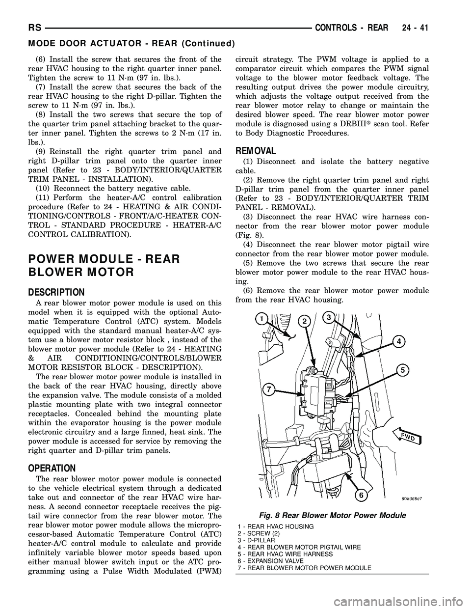
(3) Disconnect the rear HVAC wire harness con-
nector from the rear blower motor power module
(Fig. 8).
(4) Disconnect the rear blower motor pigtail wire
connector from the rear blower motor power module.
(5) Remove the two screws that secure the rear
blower motor power module to the rear HVAC hous-
ing.
(6) Remove the rear blower motor power module
from the rear HVAC housing.
Fig. 8 Rear Blower Motor Power Module
1 - REAR HVAC HOUSING
2 - SCREW (2)
3 - D-PILLAR
4 - REAR BLOWER MOTOR PIGTAIL WIRE
5 - REAR HVAC WIRE HARNESS
6 - EXPANSION VALVE
7 - REAR BLOWER MOTOR POWER MODULE
RSCONTROLS - REAR24-41
MODE DOOR ACTUATOR - REAR (Continued)
Page 2441 of 2585
(2) Engage the retainer features on the top of the
outlet housing with their receptacles at the top of the
center bezel, then roll the bottom of the outlet hous-
ing downwards towards the center bezel.
(3) Install the three screws that secure the bottom
of the outlet housing to the center bezel. Tighten the
screws to 2 N´m (17 in. lbs.).
(4) If the vehicle is equipped with the optional
ATC system, reconnect the ATC remote infrared tem-
perature sensor jumper harness to the sensor connec-
tor receptacle located on the bottom of the center
outlet housing.
(5) Reinstall the center bezel onto the instrument
panel (Refer to 23 - BODY/INSTRUMENT PANEL/
INSTRUMENT PANEL CENTER BEZEL - INSTAL-
LATION).
(6) Reconnect the battery negative cable.
INSTALLATION - DEMISTER OUTLET
(1) Position the demister outlet over the demister
duct opening in the instrument panel top pad.
(2) Using hand pressure, press the demister outlet
firmly and evenly into the instrument panel top pad
opening until the snap features on the outlet are
fully engaged.
INSTALLATION - INSTRUMENT PANEL OUTLET
(1) Position the instrument panel outlet into the
panel duct opening in the instrument panel top pad.
(2) Using hand pressure, press the instrument
panel outlet firmly and evenly into the instrument
panel top pad opening until the snap features on the
outlet are fully engaged.
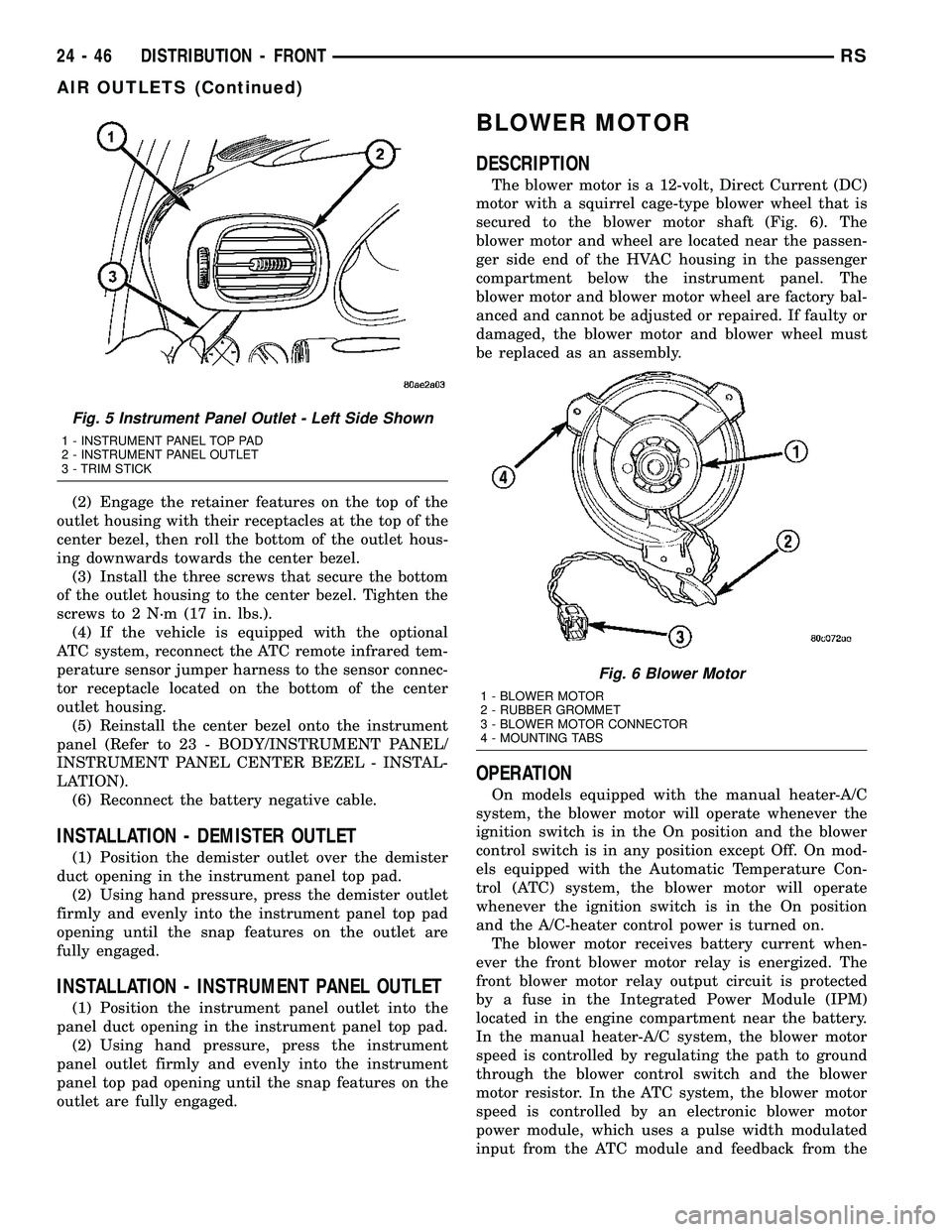
BLOWER MOTOR
DESCRIPTION
The blower motor is a 12-volt, Direct Current (DC)
motor with a squirrel cage-type blower wheel that is
secured to the blower motor shaft (Fig. 6). The
blower motor and wheel are located near the passen-
ger side end of the HVAC housing in the passenger
compartment below the instrument panel. The
blower motor and blower motor wheel are factory bal-
anced and cannot be adjusted or repaired. If faulty or
damaged, the blower motor and blower wheel must
be replaced as an assembly.
OPERATION
On models equipped with the manual heater-A/C
system, the blower motor will operate whenever the
ignition switch is in the On position and the blower
control switch is in any position except Off. On mod-
els equipped with the Automatic Temperature Con-
trol (ATC) system, the blower motor will operate
whenever the ignition switch is in the On position
and the A/C-heater control power is turned on.
The blower motor receives battery current when-
ever the front blower motor relay is energized. The
front blower motor relay output circuit is protected
by a fuse in the Integrated Power Module (IPM)
located in the engine compartment near the battery.
In the manual heater-A/C system, the blower motor
speed is controlled by regulating the path to ground
through the blower control switch and the blower
motor resistor. In the ATC system, the blower motor
speed is controlled by an electronic blower motor
power module, which uses a pulse width modulated
input from the ATC module and feedback from the
Fig. 5 Instrument Panel Outlet - Left Side Shown
1 - INSTRUMENT PANEL TOP PAD
2 - INSTRUMENT PANEL OUTLET
3 - TRIM STICK
Fig. 6 Blower Motor
1 - BLOWER MOTOR
2 - RUBBER GROMMET
3 - BLOWER MOTOR CONNECTOR
4 - MOUNTING TABS
24 - 46 DISTRIBUTION - FRONTRS
AIR OUTLETS (Continued)
Page 2452 of 2585
DISTRIBUTION DUCT
REMOVAL
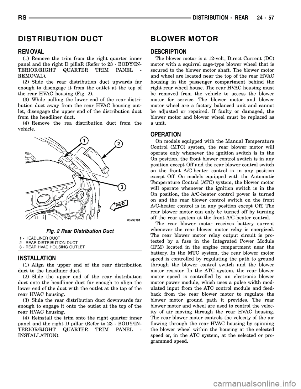
(1) Remove the trim from the right quarter inner
panel and the right D pillaR (Refer to 23 - BODY/IN-
TERIOR/RIGHT QUARTER TRIM PANEL -
REMOVAL).
(2) Slide the rear distribution duct upwards far
enough to disengage it from the outlet at the top of
the rear HVAC housing (Fig. 2).
(3) While pulling the lower end of the rear distri-
bution duct away from the rear HVAC housing out-
let, disengage the upper end of the distribution duct
from the headliner duct.
(4) Remove the rea distribution duct from the
vehicle.
INSTALLATION
(1) Align the upper end of the rear distribution
duct to the headliner duct.
(2) Slide the upper end of the rear distribution
duct onto the headliner duct far enough to align the
lower end of the duct with the outlet at the top of the
rear HVAC housing.
(3) Slide the rear distribution duct downwards far
enough to engage it onto the outlet at the top of the
rear HVAC housing.
(4) Reinstall the trim onto the right quarter inner
panel and the right D pillar (Refer to 23 - BODY/IN-
TERIOR/RIGHT QUARTER TRIM PANEL -
INSTALLATION).
BLOWER MOTOR
DESCRIPTION
The blower motor is a 12-volt, Direct Current (DC)
motor with a squirrel cage-type blower wheel that is
secured to the blower motor shaft. The blower motor
and wheel are located near the top of the rear HVAC
housing in the passenger compartment behind the
right rear wheel house. The rear HVAC housing must
be removed from the vehicle to access the blower
motor for service. The blower motor and blower
motor wheel are a factory balanced unit and cannot
be adjusted or repaired. If faulty or damaged, the
blower motor and blower wheel must be replaced as
a unit.
OPERATION
On models equipped with the Manual Temperature
Control (MTC) system, the rear blower motor will
operate only whenever the ignition switch is in the
On position, the front blower control switch is in any
position except Off and the rear blower control switch
on the front A/C-heater control is in any position
except Off. On models equipped with the Automatic
Temperature Control (ATC) system, the blower motor
will operate whenever the ignition switch is in the
On position, the A/C-heater control power is turned
on and the rear blower control switch on the front
A/C-heater control is in any position except Off. The
rear blower motor can only be turned off by turning
off the rear system at the front A/C-heater control.
The rear blower motor receives battery current
whenever the rear blower motor relay is energized.
The rear blower motor relay output circuit is pro-
tected by a fuse in the Integrated Power Module
(IPM) located in the engine compartment near the
battery. In the MTC system, the rear blower motor
speed is controlled by regulating the path to ground
through the blower control switch and the blower
motor resistor. In the ATC system, the rear blower
motor speed is controlled by an electronic blower
motor power module, which uses a pulse width mod-
ulated input from the ATC control module and feed-
back from the rear blower motor to regulate the
blower motor ground path it provides. The rear
blower motor and wheel are used to control the veloc-
ity of air moving through the rear HVAC housing.
The rear blower motor controls the velocity of the air
flowing through the rear HVAC housing by spinning
the blower wheel within the housing at the selected
speed or, in the ATC system, at the selected or pro-
grammed speed.
Fig. 2 Rear Distribution Duct
1 - HEADLINER DUCT
2 - REAR DISTRIBUTION DUCT
3 - REAR HVAC HOUSING OUTLET
RSDISTRIBUTION - REAR24-57