2004 CHRYSLER VOYAGER Temperature
[x] Cancel search: TemperaturePage 1889 of 2585
The process of elimination can be used to detect
any unit which slips and to confirm proper operation
of good units. Road test analysis can diagnose slip-
ping units, but the cause of the malfunction cannot
be determined. Practically any condition can be
caused by leaking hydraulic circuits or sticking
valves.
DIAGNOSIS AND TESTING - HYDRAULIC
PRESSURE TESTS
Pressure testing is a very important step in the
diagnostic procedure. These tests usually reveal the
cause of most hydraulic transaxle problems. Before performing pressure tests, be certain that
fluid level and condition, and shift cable adjustments
have been checked and approved. Fluid must be at
operating temperature (150 to 200 degrees F.). Install an engine tachometer, raise vehicle on hoist
which allows front wheels to turn, and position
tachometer so it can be read. Attach 300 psi gauge (C-3293SP) to port(s)
required for test(s) being conducted. Use adapter set
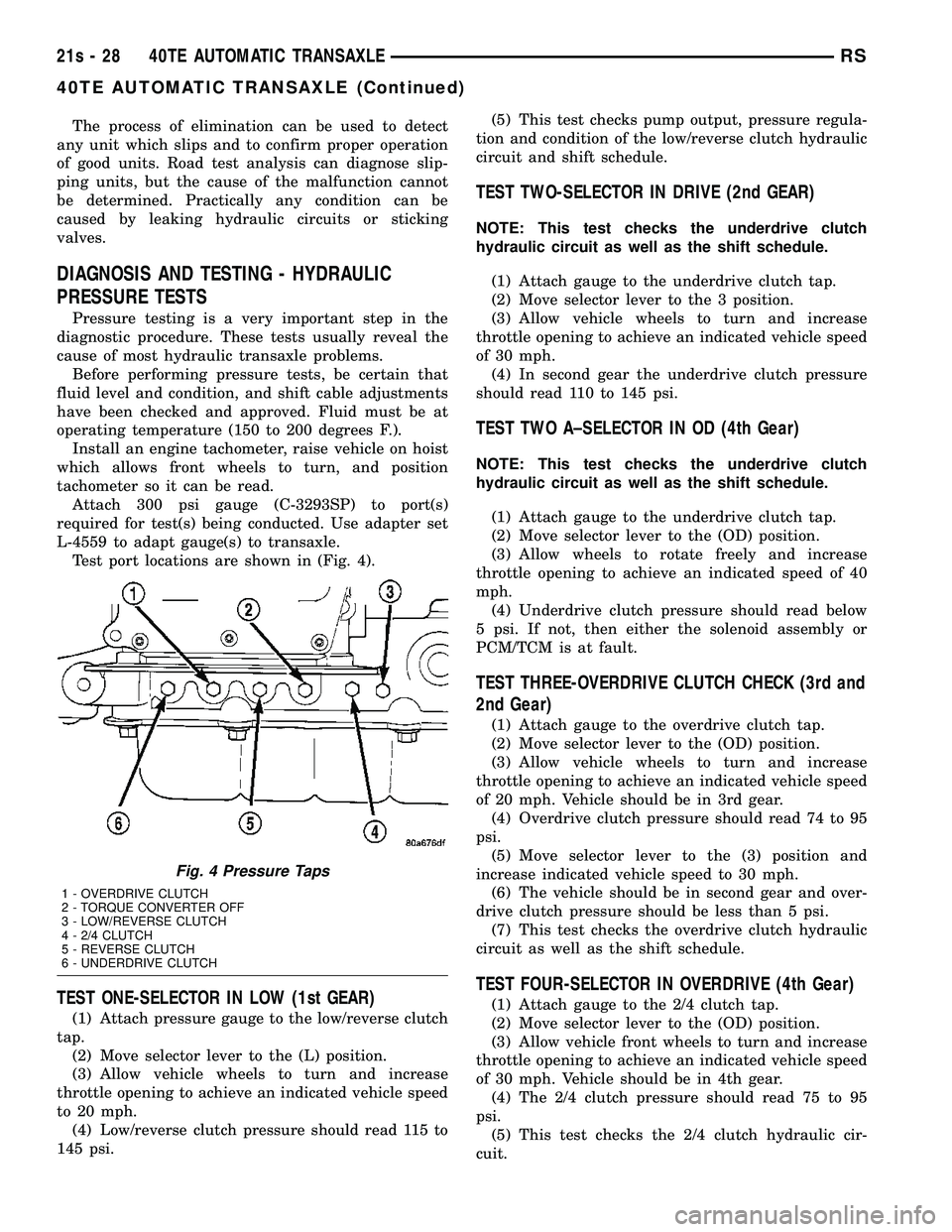
L-4559 to adapt gauge(s) to transaxle. Test port locations are shown in (Fig. 4).
TEST ONE-SELECTOR IN LOW (1st GEAR)
(1) Attach pressure gauge to the low/reverse clutch
tap. (2) Move selector lever to the (L) position.
(3) Allow vehicle wheels to turn and increase
throttle opening to achieve an indicated vehicle speed
to 20 mph. (4) Low/reverse clutch pressure should read 115 to
145 psi. (5) This test checks pump output, pressure regula-
tion and condition of the low/reverse clutch hydraulic
circuit and shift schedule.
TEST TWO-SELECTOR IN DRIVE (2nd GEAR)
NOTE: This test checks the underdrive clutch
hydraulic circuit as well as the shift schedule.
(1) Attach gauge to the underdrive clutch tap.
(2) Move selector lever to the 3 position.
(3) Allow vehicle wheels to turn and increase
throttle opening to achieve an indicated vehicle speed
of 30 mph. (4) In second gear the underdrive clutch pressure
should read 110 to 145 psi.
TEST TWO A±SELECTOR IN OD (4th Gear)
NOTE: This test checks the underdrive clutch
hydraulic circuit as well as the shift schedule.
(1) Attach gauge to the underdrive clutch tap.
(2) Move selector lever to the (OD) position.
(3) Allow wheels to rotate freely and increase
throttle opening to achieve an indicated speed of 40
mph. (4) Underdrive clutch pressure should read below
5 psi. If not, then either the solenoid assembly or
PCM/TCM is at fault.
TEST THREE-OVERDRIVE CLUTCH CHECK (3rd and
2nd Gear)
(1) Attach gauge to the overdrive clutch tap.
(2) Move selector lever to the (OD) position.
(3) Allow vehicle wheels to turn and increase
throttle opening to achieve an indicated vehicle speed
of 20 mph. Vehicle should be in 3rd gear. (4) Overdrive clutch pressure should read 74 to 95
psi. (5) Move selector lever to the (3) position and
increase indicated vehicle speed to 30 mph. (6) The vehicle should be in second gear and over-
drive clutch pressure should be less than 5 psi. (7) This test checks the overdrive clutch hydraulic
circuit as well as the shift schedule.
TEST FOUR-SELECTOR IN OVERDRIVE (4th Gear)
(1) Attach gauge to the 2/4 clutch tap.
(2) Move selector lever to the (OD) position.
(3) Allow vehicle front wheels to turn and increase
throttle opening to achieve an indicated vehicle speed
of 30 mph. Vehicle should be in 4th gear. (4) The 2/4 clutch pressure should read 75 to 95
psi. (5) This test checks the 2/4 clutch hydraulic cir-
cuit.
Fig. 4 Pressure Taps
1 - OVERDRIVE CLUTCH
2 - TORQUE CONVERTER OFF
3 - LOW/REVERSE CLUTCH
4 - 2/4 CLUTCH
5 - REVERSE CLUTCH
6 - UNDERDRIVE CLUTCH
21s - 28 40TE AUTOMATIC TRANSAXLERS
40TE AUTOMATIC TRANSAXLE (Continued)
Page 1963 of 2585
PRELOAD ADJUSTMENT W/O SHIM(1) Remove the bearing cup from the differential
bearing retainer using Miller special Tool 6062A. (2) Remove existing shim from under bearing cup.
(3) Reinstall the bearing cup into the retainer
using Miller Special Tool 6061, and C-4171.
NOTE: Oil baffle is not required when making the
shim calculation.
(4) Install the bearing retainer into the case.
Torque bolts to 28 N ²m (250 in. lbs.).
(5) Position the transaxle assembly vertically on
the support stand and install Miller Special Tool
L-4436-A into the bearing retainer. (6) Rotate the differential at least one full revolu-
tion to ensure the tapered roller bearings are fully
seated. (7) Attach a dial indicator to the case and zero the
dial. Place the tip on the end of Special Tool
L-4436-A. (8) Place a large screwdriver to each side of the
ring gear and lift. Check the dial indicator for the
amount of end play.
CAUTION: Do not damage the transaxle case and/or
differential retainer sealing surface.
(9) Using the end play measurement that was
determined, add 0.18mm (0.007 inch). This should
give you between 5 and 18 inch pounds of bearing
preload. Refer to the Differential Bearing Shim Chart
to determine which shim to use. (10) Remove the differential bearing retainer.
Remove the bearing cup. (11) Install the oil baffle. Install the proper shim
combination under the bearing cup. (12) Install the differential bearing retainer. Seal
the retainer to the housing with Mopar tSilicone
Rubber Adhesive Sealant. Torque bolts to 28 N ²m
(250 in. lbs.). (13) Using Miller Special Tool L-4436-A and an
inch-pound torque wrench, check the turning torque
of the differential (Fig. 186). The turning torque
should be between 5-18 inch-pounds.
NOTE: If turning torque is too high install a 0.05mm
(0.002 inch) thicker shim. If the turning torque is too
low, install a 0.05mm (0.002 inch) thinner shim.
Repeat until 5-18 inch-pounds of turning torque is
obtained.FLUID
STANDARD PROCEDURE
FLUID LEVEL AND CONDITION CHECK
NOTE: Only transmission fluid of the type labeled
Mopar ATF+4 (Automatic Transmission Fluid)
should be used in this transaxle.
FLUID LEVEL CHECK
The transmission sump has a fluid level indicator
(dipstick) to check oil similar to most automatic
transmissions. It is located on the left side of the
engine. Be sure to wipe all dirt from dipstick handle
before removing. The torque converter fills in both the P Park and N
Neutral positions. Place the selector lever in P Park
to be sure that the fluid level check is accurate. The
engine should be running at idle speed for at
least one minute, with the vehicle on level
ground. At normal operating temperature 82É C
(180É F), the fluid level is correct if it is in the HOT
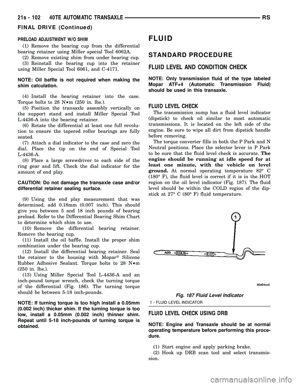
region on the oil level indicator (Fig. 187). The fluid
level should be within the COLD region of the dip-
stick at 27É C (80É F) fluid temperature.
FLUID LEVEL CHECK USING DRB
NOTE: Engine and Transaxle should be at normal
operating temperature before performing this proce-
dure.
(1) Start engine and apply parking brake.
(2) Hook up DRB scan tool and select transmis-
sion.
Fig. 187 Fluid Level Indicator
1 - FLUID LEVEL INDICATOR
21s - 102 40TE AUTOMATIC TRANSAXLERS
FINAL DRIVE (Continued)
Page 1964 of 2585
(3) Select sensors.
(4) Read the transmission temperature value.
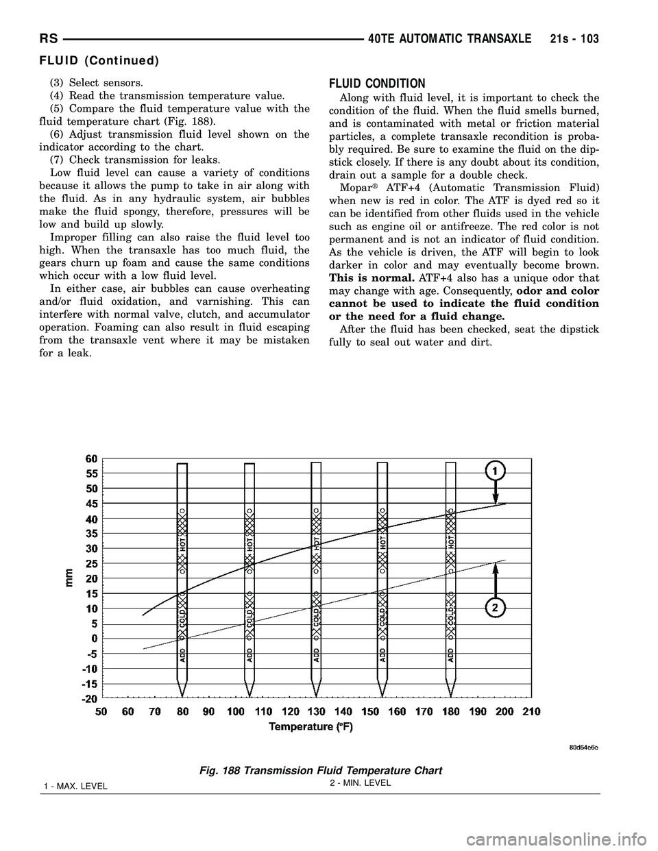
(5) Compare the fluid temperature value with the
fluid temperature chart (Fig. 188). (6) Adjust transmission fluid level shown on the
indicator according to the chart. (7) Check transmission for leaks.
Low fluid level can cause a variety of conditions
because it allows the pump to take in air along with
the fluid. As in any hydraulic system, air bubbles
make the fluid spongy, therefore, pressures will be
low and build up slowly. Improper filling can also raise the fluid level too
high. When the transaxle has too much fluid, the
gears churn up foam and cause the same conditions
which occur with a low fluid level. In either case, air bubbles can cause overheating
and/or fluid oxidation, and varnishing. This can
interfere with normal valve, clutch, and accumulator
operation. Foaming can also result in fluid escaping
from the transaxle vent where it may be mistaken
for a leak.FLUID CONDITION
Along with fluid level, it is important to check the
condition of the fluid. When the fluid smells burned,
and is contaminated with metal or friction material
particles, a complete transaxle recondition is proba-
bly required. Be sure to examine the fluid on the dip-
stick closely. If there is any doubt about its condition,
drain out a sample for a double check. Mopar tATF+4 (Automatic Transmission Fluid)
when new is red in color. The ATF is dyed red so it
can be identified from other fluids used in the vehicle
such as engine oil or antifreeze. The red color is not
permanent and is not an indicator of fluid condition.
As the vehicle is driven, the ATF will begin to look
darker in color and may eventually become brown.
This is normal. ATF+4 also has a unique odor that
may change with age. Consequently, odor and color
cannot be used to indicate the fluid condition
or the need for a fluid change. After the fluid has been checked, seat the dipstick
fully to seal out water and dirt.
Fig. 188 Transmission Fluid Temperature Chart
1 - MAX. LEVEL 2 - MIN. LEVEL
RS
40TE AUTOMATIC TRANSAXLE21s - 103
FLUID (Continued)
Page 1965 of 2585

STANDARD PROCEDURE - FLUID AND FILTER
SERVICE
NOTE: Refer to the maintenance schedules in
LUBRICATION and MAINTENANCE, or the vehicle
owner's manual, for the recommended maintenance
(fluid/filter change) intervals for this transaxle.
NOTE: Only fluids of the type labeled MoparTATF+4
should be used. A filter change should be made at
the time of the transmission oil change. The magnet
(on the inside of the oil pan) should also be cleaned
with a clean, dry cloth.
NOTE: If the transaxle is disassembled for any rea-
son, the fluid and filter should be changed.
FLUID/FILTER SERVICE (RECOMMENDED)
(1) Raise vehicle on a hoist. Refer to LUBRICA-
TION and MAINTENANCE for proper procedures.
Place a drain container with a large opening, under
transaxle oil pan. (2) Remove both engine mount-to-engine cross-
member cradle nuts. Using suitable screw jack and
wood block, raise engine and transmission slightly to
facilitate transaxle oil pan removal and installation. (3) Loosen pan bolts and tap the pan at one corner
to break it loose allowing fluid to drain, then remove
the oil pan. (4) Install a new filter and o-ring on bottom of the
valve body (Fig. 189). (5) Clean the oil pan and magnet. Reinstall pan
using new Mopar Silicone Adhesive sealant. Tighten
oil pan bolts to 19 N´m (165 in. lbs.). (6) Pour four quarts of Mopar tATF+4 through the
dipstick opening. (7) Start engine and allow to idle for at least one
minute. Then, with parking and service brakes
applied, move selector lever momentarily to each
position, ending in the park or neutral position. (8) Check the transaxle fluid level and add an
appropriate amount to bring the transaxle fluid level
to 3mm (1/8 in.) below the lowest mark on the dip-
stick (Fig. 190).
(9) Recheck the fluid level after the transaxle has
reached normal operating temperature (180ÉF.). Refer
to Fluid Level and Condition Check for the proper
fluid fill procedure. (10) To prevent dirt from entering transaxle, make
certain that dipstick is fully seated into the dipstick
opening.
DIPSTICK TUBE FLUID SUCTION METHOD
(ALTERNATIVE)
(1) When performing the fluid suction method,
make sure the transaxle is at full operating temper-
ature. (2) To perform the dipstick tube fluid suction
method, use a suitable fluid suction device (VaculaŸ
or equivalent). (3) Insert the fluid suction line into the dipstick
tube.
NOTE: Verify that the suction line is inserted to the
lowest point of the transaxle oil pan. This will
ensure complete evacuation of the fluid in the pan.
(4) Follow the manufacturers recommended proce-
dure and evacuate the fluid from the transaxle.
Fig. 189 Filter and O-Ring
1 - OIL FILTER
2 - O-RING
Fig. 190 Fluid Level Indicator
1 - FLUID LEVEL INDICATOR
21s - 104 40TE AUTOMATIC TRANSAXLERS
FLUID (Continued)
Page 1966 of 2585
(5) Remove the suction line from the dipstick tube.
(6) Pour four quarts of MopartATF+4 through the
dipstick opening. (7) Start engine and allow to idle for at least one
minute. Then, with parking and service brakes
applied, move selector lever momentarily to each
position, ending in the park or neutral position. (8) Check the transaxle fluid level and add an
appropriate amount to bring the transaxle fluid level
to 3mm (1/8 in.) below the lowest mark on the dip-
stick (Fig. 190). (9) Recheck the fluid level after the transaxle has
reached normal operating temperature (180ÉF.).
(Refer to 21 - TRANSMISSION/TRANSAXLE/AUTO-
MATIC - 41TE/FLUID - STANDARD PROCEDURE) (10) To prevent dirt from entering transaxle, make
certain that dipstick is fully seated into the dipstick
opening.
GEAR SHIFT CABLE
REMOVAL
(1) Disconnect battery cables.
(2) Remove battery shield.
(3) Remove battery.
(4) Remove speed control servo and position out of
way. (5) Disconnect gear shift cable at manual valve
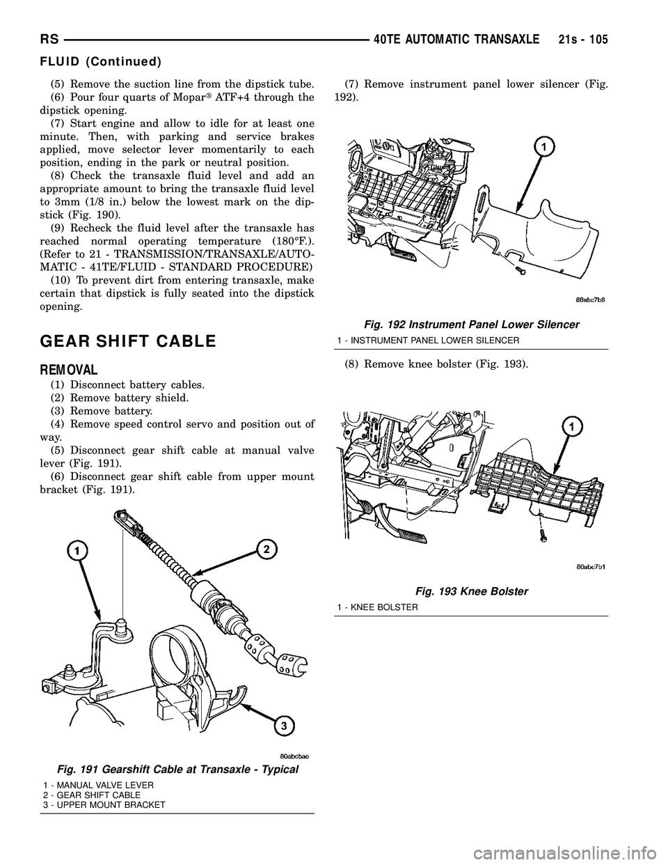
lever (Fig. 191). (6) Disconnect gear shift cable from upper mount
bracket (Fig. 191). (7) Remove instrument panel lower silencer (Fig.
192).
(8) Remove knee bolster (Fig. 193).
Fig. 191 Gearshift Cable at Transaxle - Typical
1 - MANUAL VALVE LEVER
2 - GEAR SHIFT CABLE
3 - UPPER MOUNT BRACKET
Fig. 192 Instrument Panel Lower Silencer
1 - INSTRUMENT PANEL LOWER SILENCER
Fig. 193 Knee Bolster
1 - KNEE BOLSTER
RS 40TE AUTOMATIC TRANSAXLE21s - 105
FLUID (Continued)
Page 2005 of 2585
TORQUE CONVERTER
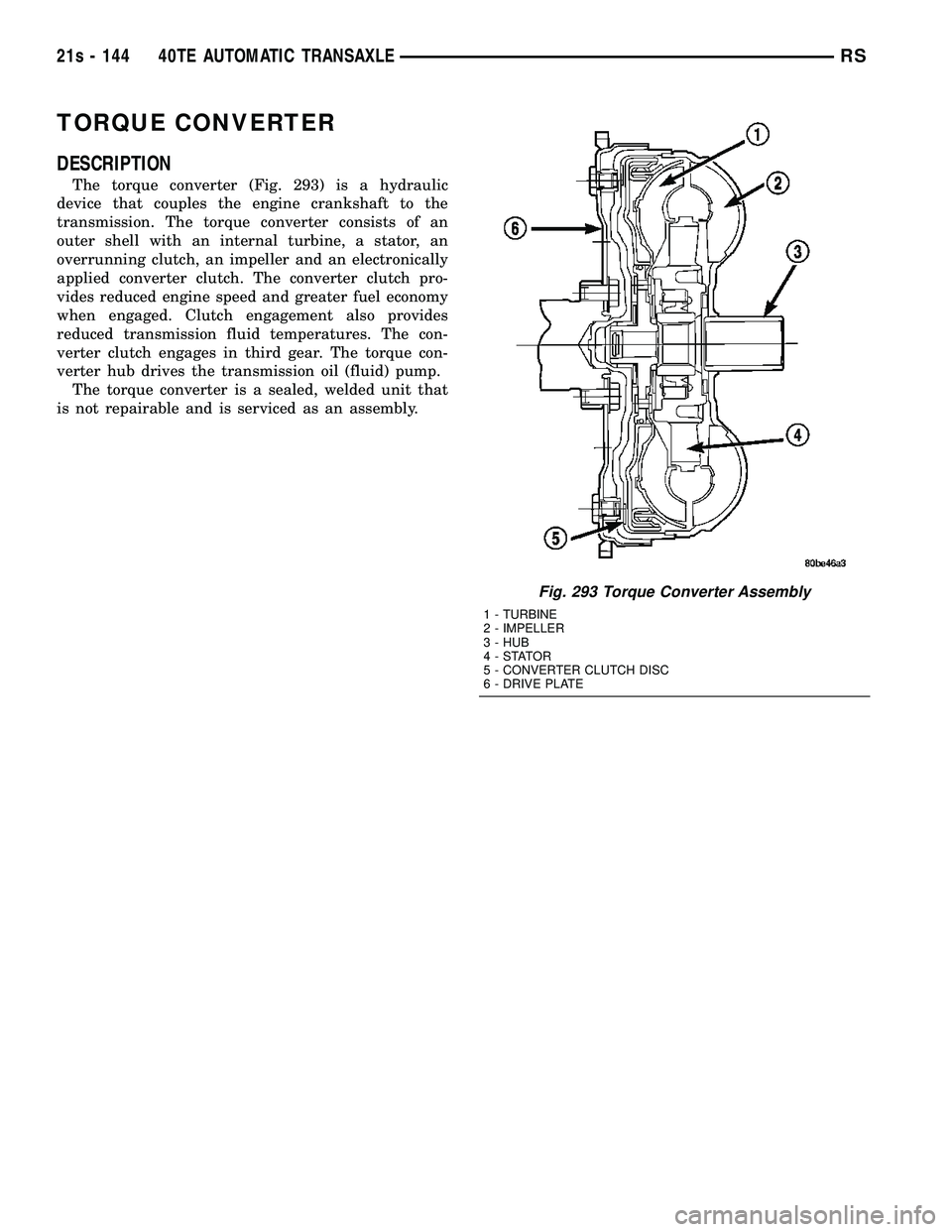
DESCRIPTION
The torque converter (Fig. 293) is a hydraulic
device that couples the engine crankshaft to the
transmission. The torque converter consists of an
outer shell with an internal turbine, a stator, an
overrunning clutch, an impeller and an electronically
applied converter clutch. The converter clutch pro-
vides reduced engine speed and greater fuel economy
when engaged. Clutch engagement also provides
reduced transmission fluid temperatures. The con-
verter clutch engages in third gear. The torque con-
verter hub drives the transmission oil (fluid) pump. The torque converter is a sealed, welded unit that
is not repairable and is serviced as an assembly.
Fig. 293 Torque Converter Assembly
1 - TURBINE
2 - IMPELLER
3 - HUB
4-STATOR
5 - CONVERTER CLUTCH DISC
6 - DRIVE PLATE
21s - 144 40TE AUTOMATIC TRANSAXLERS
Page 2010 of 2585
STATOR
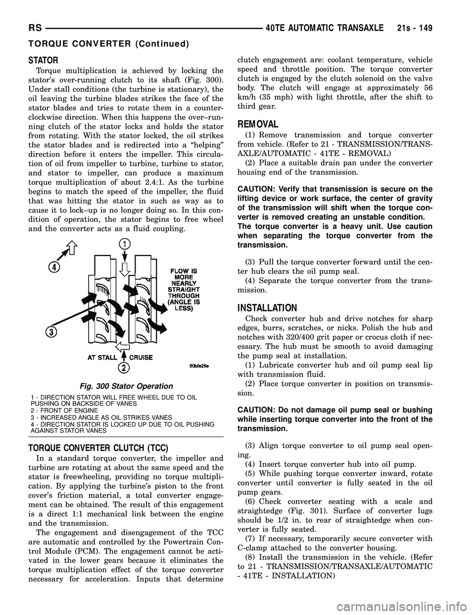
Torque multiplication is achieved by locking the
stator's over-running clutch to its shaft (Fig. 300).
Under stall conditions (the turbine is stationary), the
oil leaving the turbine blades strikes the face of the
stator blades and tries to rotate them in a counter-
clockwise direction. When this happens the over±run-
ning clutch of the stator locks and holds the stator
from rotating. With the stator locked, the oil strikes
the stator blades and is redirected into a ªhelpingº
direction before it enters the impeller. This circula-
tion of oil from impeller to turbine, turbine to stator,
and stator to impeller, can produce a maximum
torque multiplication of about 2.4:1. As the turbine
begins to match the speed of the impeller, the fluid
that was hitting the stator in such as way as to
cause it to lock±up is no longer doing so. In this con-
dition of operation, the stator begins to free wheel
and the converter acts as a fluid coupling.
TORQUE CONVERTER CLUTCH (TCC)
In a standard torque converter, the impeller and
turbine are rotating at about the same speed and the
stator is freewheeling, providing no torque multipli-
cation. By applying the turbine's piston to the front
cover's friction material, a total converter engage-
ment can be obtained. The result of this engagement
is a direct 1:1 mechanical link between the engine
and the transmission. The engagement and disengagement of the TCC
are automatic and controlled by the Powertrain Con-
trol Module (PCM). The engagement cannot be acti-
vated in the lower gears because it eliminates the
torque multiplication effect of the torque converter
necessary for acceleration. Inputs that determine clutch engagement are: coolant temperature, vehicle
speed and throttle position. The torque converter
clutch is engaged by the clutch solenoid on the valve
body. The clutch will engage at approximately 56
km/h (35 mph) with light throttle, after the shift to
third gear.
REMOVAL
(1) Remove transmission and torque converter
from vehicle. (Refer to 21 - TRANSMISSION/TRANS-
AXLE/AUTOMATIC - 41TE - REMOVAL) (2) Place a suitable drain pan under the converter
housing end of the transmission.
CAUTION: Verify that transmission is secure on the
lifting device or work surface, the center of gravity
of the transmission will shift when the torque con-
verter is removed creating an unstable condition.
The torque converter is a heavy unit. Use caution
when separating the torque converter from the
transmission.
(3) Pull the torque converter forward until the cen-
ter hub clears the oil pump seal. (4) Separate the torque converter from the trans-
mission.
INSTALLATION
Check converter hub and drive notches for sharp
edges, burrs, scratches, or nicks. Polish the hub and
notches with 320/400 grit paper or crocus cloth if nec-
essary. The hub must be smooth to avoid damaging
the pump seal at installation. (1) Lubricate converter hub and oil pump seal lip
with transmission fluid. (2) Place torque converter in position on transmis-
sion.
CAUTION: Do not damage oil pump seal or bushing
while inserting torque converter into the front of the
transmission.
(3) Align torque converter to oil pump seal open-
ing. (4) Insert torque converter hub into oil pump.
(5) While pushing torque converter inward, rotate
converter until converter is fully seated in the oil
pump gears. (6) Check converter seating with a scale and
straightedge (Fig. 301). Surface of converter lugs
should be 1/2 in. to rear of straightedge when con-
verter is fully seated. (7) If necessary, temporarily secure converter with
C-clamp attached to the converter housing. (8) Install the transmission in the vehicle. (Refer
to 21 - TRANSMISSION/TRANSAXLE/AUTOMATIC
- 41TE - INSTALLATION)
Fig. 300 Stator Operation
1 - DIRECTION STATOR WILL FREE WHEEL DUE TO OIL
PUSHING ON BACKSIDE OF VANES
2 - FRONT OF ENGINE
3 - INCREASED ANGLE AS OIL STRIKES VANES
4 - DIRECTION STATOR IS LOCKED UP DUE TO OIL PUSHING
AGAINST STATOR VANES
RS 40TE AUTOMATIC TRANSAXLE21s - 149
TORQUE CONVERTER (Continued)
Page 2012 of 2585
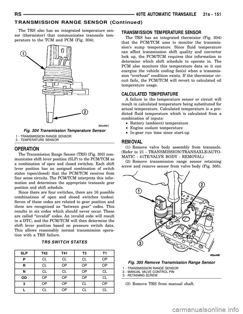
The TRS also has an integrated temperature sen-
sor (thermistor) that communicates transaxle tem-
perature to the TCM and PCM (Fig. 304).
OPERATION
The Transmission Range Sensor (TRS) (Fig. 303) com-
municates shift lever position (SLP) to the PCM/TCM as
a combination of open and closed switches. Each shift
lever position has an assigned combination of switch
states (open/closed) that the PCM/TCM receives from
four sense circuits. The PCM/TCM interprets this infor-
mation and determines the appropriate transaxle gear
position and shift schedule.
Since there are four switches, there are 16 possible
combinations of open and closed switches (codes).
Seven of these codes are related to gear position and
three are recognized as ªbetween gearº codes. This
results in six codes which should never occur. These
are called ªinvalidº codes. An invalid code will result
in a DTC, and the PCM/TCM will then determine the
shift lever position based on pressure switch data.
This allows reasonably normal transmission opera-
tion with a TRS failure.
TRS SWITCH STATES
SLP T42 T41 T3 T1
P CL CL CL OP
R CL OP OP OP
N CL CL OP CL
OD OP OP OP CL
3 OP OP CL OP
L CL OP CL CL
TRANSMISSION TEMPERATURE SENSOR
The TRS has an integrated thermistor (Fig. 304)
that the PCM/TCM uses to monitor the transmis-
sion's sump temperature. Since fluid temperature
can affect transmission shift quality and convertor
lock up, the PCM/TCM requires this information to
determine which shift schedule to operate in. The
PCM also monitors this temperature data so it can
energize the vehicle cooling fan(s) when a transmis-
sion ªoverheatº condition exists. If the thermistor cir-
cuit fails, the PCM/TCM will revert to calculated oil
temperature usage.
CALCULATED TEMPERATURE
A failure in the temperature sensor or circuit will
result in calculated temperature being substituted for
actual temperature. Calculated temperature is a pre-
dicted fluid temperature which is calculated from a
combination of inputs: ² Battery (ambient) temperature
² Engine coolant temperature
² In-gear run time since start-up
REMOVAL
(1) Remove valve body assembly from transaxle.
(Refer to 21 - TRANSMISSION/TRANSAXLE/AUTO-
MATIC - 41TE/VALVE BODY - REMOVAL) (2) Remove transmission range sensor retaining
screw and remove sensor from valve body (Fig. 305).
(3) Remove TRS from manual shaft.
Fig. 304 Transmission Temperature Sensor
1 - TRANSMISSION RANGE SENSOR
2 - TEMPERATURE SENSOR
Fig. 305 Remove Transmission Range Sensor
1 - TRANSMISSION RANGE SENSOR
2 - MANUAL VALVE CONTROL PIN
3 - RETAINING SCREW
RS 40TE AUTOMATIC TRANSAXLE21s - 151
TRANSMISSION RANGE SENSOR (Continued)