Page 1589 of 2585

FLUID
STANDARD PROCEDURE - POWER STEERING
FLUID LEVEL CHECKING
WARNING: FLUID LEVEL SHOULD BE CHECKED
WITH THE ENGINE OFF TO PREVENT INJURY
FROM MOVING PARTS AND TO ENSURE ACCU-
RATE FLUID LEVEL READING.
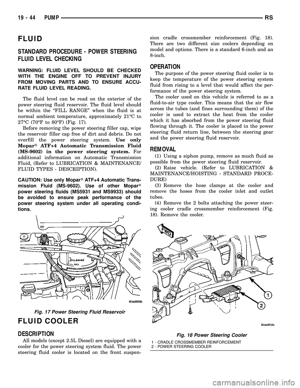
The fluid level can be read on the exterior of the
power steering fluid reservoir. The fluid level should
be within the ªFILL RANGEº when the fluid is at
normal ambient temperature, approximately 21ÉC to
27ÉC (70ÉF to 80ÉF) (Fig. 17).
Before removing the power steering filler cap, wipe
the reservoir filler cap free of dirt and debris. Do not
overfill the power steering system.Use only
MopartATF+4 Automatic Transmission Fluid
(MS-9602) in the power steering system.For
additional information on Automatic Transmission
Fluid, (Refer to LUBRICATION & MAINTENANCE/
FLUID TYPES - DESCRIPTION).
CAUTION: Use only MoparTATF+4 Automatic Trans-
mission Fluid (MS-9602). Use of other MoparT
power steering fluids (MS5931 and MS9933) should
be avoided to ensure peak performance of the
power steering system under all operating condi-
tions.
FLUID COOLER
DESCRIPTION
All models (except 2.5L Diesel) are equipped with a
cooler for the power steering system fluid. The power
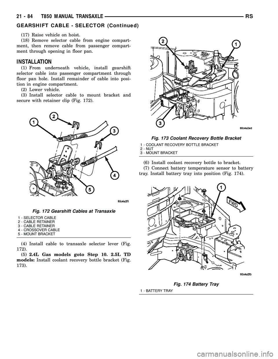
steering fluid cooler is located on the front suspen-sion cradle crossmember reinforcement (Fig. 18).
There are two different size coolers depending on
model and options. There is a standard 6-inch and an
8-inch.
OPERATION
The purpose of the power steering fluid cooler is to
keep the temperature of the power steering system
fluid from rising to a level that would affect the per-
formance of the power steering system.
The cooler used on this vehicle is referred to as a
fluid-to-air type cooler. This means that the air flow
across the tubes (and fines surrounding them) of the
cooler is used to extract the heat from the cooler
which it has absorbed from the power steering fluid
flowing through it. The cooler is placed in the power
steering fluid return line, between the steering gear
and the power steering fluid reservoir.
REMOVAL
(1) Using a siphon pump, remove as much fluid as
possible from the power steering fluid reservoir.
(2) Raise vehicle. (Refer to LUBRICATION &
MAINTENANCE/HOISTING - STANDARD PROCE-
DURE)
(3) Remove the hose clamps at the cooler and
remove the hoses from the cooler inlet and outlet
tubes.
(4) Remove the 2 bolts attaching the power steer-
ing cooler cradle crossmember reinforcement (Fig.
18). Remove the cooler.
Fig. 17 Power Steering Fluid Reservoir
Fig. 18 Power Steering Cooler
1 - CRADLE CROSSMEMBER REINFORCEMENT
2 - POWER STEERING COOLER
19 - 44 PUMPRS
Page 1630 of 2585
REMOVAL - 2.5L TD
(1) Raise hood.
(2) Disconnect both battery cables.
(3) Remove battery thermal shield (Fig. 15).
(4) Remove battery hold down bolt, clamp, and
battery (Fig. 16).(5) Remove battery tray (Fig. 17). Disconnect bat-
tery temperature sensor.
(6) Remove coolant recovery bottle from bracket.
(7) Remove coolant recovery bottle mounting
bracket (Fig. 18).
(8) Disconnect gearshift cables from shift levers/
cover assembly (Fig. 19).
(9) Remove gearshift cable retaining clips from
mounting bracket (Fig. 19). Remove cables and
secure out of way.
Fig. 15 Battery Thermal Shield
1 - BATTERY THERMAL SHIELD
Fig. 16 Battery and Hold-Down Clamp
1 - BATTERY
2 - HOLD-DOWN CLAMP
Fig. 17 Battery Tray
1 - BATTERY TRAY
Fig. 18 Coolant Recovery Bottle Bracket
1 - COOLANT RECOVERY BOTTLE BRACKET
2 - NUT
3 - MOUNT BRACKET
RST850 MANUAL TRANSAXLE21-33
T850 MANUAL TRANSAXLE (Continued)
Page 1652 of 2585
(15) Install coolant recovery bottle bracket (Fig.
88).
(16) Install coolant recovery bottle to bracket.
(17) Connect battery temperature sensor and
install battery tray (Fig. 89).(18) Install battery, hold-down clamp and nut (Fig.
90).
(19) Install battery thermal shield and clutch cable
eyelet (Fig. 91).
(20) Connect battery cables.
(21) Check transaxle fluid and engine coolant lev-
els. Adjust if necessary. (Refer to 21 - TRANSMIS-
SION/TRANSAXLE/MANUAL/FLUID - STANDARD
PROCEDURE)
Fig. 88 Coolant Recovery Bottle Bracket
1 - COOLANT RECOVERY BOTTLE BRACKET
2 - NUT
3 - MOUNT BRACKET
Fig. 89 Battery Tray
1 - BATTERY TRAY
Fig. 90 Battery and Hold-Down Clamp
1 - BATTERY
2 - HOLD-DOWN CLAMP
Fig. 91 Battery Thermal Shield
1 - BATTERY THERMAL SHIELD
RST850 MANUAL TRANSAXLE21-55
T850 MANUAL TRANSAXLE (Continued)
Page 1672 of 2585
(10)2.4L Gas equipped models goto Step 15.
2.5L TD models:Remove battery thermal shield
(Fig. 138).
(11) Remove battery hold down nut, clamp, and
battery (Fig. 139).(12) Remove battery tray (Fig. 140). Disconnect
battery temperature sensor.
(13) Remove coolant recovery bottle from bracket.
(14) Remove coolant recovery bottle mounting
bracket (Fig. 141).
Fig. 138 Battery Thermal Shield
1 - BATTERY THERMAL SHIELD
Fig. 139 Battery and Hold-Down Clamp
1 - BATTERY
2 - HOLD-DOWN CLAMP
Fig. 140 Battery Tray
1 - BATTERY TRAY
Fig. 141 Coolant Recovery Bottle Bracket
1 - COOLANT RECOVERY BOTTLE BRACKET
2 - NUT
3 - MOUNT BRACKET
RST850 MANUAL TRANSAXLE21-75
GEARSHIFT CABLE - CROSSOVER (Continued)
Page 1674 of 2585
(6) Install coolant recovery bottle to bracket.
(7) Connect battery temperature sensor to battery
tray. Install battery tray into position (Fig. 145).
(8) Install battery, hold-down clamp, and nut (Fig.
146).(9) Install battery thermal shield (Fig. 147).
(10) Install crossover cable to gearshift mechanism
(Fig. 148). Install retainer clip (Fig. 149).
Fig. 145 Battery Tray
1 - BATTERY TRAY
Fig. 146 Battery and Hold-Down Clamp
1 - BATTERY
2 - HOLD-DOWN CLAMP
Fig. 147 Battery Thermal Shield
1 - BATTERY THERMAL SHIELD
Fig. 148 Crossover Cable at Gearshift Mechanism
1 - GEARSHIFT MECHANISM
2 - CROSSOVER CABLE
RST850 MANUAL TRANSAXLE21-77
GEARSHIFT CABLE - CROSSOVER (Continued)
Page 1680 of 2585
(11) Remove battery hold down nut, clamp, and
battery (Fig. 168).
(12) Remove battery tray (Fig. 169). Disconnect
battery temperature sensor.(13) Remove coolant recovery bottle from bracket.
(14) Remove coolant recovery bottle mounting
bracket (Fig. 170).
(15) Disconnect crossover cable from transaxle
crossover lever (Fig. 171).
(16) Remove crossover cable retainer clip and dis-
engage cable from mount bracket (Fig. 171).
Fig. 168 Battery and Hold-Down Clamp
1 - BATTERY
2 - HOLD-DOWN CLAMP
Fig. 169 Battery Tray
1 - BATTERY TRAY
Fig. 170 Coolant Recovery Bottle Bracket
1 - COOLANT RECOVERY BOTTLE BRACKET
2 - NUT
3 - MOUNT BRACKET
Fig. 171 Gearshift Cables at Transaxle
1 - SELECTOR CABLE
2 - CABLE RETAINER
3 - CABLE RETAINER
4 - CROSSOVER CABLE
5 - MOUNT BRACKET
RST850 MANUAL TRANSAXLE21-83
GEARSHIFT CABLE - SELECTOR (Continued)
Page 1681 of 2585

(17) Raise vehicle on hoist.
(18) Remove selector cable from engine compart-
ment, then remove cable from passenger compart-
ment through opening in floor pan.
INSTALLATION
(1) From underneath vehicle, install gearshift
selector cable into passenger compartment through
floor pan hole. Install remainder of cable into posi-
tion in engine compartment.
(2) Lower vehicle.
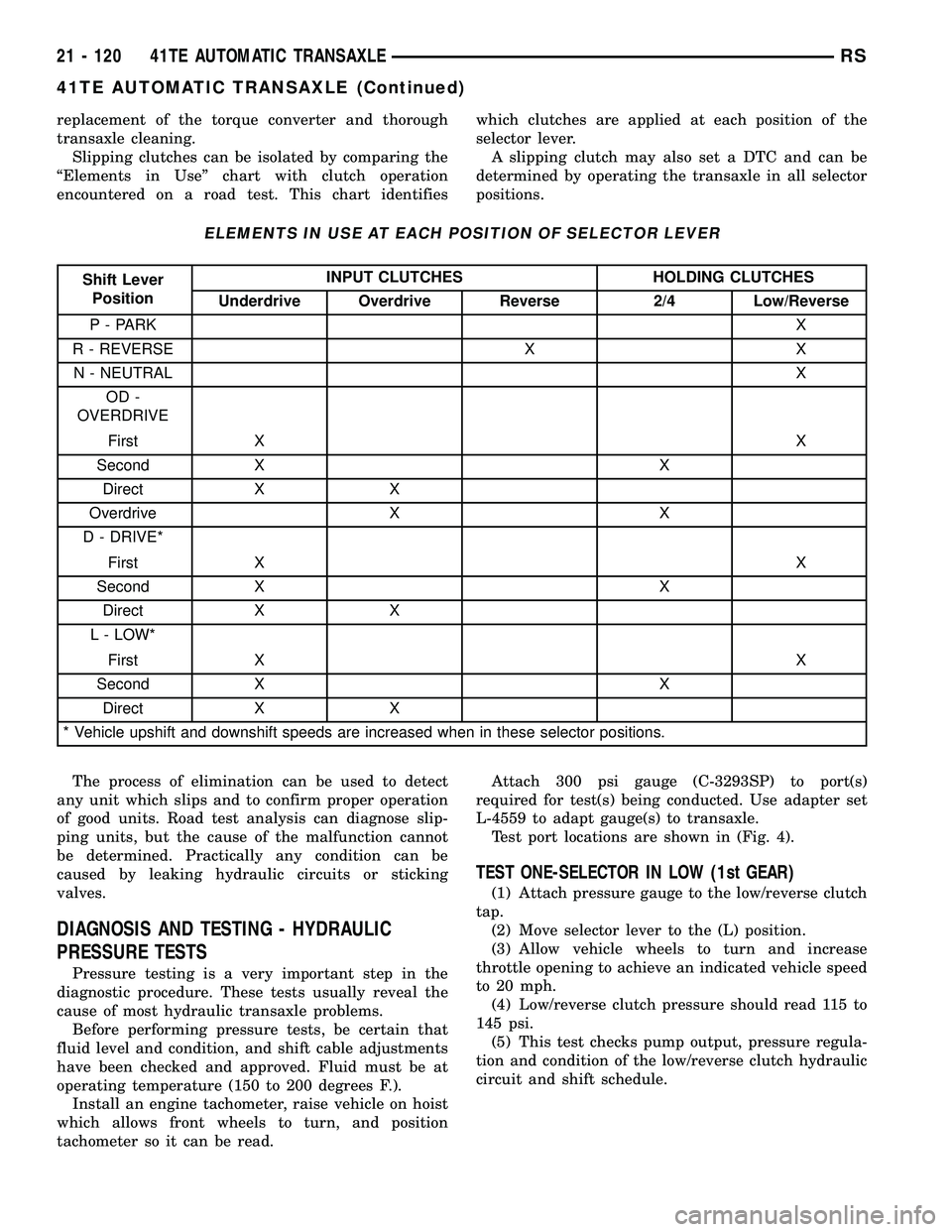
(3) Install selector cable to mount bracket and
secure with retainer clip (Fig. 172).
(4) Install cable to transaxle selector lever (Fig.
172).
(5)2.4L Gas models goto Step 10. 2.5L TD
models:Install coolant recovery bottle bracket (Fig.
173).(6) Install coolant recovery bottle to bracket.
(7) Connect battery temperature sensor to battery
tray. Install battery tray into position (Fig. 174).
Fig. 172 Gearshift Cables at Transaxle
1 - SELECTOR CABLE
2 - CABLE RETAINER
3 - CABLE RETAINER
4 - CROSSOVER CABLE
5 - MOUNT BRACKET
Fig. 173 Coolant Recovery Bottle Bracket
1 - COOLANT RECOVERY BOTTLE BRACKET
2 - NUT
3 - MOUNT BRACKET
Fig. 174 Battery Tray
1 - BATTERY TRAY
21 - 84 T850 MANUAL TRANSAXLERS
GEARSHIFT CABLE - SELECTOR (Continued)
Page 1717 of 2585

replacement of the torque converter and thorough
transaxle cleaning.
Slipping clutches can be isolated by comparing the
ªElements in Useº chart with clutch operation
encountered on a road test. This chart identifieswhich clutches are applied at each position of the
selector lever.
A slipping clutch may also set a DTC and can be
determined by operating the transaxle in all selector
positions.
ELEMENTS IN USE AT EACH POSITION OF SELECTOR LEVER
Shift Lever
PositionINPUT CLUTCHES HOLDING CLUTCHES
Underdrive Overdrive Reverse 2/4 Low/Reverse
P - PARKX
R - REVERSE X X
N - NEUTRALX
OD -
OVERDRIVE
First XX
Second X X
Direct X X
Overdrive X X
D - DRIVE*
First XX
Second X X
Direct X X
L - LOW*
First XX
Second X X
Direct X X
* Vehicle upshift and downshift speeds are increased when in these selector positions.
The process of elimination can be used to detect
any unit which slips and to confirm proper operation
of good units. Road test analysis can diagnose slip-
ping units, but the cause of the malfunction cannot
be determined. Practically any condition can be
caused by leaking hydraulic circuits or sticking
valves.
DIAGNOSIS AND TESTING - HYDRAULIC
PRESSURE TESTS
Pressure testing is a very important step in the
diagnostic procedure. These tests usually reveal the
cause of most hydraulic transaxle problems.
Before performing pressure tests, be certain that
fluid level and condition, and shift cable adjustments
have been checked and approved. Fluid must be at
operating temperature (150 to 200 degrees F.).
Install an engine tachometer, raise vehicle on hoist
which allows front wheels to turn, and position
tachometer so it can be read.Attach 300 psi gauge (C-3293SP) to port(s)
required for test(s) being conducted. Use adapter set
L-4559 to adapt gauge(s) to transaxle.
Test port locations are shown in (Fig. 4).
TEST ONE-SELECTOR IN LOW (1st GEAR)
(1) Attach pressure gauge to the low/reverse clutch
tap.
(2) Move selector lever to the (L) position.
(3) Allow vehicle wheels to turn and increase
throttle opening to achieve an indicated vehicle speed
to 20 mph.
(4) Low/reverse clutch pressure should read 115 to
145 psi.
(5) This test checks pump output, pressure regula-
tion and condition of the low/reverse clutch hydraulic
circuit and shift schedule.
21 - 120 41TE AUTOMATIC TRANSAXLERS
41TE AUTOMATIC TRANSAXLE (Continued)