2004 CHRYSLER VOYAGER Temperature
[x] Cancel search: TemperaturePage 1536 of 2585
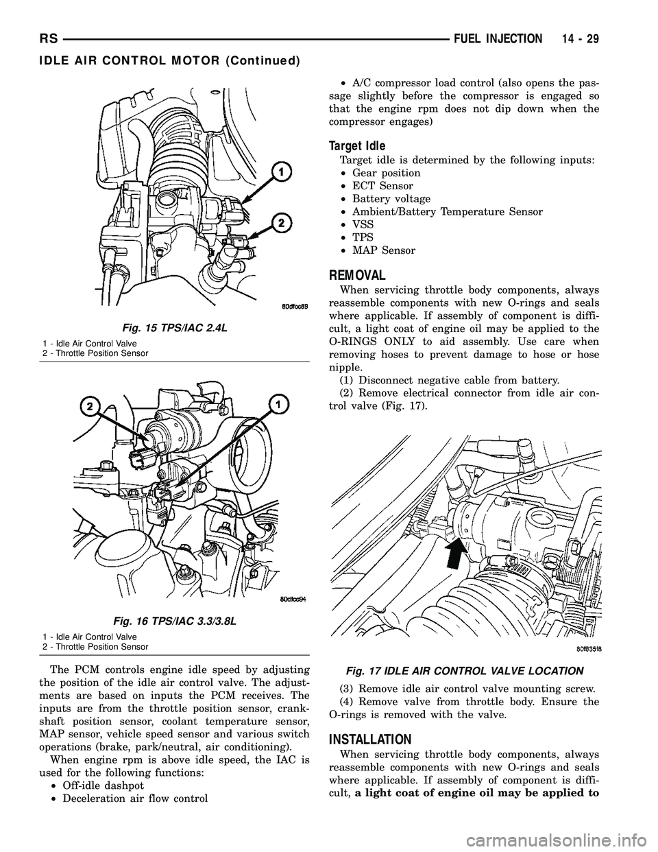
The PCM controls engine idle speed by adjusting
the position of the idle air control valve. The adjust-
ments are based on inputs the PCM receives. The
inputs are from the throttle position sensor, crank-
shaft position sensor, coolant temperature sensor,
MAP sensor, vehicle speed sensor and various switch
operations (brake, park/neutral, air conditioning).
When engine rpm is above idle speed, the IAC is
used for the following functions:
²Off-idle dashpot
²Deceleration air flow control²A/C compressor load control (also opens the pas-
sage slightly before the compressor is engaged so
that the engine rpm does not dip down when the
compressor engages)
Target Idle
Target idle is determined by the following inputs:
²Gear position
²ECT Sensor
²Battery voltage
²Ambient/Battery Temperature Sensor
²VSS
²TPS
²MAP Sensor
REMOVAL
When servicing throttle body components, always
reassemble components with new O-rings and seals
where applicable. If assembly of component is diffi-
cult, a light coat of engine oil may be applied to the
O-RINGS ONLY to aid assembly. Use care when
removing hoses to prevent damage to hose or hose
nipple.
(1) Disconnect negative cable from battery.
(2) Remove electrical connector from idle air con-
trol valve (Fig. 17).
(3) Remove idle air control valve mounting screw.
(4) Remove valve from throttle body. Ensure the
O-rings is removed with the valve.
INSTALLATION
When servicing throttle body components, always
reassemble components with new O-rings and seals
where applicable. If assembly of component is diffi-
cult,a light coat of engine oil may be applied to
Fig. 15 TPS/IAC 2.4L
1 - Idle Air Control Valve
2 - Throttle Position Sensor
Fig. 16 TPS/IAC 3.3/3.8L
1 - Idle Air Control Valve
2 - Throttle Position Sensor
Fig. 17 IDLE AIR CONTROL VALVE LOCATION
RSFUEL INJECTION14-29
IDLE AIR CONTROL MOTOR (Continued)
Page 1537 of 2585
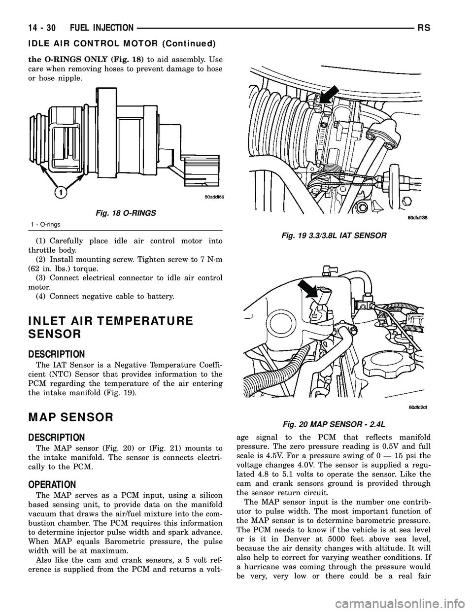
the O-RINGS ONLY (Fig. 18)to aid assembly. Use
care when removing hoses to prevent damage to hose
or hose nipple.
(1) Carefully place idle air control motor into
throttle body.
(2) Install mounting screw. Tighten screw to 7 N´m
(62 in. lbs.) torque.
(3) Connect electrical connector to idle air control
motor.
(4) Connect negative cable to battery.
INLET AIR TEMPERATURE
SENSOR
DESCRIPTION
The IAT Sensor is a Negative Temperature Coeffi-
cient (NTC) Sensor that provides information to the
PCM regarding the temperature of the air entering
the intake manifold (Fig. 19).
MAP SENSOR
DESCRIPTION
The MAP sensor (Fig. 20) or (Fig. 21) mounts to
the intake manifold. The sensor is connects electri-
cally to the PCM.
OPERATION
The MAP serves as a PCM input, using a silicon
based sensing unit, to provide data on the manifold
vacuum that draws the air/fuel mixture into the com-
bustion chamber. The PCM requires this information
to determine injector pulse width and spark advance.
When MAP equals Barometric pressure, the pulse
width will be at maximum.
Also like the cam and crank sensors, a 5 volt ref-
erence is supplied from the PCM and returns a volt-age signal to the PCM that reflects manifold
pressure. The zero pressure reading is 0.5V and full
scale is 4.5V. For a pressure swing of0Ð15psithe
voltage changes 4.0V. The sensor is supplied a regu-
lated 4.8 to 5.1 volts to operate the sensor. Like the
cam and crank sensors ground is provided through
the sensor return circuit.
The MAP sensor input is the number one contrib-
utor to pulse width. The most important function of
the MAP sensor is to determine barometric pressure.
The PCM needs to know if the vehicle is at sea level
or is it in Denver at 5000 feet above sea level,
because the air density changes with altitude. It will
also help to correct for varying weather conditions. If
a hurricane was coming through the pressure would
be very, very low or there could be a real fair
Fig. 18 O-RINGS
1 - O-rings
Fig. 19 3.3/3.8L IAT SENSOR
Fig. 20 MAP SENSOR - 2.4L
14 - 30 FUEL INJECTIONRS
IDLE AIR CONTROL MOTOR (Continued)
Page 1539 of 2585
O2 SENSOR
DESCRIPTION
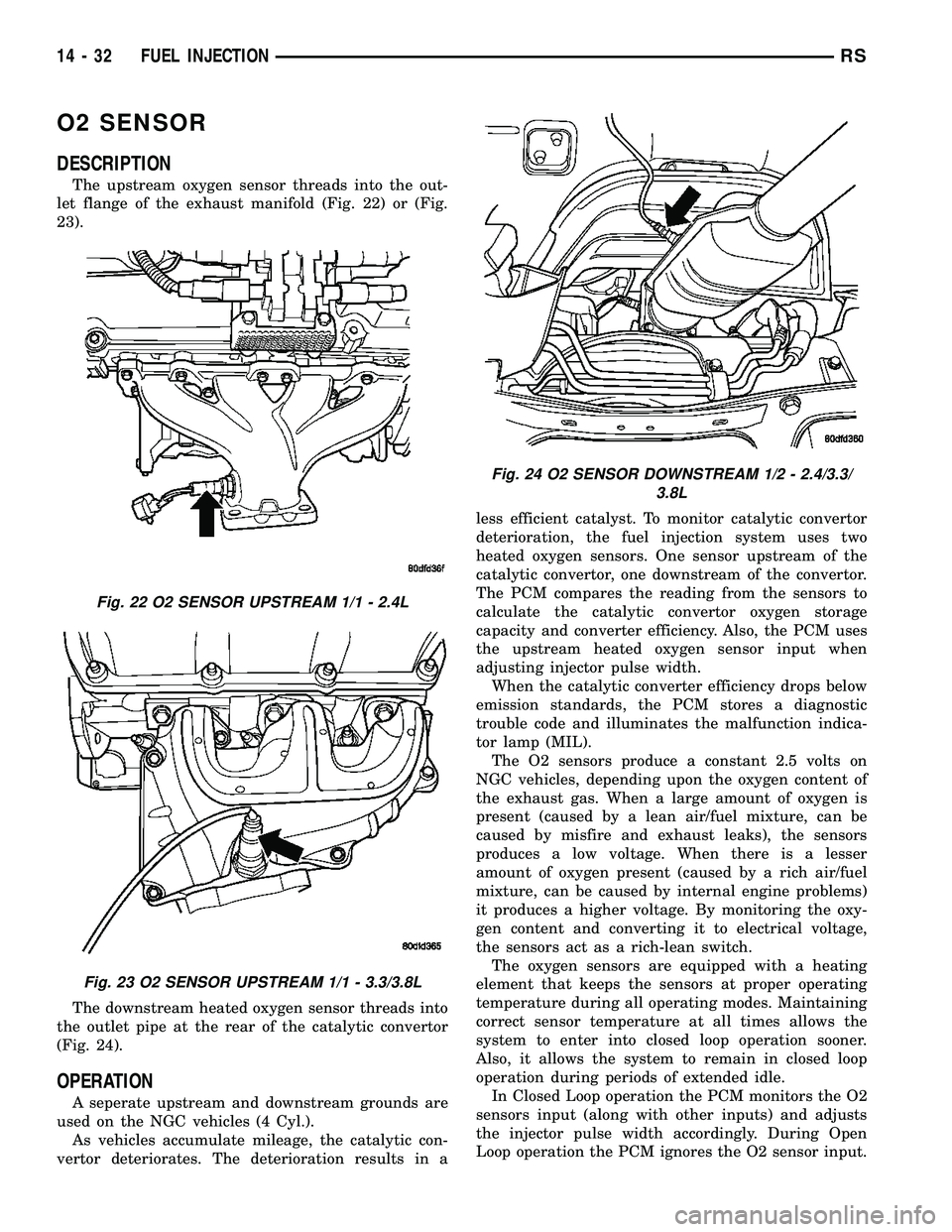
The upstream oxygen sensor threads into the out-
let flange of the exhaust manifold (Fig. 22) or (Fig.
23).
The downstream heated oxygen sensor threads into
the outlet pipe at the rear of the catalytic convertor
(Fig. 24).
OPERATION
A seperate upstream and downstream grounds are
used on the NGC vehicles (4 Cyl.).
As vehicles accumulate mileage, the catalytic con-
vertor deteriorates. The deterioration results in aless efficient catalyst. To monitor catalytic convertor
deterioration, the fuel injection system uses two
heated oxygen sensors. One sensor upstream of the
catalytic convertor, one downstream of the convertor.
The PCM compares the reading from the sensors to
calculate the catalytic convertor oxygen storage
capacity and converter efficiency. Also, the PCM uses
the upstream heated oxygen sensor input when
adjusting injector pulse width.
When the catalytic converter efficiency drops below
emission standards, the PCM stores a diagnostic
trouble code and illuminates the malfunction indica-
tor lamp (MIL).
The O2 sensors produce a constant 2.5 volts on
NGC vehicles, depending upon the oxygen content of
the exhaust gas. When a large amount of oxygen is
present (caused by a lean air/fuel mixture, can be
caused by misfire and exhaust leaks), the sensors
produces a low voltage. When there is a lesser
amount of oxygen present (caused by a rich air/fuel
mixture, can be caused by internal engine problems)
it produces a higher voltage. By monitoring the oxy-
gen content and converting it to electrical voltage,
the sensors act as a rich-lean switch.
The oxygen sensors are equipped with a heating
element that keeps the sensors at proper operating
temperature during all operating modes. Maintaining
correct sensor temperature at all times allows the
system to enter into closed loop operation sooner.
Also, it allows the system to remain in closed loop
operation during periods of extended idle.
In Closed Loop operation the PCM monitors the O2
sensors input (along with other inputs) and adjusts
the injector pulse width accordingly. During Open
Loop operation the PCM ignores the O2 sensor input.
Fig. 22 O2 SENSOR UPSTREAM 1/1 - 2.4L
Fig. 23 O2 SENSOR UPSTREAM 1/1 - 3.3/3.8L
Fig. 24 O2 SENSOR DOWNSTREAM 1/2 - 2.4/3.3/
3.8L
14 - 32 FUEL INJECTIONRS
Page 1543 of 2585
neously then gently pull the throttle cable from
throttle bracket or if it is the slide snap design you
have to slide the locking tab out of the hole and then
slide the cable assembly out of the bracket.
INSTALLATION
(1) From the engine compartment, push the hous-
ing end fitting and grommet into the dash panel.In-
stall gromment into the dash panel.
(2) Install the cable housing (throttle body end)
into the cable mounting bracket on the engine.
(3) From inside the vehicle, hold up the pedal and
install throttle cable and cable retainer in the upper
end of the pedal shaft.
(4) At the dash panel, install the cable retainer
clip between the end of the throttle cable fitting and
grommet
(5) From the engine compartment, rotate the
throttle lever wide open and install the throttle
cable.
THROTTLE POSITION SENSOR
DESCRIPTION
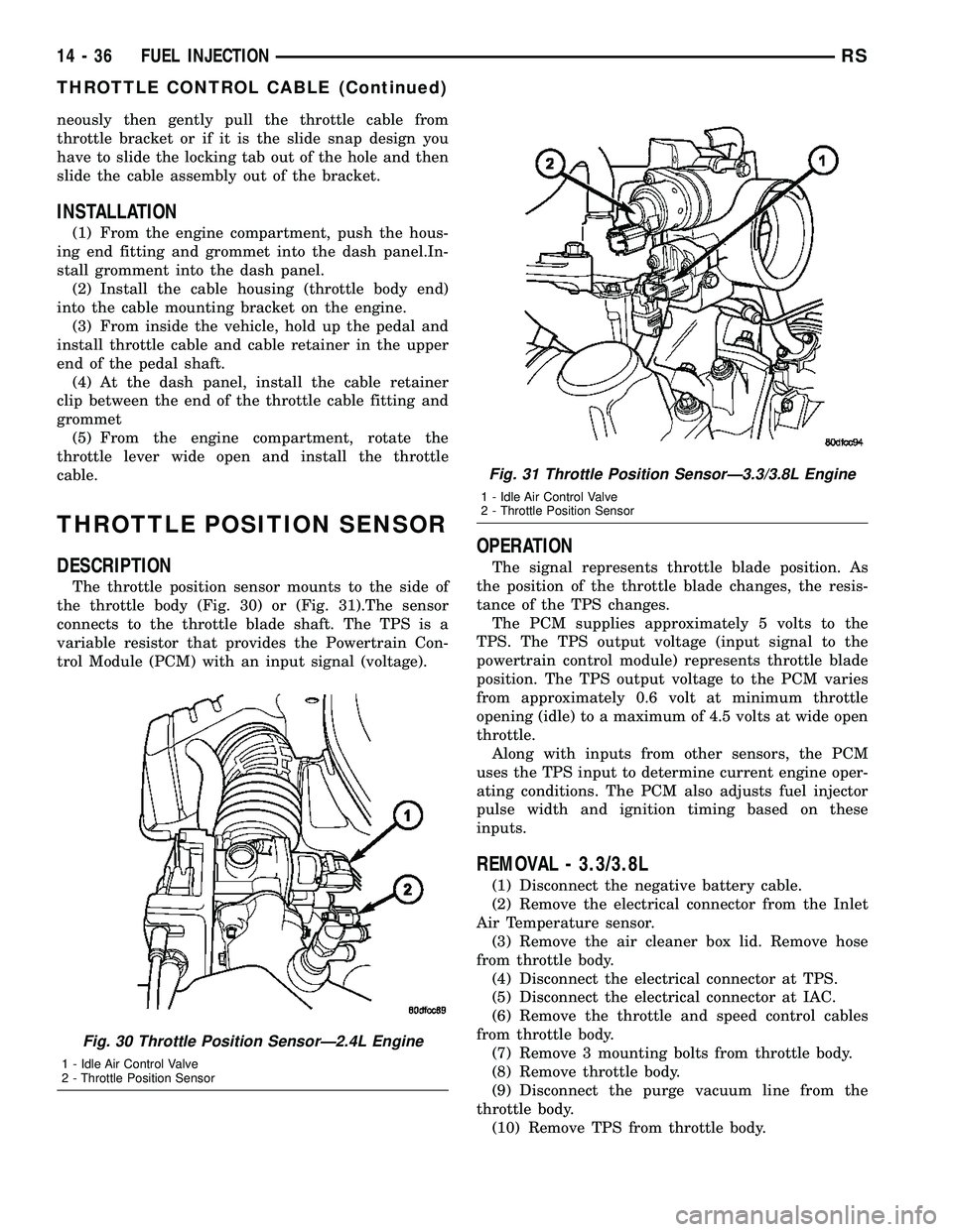
The throttle position sensor mounts to the side of
the throttle body (Fig. 30) or (Fig. 31).The sensor
connects to the throttle blade shaft. The TPS is a
variable resistor that provides the Powertrain Con-
trol Module (PCM) with an input signal (voltage).
OPERATION
The signal represents throttle blade position. As
the position of the throttle blade changes, the resis-
tance of the TPS changes.
The PCM supplies approximately 5 volts to the
TPS. The TPS output voltage (input signal to the
powertrain control module) represents throttle blade
position. The TPS output voltage to the PCM varies
from approximately 0.6 volt at minimum throttle
opening (idle) to a maximum of 4.5 volts at wide open
throttle.
Along with inputs from other sensors, the PCM
uses the TPS input to determine current engine oper-
ating conditions. The PCM also adjusts fuel injector
pulse width and ignition timing based on these
inputs.
REMOVAL - 3.3/3.8L
(1) Disconnect the negative battery cable.
(2) Remove the electrical connector from the Inlet
Air Temperature sensor.
(3) Remove the air cleaner box lid. Remove hose
from throttle body.
(4) Disconnect the electrical connector at TPS.
(5) Disconnect the electrical connector at IAC.
(6) Remove the throttle and speed control cables
from throttle body.
(7) Remove 3 mounting bolts from throttle body.
(8) Remove throttle body.
(9) Disconnect the purge vacuum line from the
throttle body.
(10) Remove TPS from throttle body.
Fig. 30 Throttle Position SensorÐ2.4L Engine
1 - Idle Air Control Valve
2 - Throttle Position Sensor
Fig. 31 Throttle Position SensorÐ3.3/3.8L Engine
1 - Idle Air Control Valve
2 - Throttle Position Sensor
14 - 36 FUEL INJECTIONRS
THROTTLE CONTROL CABLE (Continued)
Page 1544 of 2585
INSTALLATION - 3.3/3.8L
(1) Install TPS to throttle body.
(2) Disconnect the purge vacuum line from the
throttle body.
(3) Install throttle body.
(4) Install 3 mounting bolts from throttle body.
Tighten bolts.
(5) Install the throttle and speed control cables to
throttle body.(6) Connect the electrical connector at TPS.
(7) Connect the electrical connector at IAC.
(8) Install the air cleaner box lid. Install hose to
throttle body.
(9) Install the electrical connector to the Inlet Air
Temperature sensor.
(10) Connect the negative battery cable.
RSFUEL INJECTION14-37
THROTTLE POSITION SENSOR (Continued)
Page 1548 of 2585
(6) Start engine and let idle just long enough to
circulate power steering fluid through the analyzer
and hoses. Shut off engine.
(7) Check power steering fluid level and add fluid
as necessary. Start engine again and let idle until the
air is out of the fluid.
(8) Gauge should read below 300 psi (2068 kPa). If
above, inspect the hoses for restrictions and repair as
necessary. The initial pressure should be in the range
of 100-275 psi (689-1896 kPa) depending on fluid
temperature. The flow meter should read above 1.5
GPM.
CAUTION: The following test procedure involves
testing maximum pump pressure output and flow
control valve operation. Do not leave valve closed
for more than four seconds as the pump could be
damaged.
NOTE:
Power steering pump maximum pressure for
2.4L engines is 1,200 ± 1,350 psi (8,274 ± 9,308 kPa).
Power steering pump maximum pressure for all other
engines is 1,400 ± 1,500 psi (9,653 ± 10,342 kPa).
(9) Close analyzer valve fully three times and
record highest pressure indicated each time. All three
readings must be within specifications. If any of the
three power steering pump pressures are above orbelow specifications, replace pump. (Refer to 19 -
STEERING/PUMP - REMOVAL)
CAUTION: Do not force the steering to operate
against the stops for more than 4 seconds at a time
because pump damage can result.
(10) Once the pump has been verified as working
correctly, completely open the valve on the Power
Steering Analyzer. Turn the steering wheel to the
extreme left until the stop in the steering gear is
met. Hold it there for 2±4 seconds, then release it.
Now turn the steering wheel to the right until the
right stop is met. Hold it there for 2±4 seconds, then
release it. Record the stabilized pressure at each
position. Compare the recorded readings to the spec-
ifications. If the output pressures are not within 100
psi (689 kPa) of one another against either stop or
are below specifications, the steering gear is leaking
internally and must be replaced. (Refer to 19 -
STEERING/GEAR - REMOVAL)
DIAGNOSIS AND TESTING - STEERING
SYSTEM DIAGNOSIS CHARTS
NOTE: There are three diagnosis charts following
that cover POWER STEERING NOISE, STEERING
WHEEL FEEL, and POWER STEERING FLUID.
POWER STEERING NOISE
CONDITION POSSIBLE CAUSES CORRECTION
OBJECTIONABLE HISS
OR WHISTLE*1. Damaged or mispositioned
steering column shaft/coupling dash
panel seal.1. Reposition or replace steering column
shaft/coupling dash panel seal.
2. Noisy valve in power steering
gear.2. Replace power steering gear.
3. Mis-routed power steering hose. 3. Check routing of power steering
hoses. Ensure hoses do not come in
unwanted contact with other components
and objects.
RATTLE OR EXCESSIVE
CLUNK**1. Power steering gear loose on front
suspension crossmember.1. Inspect power steering gear mounting
bolts. Replace as necessary. Tighten to
the specified torque.
2. Front suspension crossmember
mounting fasteners loose at frame.2. Tighten the front suspension
crossmember mounting fasteners to the
specified torque.
3. Loose tie rod (outer or inner). 3. Check tie rod pivot points for wear.
Replace worn/loose parts as required.
4. Loose lower control arm mounting
bolts at front suspension
crossmember.4. Tighten control arm mounting bolts to
the specified torques.
RSSTEERING19-3
STEERING (Continued)
Page 1549 of 2585
CONDITION POSSIBLE CAUSES CORRECTION
5. Lower control arm pivot bushing
worn.5. Replace lower control arm pivot
bushing.
6. Loose strut assembly mounting
fasteners at tower or knuckle.6. Tighten strut assembly fasteners to the
specified torque.
7. Power steering fluid hose touching
the body of the vehicle.7. Adjust hose to proper position by
loosening, repositioning, and tightening
attachments to specified torque. Do not
bend tubing.
8. Internal power steering gear
noise.8. Replace power steering gear.
9. Damaged front suspension
crossmember.9. Replace front suspension
crossmember.
10. Stabilizer bar link ball joints
worn.10. Replace stabilizer bar link.
11. Lug nuts loose. 11. Tighten lug nuts to specifications.
12. Excessive Wheel bearing
free-play.12. Verify correct driveshaft hub nut
torque. Replace bearing if torque is okay.
POPPING NOISE 1. Worn outer tie rod. 1. Check ball joint for free-play; Replace
outer tie rod.
2. Loose inner tie rod. 2. Replace power steering gear.
CHIRP OR SQUEAL
(POWER STEERING
PUMP)1. Loose power steering pump drive
belt.1. Check and adjust power steering
pump drive belt to specifications or
replace automatic tensioner where
applicable. Replace belt if worn or
glazed.
2. Malfuctioning belt auto-tensioner 2. Replace belt auto-tensioner.
WHINE, GROWL, MOAN
OR GROAN (POWER
STEERING PUMP)***1. Low fluid level. 1. Fill power steering fluid reservoir to
proper level and check for leaks (make
sure all air is bled from the system fluid).
2. Power steering hose touching
vehicle body or frame.2. Adjust hose to proper position by
loosening, repositioning, and tightening
fitting to specified torque. Do not bend
tubing. Replace hose if damaged.
3. Extreme wear of power steering
pump internal components.3. Replace power steering pump and
flush system as necessary.
4. Extremely low ambient
temperature.4. Some noise can be expected, but will
go away as vehicle warms. Replace
pump if noise is excessive.
SUCKING AIR SOUND 1. Loose clamp on power steering
fluid return hose.1. Tighten or replace hose clamp.
2. Missing O-Ring on power steering
hose connection.2. Inspect connection and replace O-Ring
as required.
3. Low power steering fluid level. 3. Fill power steering fluid reservoir to
proper level and check for leaks.
4. Loose clamp on fluid supply hose. 4. Tighten or replace hose clamp.
19 - 4 STEERINGRS
STEERING (Continued)
Page 1553 of 2585
NOTE: * Steering shudder can be expected in new
vehicles and vehicles with recent steering system
repairs. Shudder should dissipate after the vehicle
has been driven several weeks.
NOTE: ** To evaluate this condition, it may be nec-
essary to disconnect the coupling at the base of the
steering column. Turn the steering wheel and feel or
listen for internal rubbing in steering column. To
avoid damaging the column clockspring, note the
following. Before disconnecting coupling, place
tires in the straight-ahead position and center steer-
ing wheel. Once disconnected, DO NOT rotate
steering wheel more than one revolution in eitherdirection and place steering wheel in original loca-
tion before reconnecting coupling. If this position is
lost, the steering column clockspring must be
recentered following the procedure found within the
procedure for steering column installation in the
steering column section.
NOTE: *** Increased low speed or stationary steer-
ing effort can be expected if the steering fluid is at
a high temperature. High fluid temperature usually
results from high engine rpm due to trailer towing,
ascending grades, or racing the engine for pro-
longed periods of time.
POWER STEERING FLUID
CONDITION POSSIBLE CAUSES CORRECTION
LOW FLUID LEVEL WITH
VISIBLE LEAK.1. Loose power steering hose
fittings.1. Tighten the fitting to its specified torque.
2. Damaged or missing fitting seal,
gasket, or O-ring.2. Replace as necessary.
3. Power steering component
leaking.3. Repair or replace the leaking component
as required.
AERATED FLUID.* 1. Low fluid level. 1. Fill power steering fluid reservoir to
proper level.
2. Air leak at supply hose, power
steering fluid reservoir or pump.2. Inspect for proper sealing. Repair as
necessary.
3. Cracked power steering pump
housing.3. Replace the power steering pump.
RESERVOIR FLUID
OVERFLOW AND FLUID
THAT IS MILKY IN COLOR1. Water contamination of power
steering fluid.1. Drain the power steering fluid from the
system. Flush the system with fresh clean
power steering fluid, drain, then refill to the
proper level.
NOTE: * Extremely cold temperatures may cause
power steering fluid aeration. Aeration should sub-
side as fluid warms.
19 - 8 STEERINGRS
STEERING (Continued)