Page 57 of 102

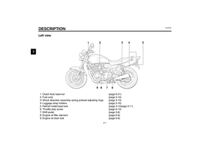
PERIODIC MAINTENANCE AND MINOR REPAIR
6-12
6
EC000082*
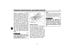
CAUTION:_ �
Make sure that the air filter ele-
ment is properly seated in the
air filter case.
�
The engine should never be op-
erated without the air filter ele-
ment installed, otherwise the
pistons and/or cylinders may
become excessively worn.
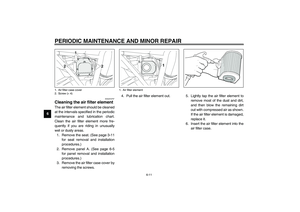
_7. Install the air filter case cover by
installing the screws.
8. Install the panel and the seat.
EAU00630
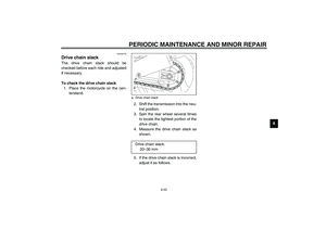
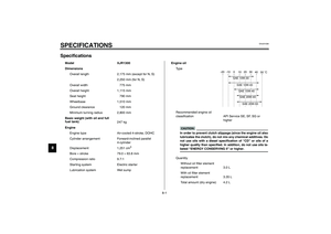
Adjusting the carburetors The carburetors are important parts of
the engine and require very sophisti-
cated adjustment. Therefore, most car-
buretor adjustments should be left to a
Yamaha dealer, who has the neces-
sary professional knowledge and expe-
rience. The adjustment described in
the following section, however, may be
serviced by the owner as part of routine
maintenance.
EC000095
CAUTION:_ The carburetors have been set and
extensively tested at the Yamaha
factory. Changing these settings
without sufficient technical knowl-
edge may result in poor perfor-
mance of or damage to the engine. _
U5WME0.book Page 12 Monday, July 29, 2002 10:25 AM
Page 58 of 102

PERIODIC MAINTENANCE AND MINOR REPAIR
6-13
6
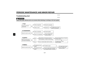
EAU04578
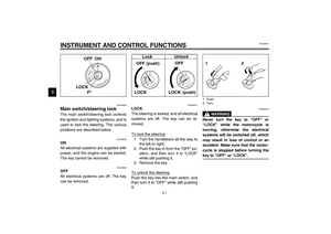
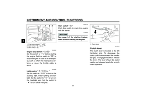
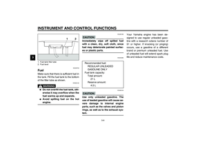
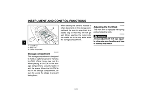
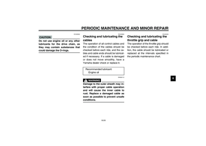
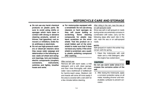
Adjusting the engine idling
speed The engine idling speed must be
checked and, if necessary, adjusted as
follows at the intervals specified in the
periodic maintenance and lubrication
chart.
The engine should be warm before
making this adjustment.NOTE:_ The engine is warm when it quickly re-
sponds to the throttle. _
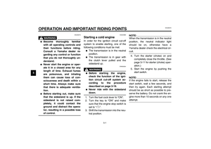
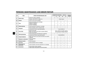
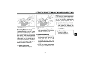
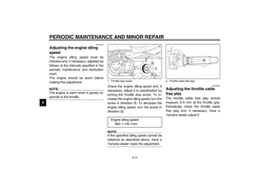
Check the engine idling speed and, if
necessary, adjust it to specification by
turning the throttle stop screw. To in-
crease the engine idling speed, turn the
screw in direction
a. To decrease the
engine idling speed, turn the screw in
direction
b.NOTE:_ If the specified idling speed cannot be
obtained as described above, have a
Yamaha dealer make the adjustment. _
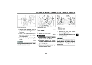
EAU00635
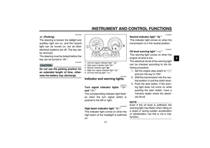
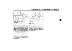
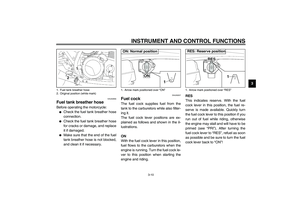
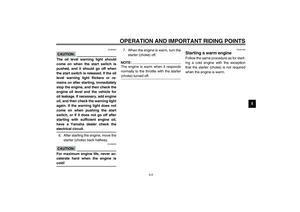
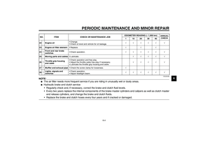
Adjusting the throttle cable
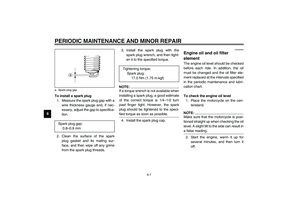
free play The throttle cable free play should
measure 3–5 mm at the throttle grip.
Periodically check the throttle cable
free play and, if necessary, have a
Yamaha dealer adjust it.
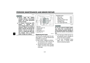
1. Throttle stop screw
Engine idling speed:
950–1,150 r/min
a. Throttle cable free play
U5WME0.book Page 13 Monday, July 29, 2002 10:25 AM
Page 59 of 102

PERIODIC MAINTENANCE AND MINOR REPAIR
6-14
6
EAU00637
Adjusting the valve clearance The valve clearance changes with use,
resulting in improper air-fuel mixture
and/or engine noise. To prevent this
from occurring, the valve clearance
must be adjusted by a Yamaha dealer
at the intervals specified in the periodic
maintenance and lubrication chart.
EAU00658
Tires To maximize the performance, durabil-
ity, and safe operation of your motor-
cycle, note the following points
regarding the specified tires.
Tire air pressure
The tire air pressure should be
checked and, if necessary, adjusted
before each ride.
EW000082
WARNING
_ �
The tire air pressure must be
checked and adjusted on cold
tires (i.e., when the temperature
of the tires equals the ambient
temperature).
�
The tire air pressure must be
adjusted in accordance with the
riding speed and with the total
weight of rider, passenger, car-
go, and accessories approved
for this model.
_
CE-01E
CE-07E
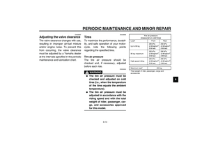
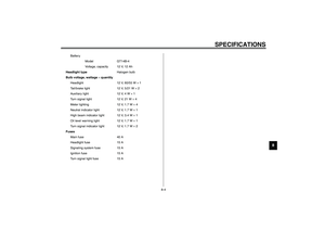
Tire air pressure
(measured on cold tires)
Load* Front Rear
Up to 90 kg250 kPa
(2.50 kgf/cm
2,
2.50 bar)250 kPa
(2.50 kgf/cm
2,
2.50 bar)
90 kg–maximum250 kPa
(2.50 kgf/cm
2,
2.50 bar)290 kPa
(2.90 kgf/cm
2,
2.90 bar)
High-speed riding250 kPa
(2.50 kgf/cm
2,
2.50 bar)290 kPa
(2.90 kgf/cm
2,
2.90 bar)
Maximum load* 203 kg
* Total weight of rider, passenger, cargo and
accessories
U5WME0.book Page 14 Monday, July 29, 2002 10:25 AM
Page 60 of 102

PERIODIC MAINTENANCE AND MINOR REPAIR
6-15
6
EWA00012
WARNING
_ Because loading has an enormous
impact on the handling, braking,
performance and safety characteris-
tics of your motorcycle, you should
keep the following precautions in
mind. �
NEVER OVERLOAD THE
MOTORCYCLE! Operation of an
overloaded motorcycle may re-
sult in tire damage, loss of con-
trol, or severe injury. Make sure
that the total weight of rider,
passenger, cargo, and accesso-
ries does not exceed the speci-
fied maximum load for the
vehicle.
�
Do not carry along loosely
packed items, which can shift
during a ride.
�
Securely pack the heaviest
items close to the center of the
motorcycle and distribute the
weight evenly on both sides.
�
Adjust the suspension and tire
air pressure with regard to the
load.
�
Check the tire condition and air
pressure before each ride.
_
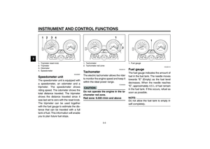
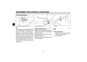
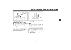
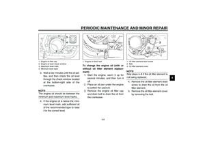
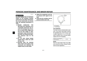
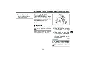
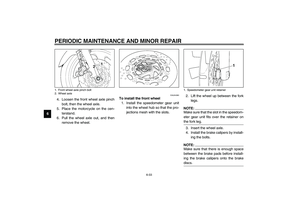
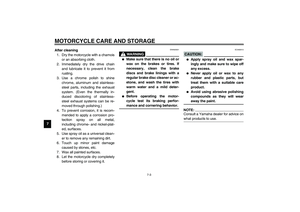
Tire inspection
The tires must be checked before each
ride. If the center tread depth reaches
the specified limit, if the tire has a nail
or glass fragments in it, or if the side-
wall is cracked, have a Yamaha dealer
replace the tire immediately.CE-08ENOTE:_ The tire tread depth limits may differ
from country to country. Always comply
with the local regulations. _1. Tire sidewall
a. Tire tread depthMinimum tire tread depth
(front and rear)1.6 mm
U5WME0.book Page 15 Monday, July 29, 2002 10:25 AM
Page 61 of 102

PERIODIC MAINTENANCE AND MINOR REPAIR
6-16
6
EW000079
WARNING
_ �
Have a Yamaha dealer replace
excessively worn tires. Besides
being illegal, operating the
motorcycle with excessively
worn tires decreases riding sta-
bility and can lead to loss of
control.
�
The replacement of all wheel-
and brake-related parts, includ-
ing the tires, should be left to a
Yamaha dealer, who has the
necessary professional knowl-
edge and experience.
_
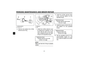
Tire information
This motorcycle is equipped with cast
wheels and tubeless tires with valves.
EW000080
WARNING
_ �
The front and rear tires should
be of the same make and de-
sign, otherwise the handling
characteristics of the motor-
cycle cannot be guaranteed.
�
After extensive tests, only the
tires listed below have been ap-
proved for this model by
Yamaha Motor Co., Ltd.
�
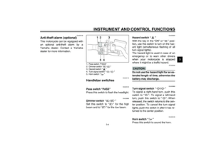
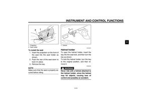
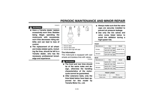
Always make sure that the valve
caps are securely installed to
prevent air pressure leakage.
�
Use only the tire valves and
valve cores listed below to
avoid tire deflation during a
high-speed ride.
_CE-10E
CE-14E
1. Tire air valve
2. Tire air valve core
3. Tire air valve cap with seal
FRONT
Manufacturer Size Model
Dunlop120/70 ZR17 (58W)
D220F ST M
120/70 ZR17 M/C (58W)
Michelin120/70 ZR17 (58W)
MACADAM90X E
120/70 ZR17 M/C (58W)
REAR
Manufacturer Size Model
Dunlop180/55 ZR17 (73W)
D220 ST M
180/55 ZR17 M/C (73W)
Michelin180/55 ZR17 (73W)
MACADAM90X E
180/55 ZR17 M/C (73W)FRONT & REAR
Tire air valve TR412
Valve core #9000A (original)
U5WME0.book Page 16 Monday, July 29, 2002 10:25 AM
Page 62 of 102

PERIODIC MAINTENANCE AND MINOR REPAIR
6-17
6
EAU00684
WARNING
_ This motorcycle is fitted with su-
per-high-speed tires. Note the fol-
lowing points in order to make the
most efficient use of these tires.�
Use only the specified replace-
ment tires. Other tires may run
the danger of bursting at super
high speeds.
�
Brand-new tires can have a rela-
tively poor grip on certain road
surfaces until they have been
“broken in”. Therefore, it is ad-
visable before doing any
high-speed riding to ride con-
servatively for approximately
100 km after installing a new
tire.
�
The tires must be warmed up
before a high-speed run.
�
Always adjust the tire air pres-
sure according to the operating
conditions.
_
EAU03773
Cast wheels To maximize the performance, durabil-
ity, and safe operation of your motor-
cycle, note the following points
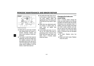
regarding the specified wheels.�
The wheel rims should be checked
for cracks, bends or warpage be-
fore each ride. If any damage is
found, have a Yamaha dealer re-
place the wheel. Do not attempt
even the smallest repair to the
wheel. A deformed or cracked
wheel must be replaced.
�
The wheel should be balanced
whenever either the tire or wheel
has been changed or replaced. An
unbalanced wheel can result in
poor performance, adverse han-
dling characteristics, and a short-
ened tire life.
�
Ride at moderate speeds after
changing a tire since the tire sur-
face must first be “broken in” for it
to develop its optimal characteris-
tics.
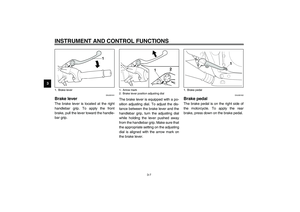
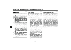
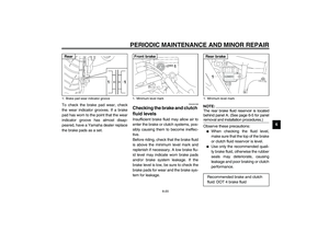
EAU00695
Clutch lever free play Since this model is equipped with a hy-
draulic clutch, adjusting the clutch lever
free play is not needed. However, it is
necessary to check the clutch fluid lev-
el and check the hydraulic system for
leakage before each ride. If the clutch
lever free play does become exces-
sive, and shifting becomes rough or
clutch slippage occurs, causing poor
acceleration, there may be air in the
clutch system. If there is air in the hy-
draulic system, have a Yamaha dealer
bleed the system before operating the
motorcycle.
U5WME0.book Page 17 Monday, July 29, 2002 10:25 AM
Page 63 of 102
PERIODIC MAINTENANCE AND MINOR REPAIR
6-18
6
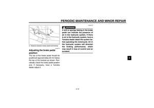
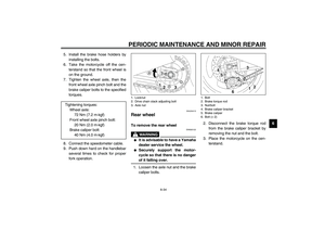
EAU00712
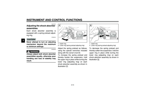
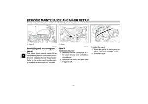
Adjusting the brake pedal
position The top of the brake pedal should be
positioned approximately 40 mm below
the top of the footrest as shown. Peri-
odically check the brake pedal position
and, if necessary, have a Yamaha
dealer adjust it.
EW000109
WARNING
_ A soft or spongy feeling in the brake
pedal can indicate the presence of
air in the hydraulic system. If there
is air in the hydraulic system, have a
Yamaha dealer bleed the system be-
fore operating the motorcycle. Air in
the hydraulic system will diminish
the braking performance, which
may result in loss of control and an
accident. _
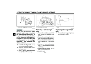
a. Distance between brake pedal and footrest
U5WME0.book Page 18 Monday, July 29, 2002 10:25 AM
Page 64 of 102

PERIODIC MAINTENANCE AND MINOR REPAIR
6-19
6
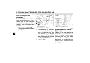
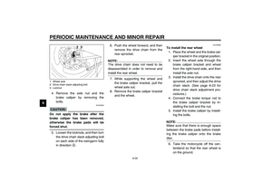
EAU01756
Rear brake light switch
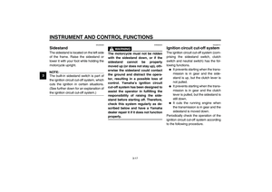
adjustment The rear brake light switch, which is ac-
tivated by the brake pedal, is properly
adjusted when the brake light comes
on just before braking takes effect. If
necessary, adjust the brake light switch
as follows.
1. Remove panel A. (See page 6-5
for panel removal and installation
procedures.)2. Turn the adjusting nut while hold-
ing the rear brake light switch in
place. To make the brake light
come on earlier, turn the adjusting
nut in direction
a. To make the
brake light come on later, turn the
adjusting nut in direction
b.
3. Install the panel.
EAU01314
Checking the front and rear
brake pads The front and rear brake pads must be
checked for wear at the intervals spec-
ified in the periodic maintenance and
lubrication chart. Each brake pad is
provided with a wear indicator groove,
which allows you to check the brake
pad wear without having to disassem-
ble the brake.
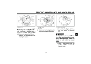
1. Rear brake light switch
2. Rear brake light switch adjusting nut
1. Brake pad wear indicator grooveFront
U5WME0.book Page 19 Monday, July 29, 2002 10:25 AM