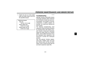
Page 25 of 102

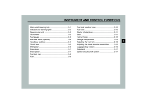
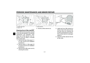
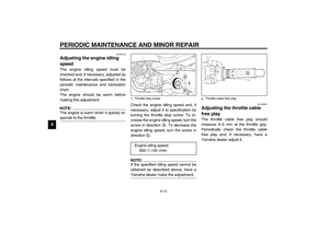
INSTRUMENT AND CONTROL FUNCTIONS
3-10
3
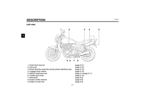
EAU02955
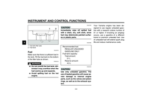
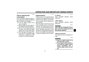
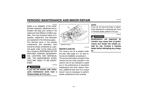
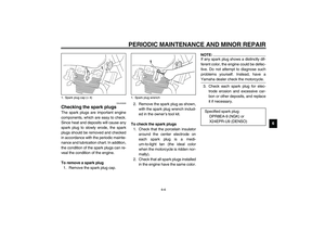
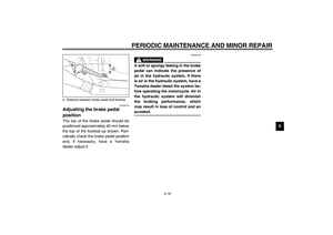
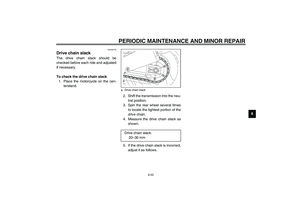
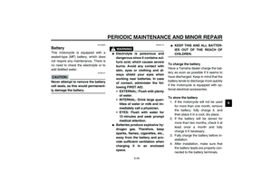
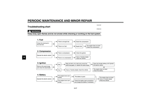
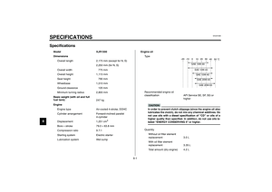
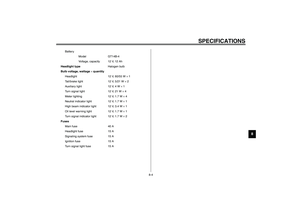
Fuel tank breather hose Before operating the motorcycle:�
Check the fuel tank breather hose
connection.
�
Check the fuel tank breather hose
for cracks or damage, and replace
it if damaged.
�
Make sure that the end of the fuel
tank breather hose is not blocked,
and clean it if necessary.
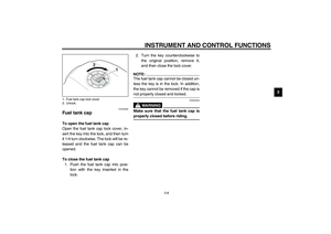
EAU00207
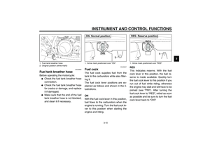
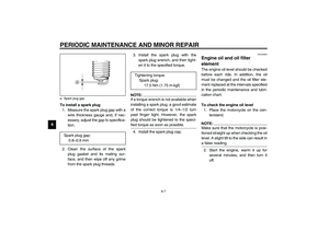
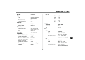
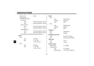
Fuel cock The fuel cock supplies fuel from the
tank to the carburetors while also filter-
ing it.
The fuel cock lever positions are ex-
plained as follows and shown in the il-
lustrations.
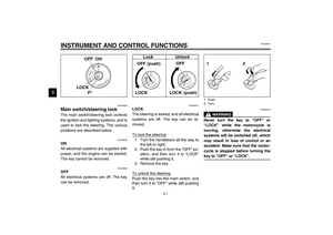
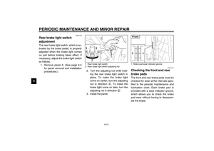
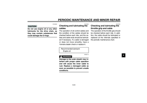
ON
With the fuel cock lever in this position,
fuel flows to the carburetors when the
engine is running. Turn the fuel cock le-
ver to this position when starting the
engine and riding.RES
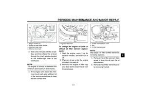
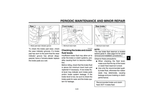
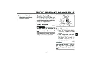
This indicates reserve. With the fuel
cock lever in this position, the fuel re-
serve is made available. Quickly turn
the fuel cock lever to this position if you
run out of fuel while riding, otherwise
the engine may stall and will have to be
primed (see “PRI”). After turning the
fuel cock lever to “RES”, refuel as soon
as possible and be sure to turn the fuel
cock lever back to “ON”!
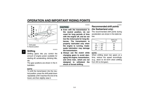
1. Fuel tank breather hose
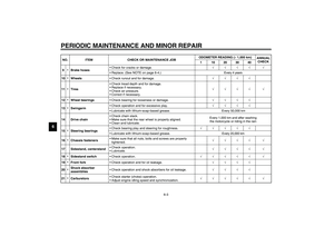
2. Original position (white mark)
1. Arrow mark positioned over “ON”ON: Normal position
1. Arrow mark positioned over “RES”RES: Reserve position
U5WME0.book Page 10 Monday, July 29, 2002 10:25 AM
Page 26 of 102
INSTRUMENT AND CONTROL FUNCTIONS
3-11
3
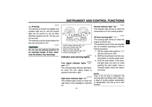
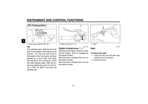
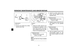
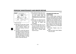
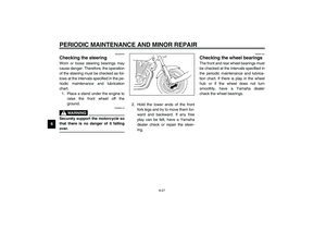
PRI
This indicates prime. With the fuel cock
lever in this position, the engine can be
“primed”. Turn the fuel cock lever to
this position when the engine has been
allowed to run out of fuel. This sends
fuel directly to the carburetors, which
will make starting easier. After the en-
gine has started, be sure to turn the le-
ver to “ON” (or “RES” if you have not
refueled yet).
EAU03839
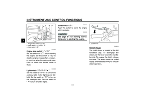
Starter (choke) lever “” Starting a cold engine requires a richer
air-fuel mixture, which is supplied by
the starter (choke).
Move the lever in direction
a to turn on
the starter (choke).
Move the lever in direction
b to turn off
the starter (choke).
EAU04406
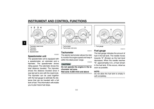
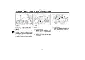
Seat To remove the seat
1. Insert the key into the seat lock,
and then turn it as shown.
2. Pull the seat off.
1. Arrow mark positioned over “PRI”PRI: Priming position
1. Starter (choke) lever “”
1. Unlock.
U5WME0.book Page 11 Monday, July 29, 2002 10:25 AM
Page 27 of 102
INSTRUMENT AND CONTROL FUNCTIONS
3-12
3
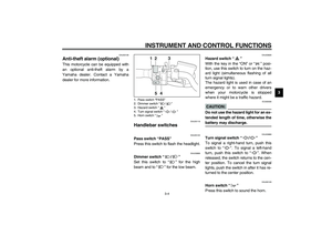
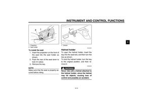
To install the seat
1. Insert the projection on the front of
the seat into the seat holder as
shown.
2. Push the rear of the seat down to
lock it in place.
3. Remove the key.
NOTE:_ Make sure that the seat is properly se-
cured before riding. _
EAU04291
Helmet holder To open the helmet holder, insert the
key into the seat lock, and then turn the
key as shown.
To lock the helmet holder, turn the key
to the original position, and then re-
move it.
EW000030
WARNING
_ Never ride with a helmet attached to
the helmet holder, since the helmet
may hit objects, causing loss of
control and possibly an accident. _
1. Projection
2. Seat holder
1. Unlock.
U5WME0.book Page 12 Monday, July 29, 2002 10:25 AM
Page 28 of 102
INSTRUMENT AND CONTROL FUNCTIONS
3-13
3
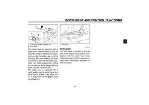
EAU04292
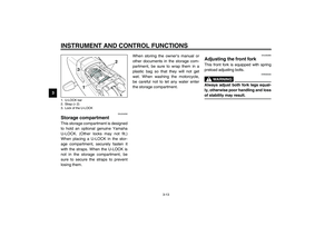
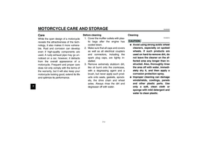
Storage compartment This storage compartment is designed
to hold an optional genuine Yamaha
U-LOCK. (Other locks may not fit.)
When placing a U-LOCK in the stor-
age compartment, securely fasten it
with the straps. When the U-LOCK is
not in the storage compartment, be
sure to secure the straps to prevent
losing them.When storing the owner’s manual or
other documents in the storage com-
partment, be sure to wrap them in a
plastic bag so that they will not get
wet. When washing the motorcycle,
be careful not to let any water enter
the storage compartment.
EAU00285
Adjusting the front fork This front fork is equipped with spring
preload adjusting bolts.
EW000035
WARNING
_ Always adjust both fork legs equal-
ly, otherwise poor handling and loss
of stability may result. _
1. U-LOCK bar
2. Strap (× 2)
3. Lock of the U-LOCKU5WME0.book Page 13 Monday, July 29, 2002 10:25 AM
Page 29 of 102
INSTRUMENT AND CONTROL FUNCTIONS
3-14
3
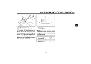
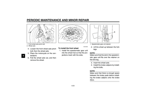
Adjust the spring preload as follows.
To increase the spring preload and
thereby harden the suspension, turn
the adjusting bolt on each fork leg in di-
rection
a. To decrease the spring pre-
load and thereby soften the
suspension, turn the adjusting bolt on
each fork leg in direction
b.
NOTE:_ Align the appropriate groove on the ad-
justing mechanism with the top of the
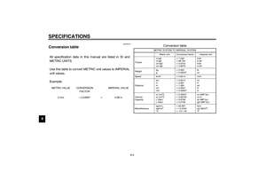
front fork cap bolt. _CI-10E
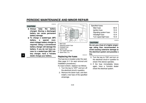
1. Spring preload adjusting bolt
1. Current setting
2. Front fork cap bolt
Setting
Minimum (soft) 7
Standard 5
Maximum (hard) 1
U5WME0.book Page 14 Monday, July 29, 2002 10:25 AM
Page 30 of 102

INSTRUMENT AND CONTROL FUNCTIONS
3-15
3
EAU04407
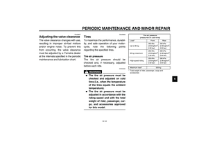
Adjusting the shock absorber
assemblies Each shock absorber assembly is
equipped with a spring preload adjust-
ing ring.
EC000015
CAUTION:_ Never attempt to turn an adjusting
mechanism beyond the maximum
or minimum settings. _
EW000040
WARNING
_ Always adjust both shock absorber
assemblies equally, otherwise poor
handling and loss of stability may
result. _
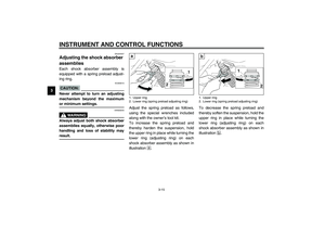
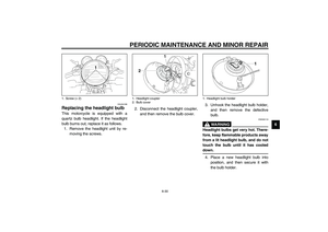
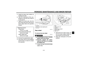
Adjust the spring preload as follows,
using the special wrenches included
along with the owner’s tool kit.
To increase the spring preload and
thereby harden the suspension, hold
the upper ring in place while turning the
lower ring (adjusting ring) on each
shock absorber assembly as shown in
illustration
+.To decrease the spring preload and
thereby soften the suspension, hold the
upper ring in place while turning the
lower ring (adjusting ring) on each
shock absorber assembly as shown in
illustration
,.1. Upper ring
2. Lower ring (spring preload adjusting ring)
1. Upper ring
2. Lower ring (spring preload adjusting ring)
U5WME0.book Page 15 Monday, July 29, 2002 10:25 AM
Page 31 of 102
INSTRUMENT AND CONTROL FUNCTIONS
3-16
3
EAU00316
WARNING
_ These shock absorbers contain
highly pressurized nitrogen gas. For
proper handling read and under-
stand the following information be-
fore handling the shock absorbers.
The manufacturer cannot be held re-
sponsible for property damage or
personal injury that may result from
improper handling.�
Do not tamper with or attempt to
open the gas cylinders.
�
Do not subject the shock ab-
sorbers to an open flame or oth-
er high heat sources, otherwise
they may explode due to exces-
sive gas pressure.
�
Do not deform or damage the
gas cylinders in any way, as this
will result in poor damping per-
formance.
�
Always have a Yamaha dealer
service the shock absorbers.
_
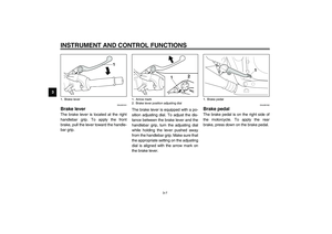
EAU04276
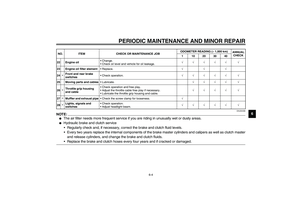
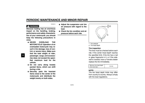
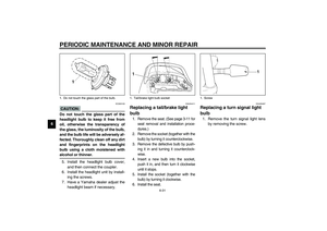
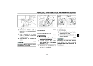
Luggage strap holders There are four luggage strap holders,
two of which can be turned out for eas-
ier access.1. Luggage strap holder (× 4)
U5WME0.book Page 16 Monday, July 29, 2002 10:25 AM
Page 32 of 102

INSTRUMENT AND CONTROL FUNCTIONS
3-17
3
EAU00330
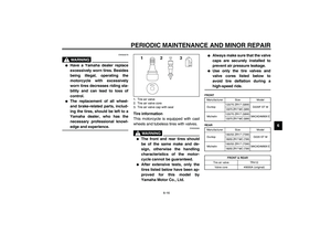
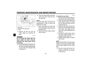
Sidestand The sidestand is located on the left side
of the frame. Raise the sidestand or
lower it with your foot while holding the
motorcycle upright.NOTE:_ The built-in sidestand switch is part of
the ignition circuit cut-off system, which
cuts the ignition in certain situations.
(See further down for an explanation of
the ignition circuit cut-off system.) _
EW000044
WARNING
_ The motorcycle must not be ridden
with the sidestand down, or if the
sidestand cannot be properly
moved up (or does not stay up), oth-
erwise the sidestand could contact
the ground and distract the opera-
tor, resulting in a possible loss of
control. Yamaha’s ignition circuit
cut-off system has been designed to
assist the operator in fulfilling the
responsibility of raising the side-
stand before starting off. Therefore,
check this system regularly as de-
scribed below and have a Yamaha
dealer repair it if it does not function
properly. _
EAU03741
Ignition circuit cut-off system The ignition circuit cut-off system (com-
prising the sidestand switch, clutch
switch and neutral switch) has the fol-
lowing functions.�
It prevents starting when the trans-
mission is in gear and the side-
stand is up, but the clutch lever is
not pulled.
�
It prevents starting when the trans-
mission is in gear and the clutch
lever is pulled, but the sidestand is
still down.
�
It cuts the running engine when
the transmission is in gear and the
sidestand is moved down.
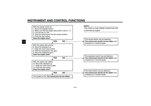
Periodically check the operation of the
ignition circuit cut-off system according
to the following procedure.
U5WME0.book Page 17 Monday, July 29, 2002 10:25 AM


When placing a U-LOCK in")

