Page 57 of 110
, do not
mix any chemical additives.
Do not use oils wi")
6-11
PERIODIC MAINTENANCE AND MINOR REPAIR
6
ECA00133
cC
8In order to prevent clutch slip-
page (since the engine oil also
lubricates the clutch), do not
mix any chemical additives.
Do not use oils with a diesel
specification of “CD” or oils of
a higher quality than specified.
In addition, do not use oils
labeled “ENERGY CONSERV-
ING II” or higher.
8Make sure that no foreign
material enters the crankcase.
9. Start the engine, and then let it
idle for several minutes while
checking it for oil leakage. If oil is
leaking, immediately turn the
engine off and check for the
cause.
10. Turn the engine off, and then
check the oil level and correct it if
necessary.2. Check the coolant level in the
coolant reservoir.
NOTE:
The coolant should be between the
minimum and maximum level marks.
1. Coolant reservoir
2. Maximum level mark
3. Minimum level mark
EAU04879
CoolantCoolantThe coolant level should be checked
before each ride. In addition, the
coolant must be changed at the inter-
vals specified in the periodic mainte-
nance and lubrication chart.
To check the coolant level
Checking1. Place the motorcycle on the cen-
terstand.
NOTE:
8The coolant level must be
checked on a cold engine since
the level varies with engine tem-
perature.
8Make sure that the motorcycle is
positioned straight up when
checking the coolant level. A
slight tilt to the side can result in
a false reading.
5PS-28199-E1 8/29/02 9:16 AM Page 56
Page 58 of 110
, remove the reservo")
6-12
PERIODIC MAINTENANCE AND MINOR REPAIR
6 3. If the coolant is at or below the
minimum level mark, remove
panel B (See page 6-6 for panel
removal and installation proce-
dures.), remove the reservoir
cap, add coolant to the maximum
level mark, and then install the
reservoir cap and the panel.
1. Coolant reservoir cap
EW000067
w
Never attempt to remove the radia-
tor cap when the engine is hot.
NOTE:
8The radiator fan is automatically
switched on or off according to
the coolant temperature in the
radiator.
8If the engine overheats, see
page 6-45 for further instructions.
EC000080
cC
8If coolant is not available, use
distilled water or soft tap water
instead. Do not use hard water
or salt water since it is harmful
to the engine.
8If water has been used instead
of coolant, replace it with
coolant as soon as possible,
otherwise the engine may not
be sufficiently cooled and the
cooling system will not be pro-
tected against frost and corro-
sion.
8If water has been added to the
coolant, have a Yamaha dealer
check the antifreeze content of
the coolant as soon as possi-
ble, otherwise the effective-
ness of the coolant will be
reduced.
Coolant reservoir capacity
(up to the maximum level mark):
0.25 L
5PS-28199-E1 8/29/02 9:16 AM Page 57
Page 59 of 110
6-13
PERIODIC MAINTENANCE AND MINOR REPAIR
6
EAU04461
To change the coolantChanging1. Place the motorcycle on a level
surface and let the engine cool if
necessary.
2. Remove the seat. (See page
3-13 for seat removal and instal-
lation procedures.)
3. Remove cowling B and panel B.
(See pages 6-5 and 6-6 for cowl-
ing and panel removal and instal-
lation procedures.)
4. Remove the fuel tank bolts, and
then lift the fuel tank to position it
away from the coolant reservoir.
(Do not disconnect the fuel
hoses!)
5. Place a container under the
engine to collect the used
coolant.7. Remove the coolant drain bolts
to drain the cooling system.
11
1. Coolant drain bolt (×2)
6. Remove the radiator cap retain-
ing bolt and the radiator cap.
EW000067
w
Never attempt to remove the radia-
tor cap when the engine is hot.
1. Radiator cap retaining bolt
2. Radiator cap
5PS-28199-E1 8/29/02 9:16 AM Page 58
Page 60 of 110

6-14
PERIODIC MAINTENANCE AND MINOR REPAIR
6 8. Remove the coolant reservoir
bolt.
9. Pull the coolant reservoir upward
and away from the motorcycle.
10. Drain the remaining coolant from
the coolant reservoir by opening
the cap, then turning the reser-
voir upside down.
11. Install the coolant reservoir by
placing it in the original position,
then installing the bolt.
12. After the coolant is completely
drained, thoroughly flush the
cooling system with clean tap
water.
1. Bolt
2. Coolant reservoir
13. Install the coolant drain bolts,
and then tighten them to the
specified torque.
NOTE:
Check the washers for damage and
replace them if necessary.
14. Pour the recommended coolant
into the radiator until it is full. Tightening torque:
Coolant drain bolt:
10 Nm (1.0 m·kgf)
Antifreeze/water mixture ratio:
1:1
Recommended antifreeze:
High-quality ethylene glycol
antifreeze containing corrosion
inhibitors for aluminum engines
Coolant quantity:
Total amount:
1.7 L
Coolant reservoir capacity:
0.25 L
5PS-28199-E1 8/29/02 9:16 AM Page 59
Page 61 of 110

6-15
PERIODIC MAINTENANCE AND MINOR REPAIR
6
EC000080
cC
8If coolant is not available, use
distilled water or soft tap water
instead. Do not use hard water
or salt water since it is harmful
to the engine.
8If water has been used instead
of coolant, replace it with
coolant as soon as possible,
otherwise the engine may not
be sufficiently cooled and the
cooling system will not be pro-
tected against frost and corro-
sion.
8If water has been added to the
coolant, have a Yamaha dealer
check the antifreeze content of
the coolant as soon as possi-
ble, otherwise the effective-
ness of the coolant will be
reduced.
EWA00052
w
8Before installing the fuel tank,
make sure that the fuel hoses
are not damaged. If any fuel
hose is damaged, do not start
the engine but have a Yamaha
dealer replace the hose, other-
wise fuel may leak.
8Make sure that the fuel hoses
are properly connected and
routed, and not pinched.
8Be sure to place the fuel tank
breather hose in the original
position.
19. Install the panel, the cowling,
and the seat.
20. Start the engine, and then check
the vehicle for coolant leakage. If
coolant is leaking, have a
Yamaha dealer check the cool-
ing system. 15. Install the radiator cap, start the
engine, let it idle for several min-
utes, and then turn it off.
16. Remove the radiator cap to
check the coolant level in the
radiator. If necessary, add suffi-
cient coolant until it reaches the
top of the radiator, and then
install the radiator cap and the
cap retaining bolt.
17. Check the coolant level in the
reservoir. If necessary, remove
the coolant reservoir cap, add
coolant to the maximum level
mark, and then install the cap.
18. Install the fuel tank.
5PS-28199-E1 8/29/02 9:16 AM Page 60
Page 62 of 110

6-16
PERIODIC MAINTENANCE AND MINOR REPAIR
6
EAU04973
Replacing the air filter
element
Air filter element, replacingThe air filter element should be
replaced at the intervals specified in
the periodic maintenance and lubrica-
tion chart. Replace the air filter ele-
ment more frequently if you are riding
in unusually wet or dusty areas.
1. Remove the seat. (See page
3-13 for seat removal and instal-
lation procedures.)
2. Remove cowlings A and B as
well as panels A and B. (See
pages 6-5 and 6-6 for cowling
and panel removal and installa-
tion procedures.)
1. Bolt (×2)
6. Insert a new air filter element into
the air filter case.
EC000082
cC
8Make sure that the air filter ele-
ment is properly seated in the
air filter case.
8The engine should never be
operated without the air filter
element installed, otherwise
the pistons and/or cylinders
may become excessively
worn.
1. Air filter element
3. Remove the fuel tank bolts, and
then lift the fuel tank away from
the air filter case.
4. Remove the air filter case cover
by removing the screws.
5. Pull the air filter element out.
1. Air filter case cover
2. Screw (×8)
5PS-28199-E1 8/29/02 9:16 AM Page 61
Page 63 of 110

6-17
PERIODIC MAINTENANCE AND MINOR REPAIR
67. Install the air filter case cover by
installing the screws.
8. Place the fuel tank in the original
position and install the bolts.
EWA00067
w
8Before installing the fuel tank,
make sure that the fuel hoses
are not damaged. If any fuel
hose is damaged, do not start
the engine but have a Yamaha
dealer replace the hose, other-
wise fuel may leak.
8Make sure that the fuel hoses
are properly connected and
routed, and not pinched.
8Be sure to place the fuel tank
breather hose and the fuel
tank overflow hose in the orig-
inal position.
9. Install the panels and cowlings.
10. Install the seat.Check the engine idling speed and, if
necessary, adjust it to specification
by turning the throttle stop screw. To
increase the engine idling speed, turn
the screw in direction a. To
decrease the engine idling speed,
turn the screw in direction b.
NOTE:
If the specified idling speed cannot
be obtained as described above,
have a Yamaha dealer make the
adjustment.
1. Throttle stop screw
EAU04578
Adjusting the engine idling
speed
Engine idling speedThe engine idling speed must be
checked and, if necessary, adjusted
as follows at the intervals specified in
the periodic maintenance and lubrica-
tion chart.
The engine should be warm before
making this adjustment.
NOTE:
The engine is warm when it quickly
responds to the throttle.
Engine idling speed:
1,100–1,200 r/min
5PS-28199-E1 8/29/02 9:16 AM Page 62
Page 64 of 110

6-18
PERIODIC MAINTENANCE AND MINOR REPAIR
6
EAU00635
Adjusting the throttle cable
free play
Throttle cable free play, adjustingThe throttle cable free play should
measure 3–5 mm at the throttle grip.
Periodically check the throttle cable
free play and, if necessary, have a
Yamaha dealer adjust it.
a
a. Throttle cable free play
EAU00658
TiresTiresTo maximize the performance, dura-
bility, and safe operation of your
motorcycle, note the following points
regarding the specified tires.
Tire air pressure
The tire air pressure should be
checked and, if necessary, adjusted
before each ride.
EW000082
w
8The tire air pressure must be
checked and adjusted on cold
tires (i.e., when the tempera-
ture of the tires equals the
ambient temperature).
8The tire air pressure must be
adjusted in accordance with
the riding speed and with the
total weight of rider, passen-
ger, cargo, and accessories
approved for this model.
EAU00637
Adjusting the valve
clearance
Valve clearance, adjustingThe valve clearance changes with
use, resulting in improper air-fuel mix-
ture and/or engine noise. To prevent
this from occurring, the valve clear-
ance must be adjusted by a Yamaha
dealer at the intervals specified in the
periodic maintenance and lubrication
chart.
5PS-28199-E1 8/29/02 9:16 AM Page 63
 1
1 2
2 3
3 4
4 5
5 6
6 7
7 8
8 9
9 10
10 11
11 12
12 13
13 14
14 15
15 16
16 17
17 18
18 19
19 20
20 21
21 22
22 23
23 24
24 25
25 26
26 27
27 28
28 29
29 30
30 31
31 32
32 33
33 34
34 35
35 36
36 37
37 38
38 39
39 40
40 41
41 42
42 43
43 44
44 45
45 46
46 47
47 48
48 49
49 50
50 51
51 52
52 53
53 54
54 55
55 56
56 57
57 58
58 59
59 60
60 61
61 62
62 63
63 64
64 65
65 66
66 67
67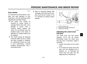 68
68 69
69 70
70 71
71 72
72 73
73 74
74 75
75 76
76 77
77 78
78 79
79 80
80 81
81 82
82 83
83 84
84 85
85 86
86 87
87 88
88 89
89 90
90 91
91 92
92 93
93 94
94 95
95 96
96 97
97 98
98 99
99 100
100 101
101 102
102 103
103 104
104 105
105 106
106 107
107 108
108 109
109