Page 17 of 110

3-3
INSTRUMENT AND CONTROL FUNCTIONS
3
EAU04877
Oil level warning light “7”Oil level warning lightThis warning light comes on when
the engine oil level is low.
The electrical circuit of the warning
light can be checked by turning the
key to “ON”.
If the warning light does not come on
for a few seconds, then go off, have a
Yamaha dealer check the electrical
circuit.
NOTE:
Even if the oil level is sufficient, the
warning light may flicker when riding
on a slope or during sudden acceler-
ation or deceleration, but this is not a
malfunction.
1. Fuel level warning symbol “ ”
2. Left turn signal indicator light “4”
3. High beam indicator light “&”
4. Neutral indicator light “N”
5. Engine trouble indicator light “ ”
6. Right turn signal indicator light “6”
7. Oil level warning light “
7”
EAU04121
Turn signal indicator lights “4”
and “6”
Turn signal indicator lightsThe corresponding indicator light
flashes when the turn signal switch is
pushed to the left or right.
EAU00063
High beam indicator light “&”High beam indicator lightThis indicator light comes on when
the high beam of the headlight is
switched on.
EAU00061
Neutral indicator light “N”Neutral indicator lightThis indicator light comes on when
the transmission is in the neutral
position.
EAU04585
Engine trouble warning light “”Engine trouble warning lightThis warning light comes on or flash-
es when an electrical circuit monitor-
ing the engine is defective. When this
occurs, have a Yamaha dealer check
the self-diagnosis system.
The electrical circuit of the warning
light can be checked by turning the
key to “ON”. If the warning light does
not come on for a few seconds, then
go off, have a Yamaha dealer check
the electrical circuit.
5PS-28199-E1 8/29/02 9:16 AM Page 16
Page 18 of 110

8an odometer (whi")
3-4
INSTRUMENT AND CONTROL FUNCTIONS
3
EAU04428
Speedometer unitSpeedometer unitThe speedometer unit is equipped
with the following:
8a digital speedometer (which
shows riding speed)
8an odometer (which shows the
total distance traveled)
8two tripmeters (which show the
distance traveled since they
were last set to zero)
1. Speedometer
2. Odometer/tripmeter
3. “SELECT” button
4. “RESET” button
5. Fuel gauge
If the fuel level warning symbol flash-
es (see page 3-2), the odometer dis-
play will automatically change to the
fuel reserve tripmeter mode “TRIP F”
and start counting the distance trav-
eled from that point. In that case,
pushing the “SELECT” button switch-
es the display between the various
tripmeter and odometer modes in the
following order:
TRIP F
→TRIP 1 →TRIP 2 →ODO
→TRIP F
To reset a tripmeter, select it by
pushing the “SELECT” button, and
then push the “RESET” button. If you
do not reset the fuel reserve tripmeter
manually, it will reset itself automati-
cally and the display will return to
“TRIP 1” after refueling and traveling
5 km. 8a fuel reserve tripmeter (which
shows the distance traveled on
the fuel reserve)
8a fuel gauge
8a self-diagnosis device
NOTE:
Be sure to turn the key to “ON”
before using the “SELECT” and
“RESET” buttons.
Odometer and tripmeter modes
Pushing the “SELECT” button switch-
es the display between the odometer
mode “ODO” and the tripmeter
modes “TRIP 1” and “TRIP 2” in the
following order:
ODO →TRIP 1 →TRIP 2 →ODO
5PS-28199-E1 8/29/02 9:16 AM Page 17
Page 19 of 110

3-5
INSTRUMENT AND CONTROL FUNCTIONS
3
NOTE:
After resetting the fuel reserve trip-
meter, the display will return to
“TRIP 1”, unless a different mode had
been previously selected; in that
case, the display automatically
returns to the prior mode.
Fuel gauge
The fuel gauge indicates the amount
of fuel in the fuel tank. The display
segments of the fuel gauge disap-
pear towards “E” (Empty) as the fuel
level decreases. When only one seg-
ment is left near “E”, refuel as soon
as possible.Self-diagnosis device
This model is equipped with a self-
diagnosis device for various electrical
circuits.
If any of those circuits are defective,
the odometer/tripmeter will indicate a
two-digit error code (e.g., 11, 12, 13).
If the odometer/tripmeter indicates
such an error code, note the code
number, and then have a Yamaha
dealer check the motorcycle.
ECA00120
cC
If the odometer/tripmeter indicates
an error code, the motorcycle
should be checked as soon as
possible in order to avoid engine
damage.
EAU04938
Tachometer unitTachometer unitThe electric tachometer allows the
rider to monitor the engine speed and
keep it within the ideal power range.
When the key is turned to “ON”, the
tachometer needle will move to
9,500 r/min and back to zero r/min in
order to test the electrical circuit.
1. Tachometer
2. Tachometer red zone
3. Clock
5PS-28199-E1 8/29/02 9:16 AM Page 18
Page 20 of 110

3-6
INSTRUMENT AND CONTROL FUNCTIONS
3
NOTE:
8After setting the clock, be sure to
push the “SELECT” button
before turning the key to “OFF”,
otherwise the clock will not be
set.
8When the key is turned to “OFF”,
the clock display will remain on
for 48 hours and then go off to
prevent the battery from dis-
charging.EC000003
cC
Do not operate the engine in the
tachometer red zone.
Red zone: 8,000 r/min and above
This tachometer unit is equipped with
a clock.
To set the clock:
1. Push both the “SELECT” and
“RESET” buttons for at least two
seconds.
2. When the hour digits start flash-
ing, push the “RESET” button to
set the hours.
3. Push the “SELECT” button to
change the minutes.
4. When the minute digits start
flashing, push the “RESET” but-
ton to set the minutes.
5. Push the “SELECT” button to
start the clock.
EAU04939
Coolant temperature gaugeCoolant temperature gaugeWith the key in the “ON” position, the
coolant temperature gauge indicates
the temperature of the coolant. When
the key is turned to “ON”, the coolant
temperature gauge needle will move
to “H” and back to “C” in order to test
the electrical circuit. The coolant tem-
perature varies with changes in the
weather and engine load. If the nee-
dle reaches or enters the red zone,
stop the motorcycle and let the
engine cool. (See page 6-45 for fur-
ther instructions.)
1. Coolant temperature gauge
2. Coolant temperature red zone
5PS-28199-E1 8/29/02 9:16 AM Page 19
Page 21 of 110
3-7
INSTRUMENT AND CONTROL FUNCTIONS
3
EC000002
cC
Do not operate the engine if it is
overheated.
EAU00118
Handlebar switches
Handlebar switchesEAU00119
Pass switch “&”Pass switchPress this switch to flash the head-
light.
EAU03888
Dimmer switch “&/%”Dimmer switchSet this switch to “&” for the high
beam and to “%” for the low beam.
1. Pass switch “&”
2. Hazard switch “0”
3. Dimmer switch “&/%”
4. Turn signal switch “4/6”
5. Horn switch “*”
EAU00109
Anti-theft alarm (optional)Anti-theft alarm (optional)This motorcycle can be equipped
with an optional anti-theft alarm by a
Yamaha dealer. Contact a Yamaha
dealer for more information.
5PS-28199-E1 8/29/02 9:16 AM Page 20
Page 22 of 110

3-8
INSTRUMENT AND CONTROL FUNCTIONS
3
EAU03889
Turn signal switch “4/6”Turn signal switchTo signal a right-hand turn, push this
switch to “6”. To signal a left-hand
turn, push this switch to “4”. When
released, the switch returns to the
center position. To cancel the turn
signal lights, push the switch in after
it has returned to the center position.
EAU00129
Horn switch “*”Horn switchPress this switch to sound the horn.
EAU03826
Hazard switch “0”Hazard switchWith the key in the “ON” or “.” posi-
tion, use this switch to turn on the
hazard light (simultaneous flashing of
all turn signal lights).
The hazard light is used in case of an
emergency or to warn other drivers
when your motorcycle is stopped
where it might be a traffic hazard.
EC000006
cC
Do not use the hazard light for an
extended length of time, otherwise
the battery may discharge.
EAU03890
Engine stop switch “#/$”Engine stop switchSet this switch to “#” before starting
the engine. Set this switch to “$” to
stop the engine in case of an emer-
gency, such as when the motorcycle
overturns or when the throttle cable is
stuck.
EAU00143
Start switch “,”Start switchPush this switch to crank the engine
with the starter.
EC000005
cC
See page 5-1 for starting instruc-
tions prior to starting the engine.
1. Engine stop switch “#/$”
2. Start switch “,”
5PS-28199-E1 8/29/02 9:16 AM Page 21
Page 23 of 110

3-9
INSTRUMENT AND CONTROL FUNCTIONS
3
EAU00152
Clutch leverClutch leverThe clutch lever is located at the left
handlebar grip. To disengage the
clutch, pull the lever toward the han-
dlebar grip. To engage the clutch,
release the lever. The lever should
be pulled rapidly and released slowly
for smooth clutch operation.
The clutch lever is equipped with a
clutch switch, which is part of the igni-
tion circuit cut-off system. (See page
3-19 for an explanation of the ignition
circuit cut-off system.)
1. Clutch lever
EAU00157
Shift pedalShift pedalThe shift pedal is located on the left
side of the engine and is used in
combination with the clutch lever
when shifting the gears of the
6-speed constant-mesh transmission
equipped on this motorcycle.
1. Shift pedal
EAU00161
Brake leverBrake leverThe brake lever is located at the right
handlebar grip. To apply the front
brake, pull the lever toward the han-
dlebar grip.
The brake lever is equipped with a
position adjusting dial.
1. Brake lever
2. Brake lever position adjusting dial
3. Arrow mark
a. Distance between brake lever and
handlebar grip
5PS-28199-E1 8/29/02 9:16 AM Page 22
Page 24 of 110
3-10
INSTRUMENT AND CONTROL FUNCTIONS
3 To adjust the distance between the
brake lever and the handlebar grip,
turn the adjusting dial while holding
the lever pushed away from the han-
dlebar grip. Make sure that the
appropriate setting on the adjusting
dial is aligned with the arrow mark on
the brake lever.
EAU00162
Brake pedalBrake pedalThe brake pedal is on the right side
of the motorcycle. To apply the rear
brake, press down on the brake
pedal.
1. Brake pedal
EAU03232
Fuel tank capFuel tank cap
To open the fuel tank cap
Open the fuel tank cap lock cover,
insert the key into the lock, and then
turn it 1/8 turn clockwise. The lock will
be released and the fuel tank cap can
be opened.
To close the fuel tank cap
1. Push the fuel tank cap into posi-
tion with the key inserted in the
lock.
1a
1. Fuel tank cap lock cover
a. Unlock.
5PS-28199-E1 8/29/02 9:16 AM Page 23
 1
1 2
2 3
3 4
4 5
5 6
6 7
7 8
8 9
9 10
10 11
11 12
12 13
13 14
14 15
15 16
16 17
17 18
18 19
19 20
20 21
21 22
22 23
23 24
24 25
25 26
26 27
27 28
28 29
29 30
30 31
31 32
32 33
33 34
34 35
35 36
36 37
37 38
38 39
39 40
40 41
41 42
42 43
43 44
44 45
45 46
46 47
47 48
48 49
49 50
50 51
51 52
52 53
53 54
54 55
55 56
56 57
57 58
58 59
59 60
60 61
61 62
62 63
63 64
64 65
65 66
66 67
67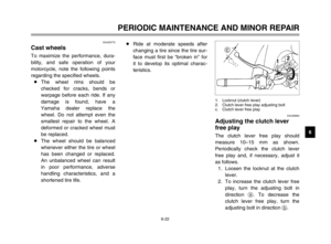 68
68 69
69 70
70 71
71 72
72 73
73 74
74 75
75 76
76 77
77 78
78 79
79 80
80 81
81 82
82 83
83 84
84 85
85 86
86 87
87 88
88 89
89 90
90 91
91 92
92 93
93 94
94 95
95 96
96 97
97 98
98 99
99 100
100 101
101 102
102 103
103 104
104 105
105 106
106 107
107 108
108 109
109
